A real-time method to measure full field retardation near quarter wavelength is proposed. The circularly polarized beam passes through a sample with a large aperture. The measuring beam then goes through a quarter-wave plate and is then split by a Wollaston prism. An image with two sub-images is then detected by a high-speed image sensor. The full field retardation near quarter wavelength can be obtained in real time by processing the image. The measured retardation is independent of the fast axis angle of the sample and the fluctuation of the initial intensity. In experiments, a wedge waveplate is measured with different fast axis angle and initial intensity, and the full field retardations are acquired. The maximum and standard deviation of the full field retardation is 1.5° and 0.4°. The validity of the method is verified.
Birefringence is the property of anisotropic optical materials, and is always characterized by the retardation and the fast axis angle. Numerous research interests have been paid to measure the retardation of birefringence samples, such as liquid crystal, biological specimens, waveplates and so on. By measuring full field retardation of a liquid crystal, the whole field thickness distribution of the liquid crystal cell is easily obtained [1]. As to the biological specimen, the retardations of the tendon and cardiac cells are analyzed to assist medical diagnosis and treatment [2,3]. Waveplate is widely used as a phase retardation device in optical communication, projection lithography and photoelectric instrumentation. The retardation error of a waveplate seriously influences the performances of the instruments and systems [4,5]. Measurement of the retardation of the birefringence sample is of great significance.
Many methods have been proposed to measure the retardation of birefringence samples. They are the phase modulation method [6,7], the intensity determination method [8,9], and the compensator-based method [10,11]. The phase modulation method employs the phase modulator to measure the retardation. But this method is pointwise measurement and needs point-by-point scanning to obtain full field retardation. The intensity determination method and the compensator-based method can measure full field retardation near quarter wavelength. But they must rotate the polarizer, the analyzer or move the compensating plate to obtain retardation of the birefringence sample. These methods are not suitable for the real time measurement of full field retardation due to point-by-point scanning of the sample, the rotation of the polarization components and the movement of the compensating plate. Real-time measurement of full field retardation is becoming increasingly important when the full field retardation of a birefringence sample is dynamically changing [12,13]. Moreover, the real time method can accelerate the measurement and make on-line measurement of the retardation possible. In this paper, a method of measuring full field retardation near quarter wavelength in real time is proposed.
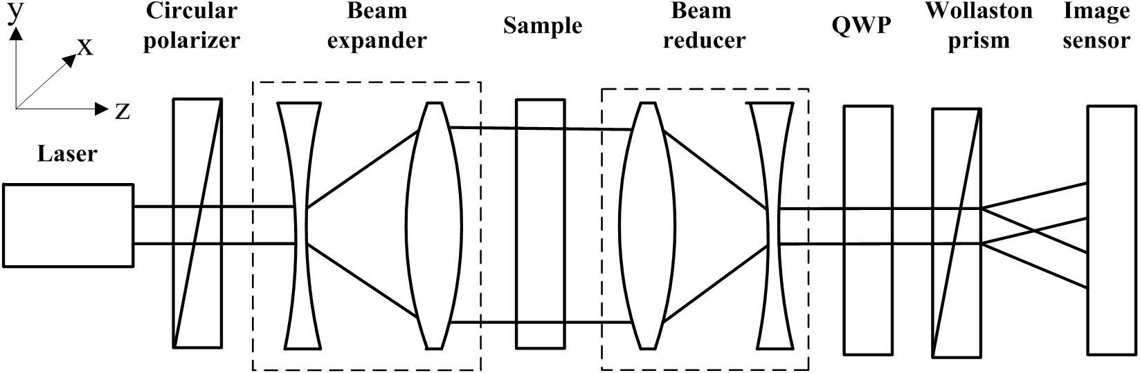
The schematic diagram to measure full field retardation near quarter wavelength is shown in Fig. 1. For convenience, the z axis of the coordinate system is chosen as the light
propagating direction and the x axis is along the horizontal direction. A collimated beam emitted from the laser passes through the circular polarizer and becomes circularly polarized light. Before and after the circularly polarized light propagating through the birefringence sample, a beam expander and a beam reducer are employed to get a large measuring aperture. The measuring beam then goes through a quarter-wave plate, and is split into two sub-beams by a Wollaston prism with small splitting angle. The fast axis angle of the quarter-wave plate is -45° relevant to the x direction. The transmission directions of the Wollaston prism are respectively along the x direction and the y direction. The two sub-beams are then detected by a high-speed image sensor. An image with two sub-images formed by the two sub-beams is then processed to get full field retardation of the birefringence sample.
The laser beam passes through the circular polarizer and becomes circularly polarized light. Its Jones vector E0 can be presented by
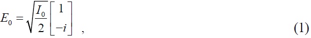
where I0 is the initial intensity. The birefringence of the beam expander and the beam reducer can be minimized to a few nanometers or less and its influence on the measurement will be very small. The birefringence of the beam expander and the beam reducer can be removed through the calibration procedure. Moreover, the birefringence can be eliminated by putting the beam expander before the circular polarizer and placing the beam reducer after the Wollaston prism. The Jones matrix of a measured pixel (x, y) of the birefringence sample is given by
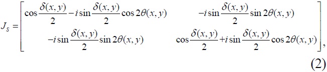
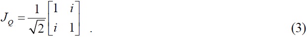
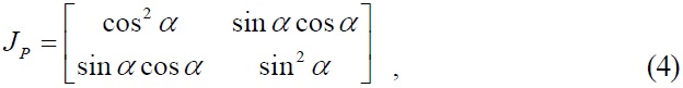
Where δ(x, y) is the retardation of the measured pixel and θ(x, y) is the fast axis angle of the measured pixel. The fast axis of the quarter-wave plate was along -45° direction, thus the Jones matrix of the quarter-wave plate is
The Wollaston prism analyzes the two sub-beams with perpendicular transmission axes. In general, the Jones matrix of the Wollaston prism can be expressed as
where
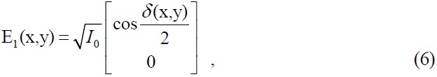
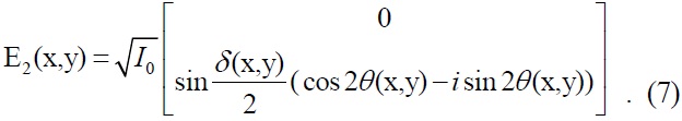
The Jones vector of a measured pixel of the two sub-imageson image sensor can be written as

When the transmission angles of the Wollaston prism are respectively 0° and 90°, the Jones vector E(x, y) in Eqs. (5) can be expressed as
The Jones vector E(x, y) is multiplied by its conjugate transposed matrix to get intensities I1 (x, y) and I2 (x, y) of each measured pixel of the two sub-images. I1 (x, y) and I2 (x, y) can be obtained by
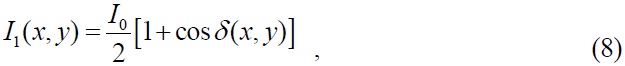
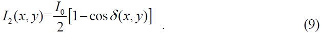
In Eqs. 8 and 9, I1(x, y) and I2(x, y) are independent of the fast axis angle of the birefringence sample. In fact, the background light intensity is also detected by the high speed image sensor. By subtracting the background light intensity in measurement, the effect of the background light can be eliminated. Thus the retardation of each pixel of the birefringence sample is obtained by
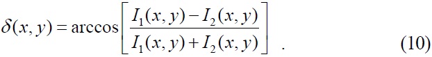
When the retardation is in the range of 45º~135º, the cosine function can be considered as a closely linear function with very small nonlinear measurement error. The full field retardation near quarter wavelength can be accurately obtained.
The two sub-images are captured simultaneously. Full field retardation of the birefringence sample can be obtained in real time through processing two sub-images. Moreover, calculation of full field retardation is independent of the fast axis angle of the birefringence sample and the fluctuation of the initial intensity.
The experimental setup is shown in Fig. 1. The light source was a He-Ne laser with the wavelength of 632.8 nm. The circular polarizer was composed of a polarizer and a quarter-wave plate. The polarizer was a Glan-Taylor prism whose extinction ratio was better than 100000:1. The quarter-wave plate was a zero order crystal quartz quarter-wave plate, whose retardation tolerance is less than λ/500. The specification of the quarter-wave plate placed before the Wollaston prism is the same as the previous quarter-wave plate. The Wollaston prism’s splitting angle was 5° and its extinction ratio was better than 100000:1. The image sensor was a CMOS camera (DH-HV2002UC) with pixel number of 1600 × 1200 and pixel size of 4.2 μm×4.2 μm. The photosensitive surface of the CMOS camera should be clear. Otherwise, the ash on the photosensitive surface will bring serious dark noise, which will reduce the spatial resolution of the retardation measurement and affect its measurement accuracy. The birefringence sample was a crystal quartz wedge waveplate. Its clear aperture was
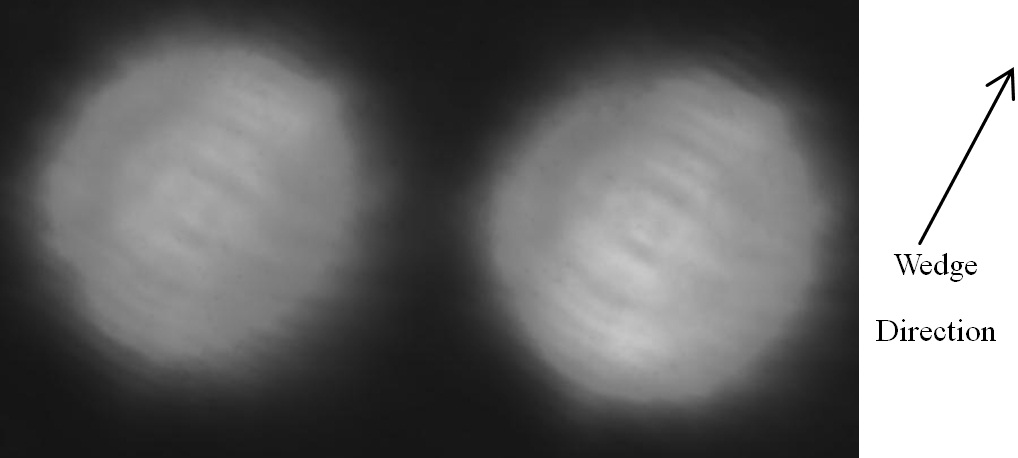
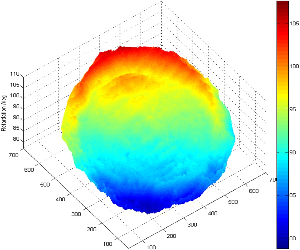
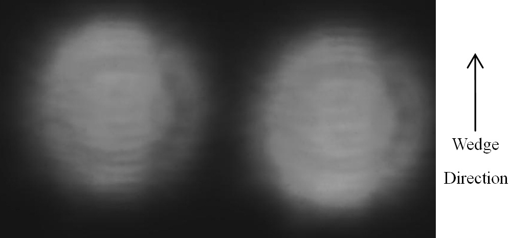
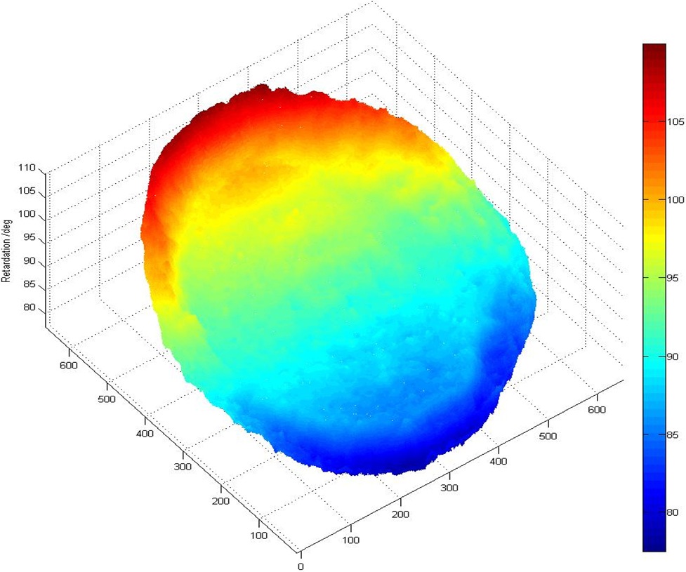
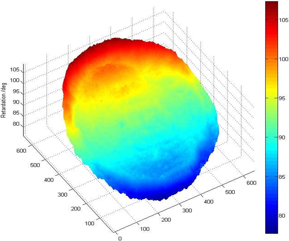
In experiments, the image of full field retardation was captured by the CMOS camera. After subtracting the background light intensity, it is shown in Fig. 2. The gray values of the two sub-images reverse value of the left sub-image decreases linearly from the top to the bottom, while the gray value of the right sub-image increases linearly. By processing the image with the program implemented in MATLAB, the full field retardation of the wedge waveplate is shown in Fig. 3. The full field retardation in Fig. 3 can be fitted into a tilted retardation plane. The maximum deviation from the tilted retardation plane is 1.5°, i.e. 2.7 nm, and the standard deviation is 0.3°. The
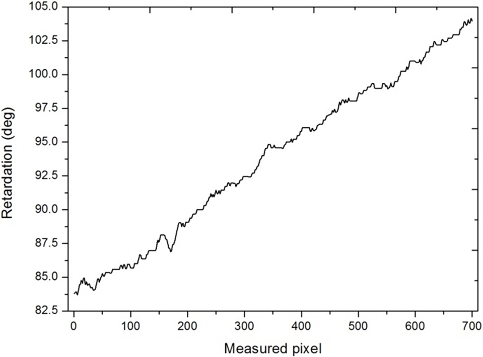
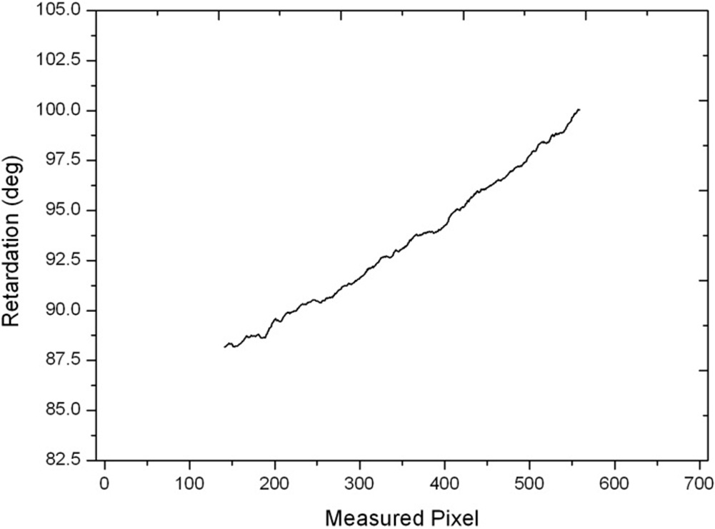
measured retardation of the middle column is displayed in Fig. 4. The retardation linearly increases from 83.9° to 103.8°, and the retardation variation is 19.9°. The measured retardation of the 600th column is shown in Fig. 5. The retardation linearly increases from 88.1° to 100.0°. The measured full field retardation is of circular shape, thus the measured pixel number in the 600th column is approximately 420, i.e. 60 % of the middle column. The measured retardation increment is 11.9°. It is approximately 60 % of the total retardation variation. The results are consistent with the nominal value and variation of the wedge waveplate.
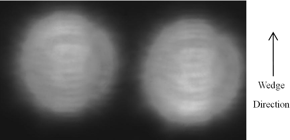
Then the wedge waveplate was rotated to change its fast axis angle. After subtracting the background light intensity, the image captured by the CMOS camera is shown in Fig. 6. By processing the image with the same program, the full field retardation is given in Fig. 7. It can be fitted into a tilted plane. The maximum and standard deviation from the tilted plane is 1.4° and 0.4°. As the wedge waveplate is rotated, the wedge direction is rotated correspondingly.
In Fig. 7, the measured retardation increased in the wedge direction and the full field retardation agrees with the result shown in Fig. 3. The full field retardation is independent of the fast axis angle of the birefringence sample.
Finally, the intensity of the He-Ne laser was attenuated to repeat the measurement under a different initial intensity. After subtracting the background light intensity, the image captured by CMOS camera is shown in Fig. 8. The full field retardation is calculated by processing the image with the same program. It is shown in Fig. 9 and can be fitted into a tilted plane. The maximum and the standard deviation of the full field retardation is 1.5° and 0.4°, respectively. The result coincides with the full field retardation shown in Fig. 3. It is verified that the full field retardation is independent of the fluctuation of the initial intensity.
In the above measurements with different fast axis angle and initial intensity, the maximum deviation and standard deviation of the full field retardation is 1.5° and 0.4°. The corresponding measuring accuracy is 2.7 nm. This specification is equivalent to that of the commercial product DIAS-1600 digital image analysis system [14], whose measuring accuracy is 2~5 nm and measuring precision is less than 1nm. The retardation measurement range of our method
is near quarterwavelength (about 80~240 nm), while the retardation measurement range of DIAS-1600 digital image analysis system is 0-280 nm. However, this product needs to rotate the polarization component to measure the retardation. Therefore, this product cannot fit for real time measurement.
A real-time method of measuring the full field retardation near quarter wavelength has been presented. The method can realize real-time measurement of full field retardation near quarter wavelength. The measurement result is independent of birefringence sample’s fast axis angle and the fluctuation of the initial intensity. In experiments, a wedge waveplate is measured with different fast axis angle and initial intensity. The maximum deviation and standard deviation of the full field retardation is 1.5° and 0.4°. The result proves the usefulness of this method.