Off-axis color shift in the dark state and gray scale inversion in an in-plane switching (IPS) liquid crystal display (LCD) device were investigated. Analyses were performed using the Poincare sphere representation. The results show that color shift in the dark state and gray scale inversion in an IPS LCD can be reduced by using a biaxial film. We confirmed the extent of these improvements by measuring the optical performance of a fabricated IPS LCD.
Thus far, liquid crystal display (LCD) devices have been employed in various applications because of their thinness, lightness, and low power consumption. With the recent increase in demand for various LCD devices such as smart phones, tablet PCs, and automotive displays, small-sized display devices are increasingly required to have high image quality. The common properties of high-end LCDs are a high pixel density, wide color gamut, wide viewing angle, and high contrast ratio. Among these properties, having a wide viewing angle is an especially important factor in automotive displays. Because the display is mounted between the driver and passenger seats, drivers view the displayed images at off-axis angles.
A strong candidate device, one that satisfies the requirements for automotive displays, is an in-plane switching (IPS) LCD [1-2]. IPS mode, the most popular mode used in mobile displays, shows wide viewing angle characteristics because the viewing angle dependence of its phase retardation is very small. Although improvements in the viewing angle characteristics of IPS mode devices have previously been achieved [3-15], solutions to the off-axis color shift in the dark state in the IPS mode are insufficient. We reported two compensation methods [16] recently, but further optimization of the compensation film is still required. Analyses on the Poincare sphere at various viewing angles were insufficient as well. Gray scale inversion in the IPS mode has not yet been considered.
In this work, we investigated the color shift in the dark state and gray scale inversion at oblique angles in the IPS mode; the analysis was performed using the Poincare sphere representation. To reduce the color shift and gray scale inversion, we used a biaxial compensation film. In addition, we confirmed the optical characteristics of IPS LCDs, based on the fabricated samples. We believe that these results will be useful to analyze and improve the viewing angle characteristics of IPS LCDs.
>
II. COLOR SHIFT AND LIGHT LEAKAGE IN THE DARK STATE
The transmittance of an liquid crystal (LC) layer between the crossed polarizers can be given as

where

where
In the crossed polarizers, whose absorption axes are 0° and 90°, the angle between the absorption axes of the polarizers is 90° at normal incidence. However, the angle between the absorption axes of the polarizers increases with an increase in the polar angle when we observe the polarizers in diagonal directions. A change in the effective angle between the two crossed polarizers results in light leakage in the dark state [6,9,12].
III. OFF-AXIS COLOR SHIFT IN THE DARK STATE AND GRAY SCALE INVERSION IN AN IPS LCD
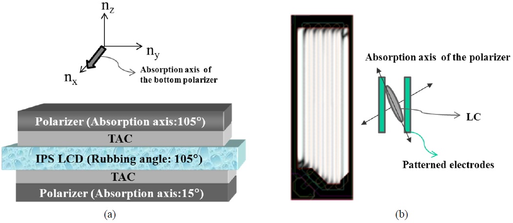
The structure of a conventional IPS LCD is shown in Fig. 1(a). Each polarizer is coated with a tri-acetate cellulose (TAC) film, which is a discotic film that protects the polarizer. Herein, the TAC (nx: 1.4793, ny: 1.47962, nz: 1.47890, thickness: 40 μm) film plays the role of a negative C plate. The rubbing angle of the IPS LCD is coincident with the
TA of the bottom polarizer. Figure 1(b) shows the electrode structure of an IPS LCD and the LC director profile on the patterned electrode. The angle between the rubbing angle and the patterned electrodes is 15°.
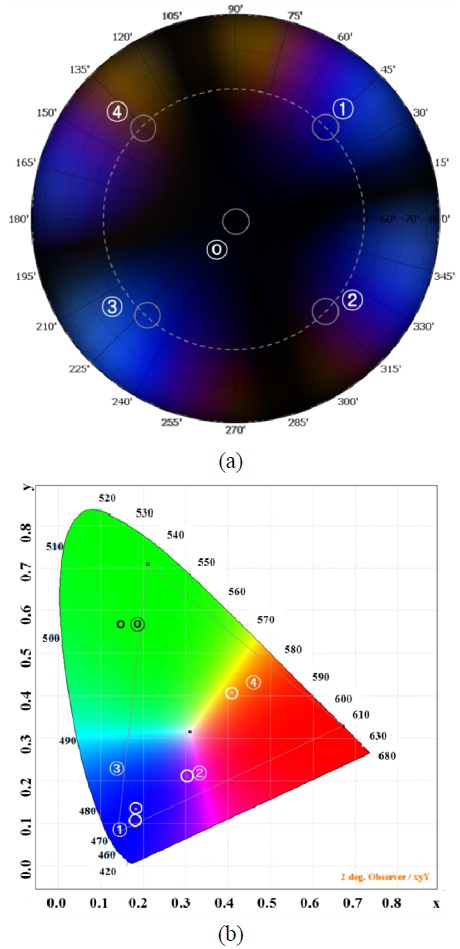
To confirm the optical properties of a conventional IPS LCD, we performed a numerical calculation using commercial software, TechWiz LCD 1D (Sanayi System Co., Ltd, Korea). The parameters used in the numerical calculation are as follows. The extraordinary and ordinary indices of the LCs are 1.554 and 1.467, respectively. The thickness of the LC layer is 3.4 μm. The surface pretilt angle is 2°. Figure 2 shows the color characteristics of an IPS LCD in the dark state with the structure shown in Fig. 1(a). Color contour represents viewing-angle-dependent color on the color coordinate CIE1931. At normal incidence (ⓞ), a perfect black color in the dark state is shown in the color contour. The bluish (①, ③) and yellowish (④) colors are observed in diagonal directions. An asymmetric color contour can be observed as shown in Fig. 2(a), because the LC layer has a nonzero surface pretilt angle. Colors, which are indicated on the color contour, spread out on CIE 1931, as shown in Fig. 2(b).
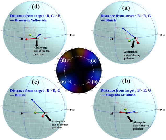
Color shift in the dark state along the viewing angle comes from wavelength dispersion by the homogeneously-aligned LC layer and TAC films between crossed polarizers. By depicting polarization states at each wavelength on the Poincare sphere [17], as shown in Fig. 3, the detailed causes of color shift in the dark state can be analyzed. The polar angle is 50°. The azimuthal angles of the viewing points are 45°, 135°, 225°, and 315°, respectively. The presented points represent the polarizations of red, green, and blue light passed through an IPS LCD with the structure shown in Fig. 1(a). The amount of the light leakage can be estimated approximately by the difference of the distance between the point at each wavelength and the target point that corresponds to the absorption axis of the top polarizer. The distance from the target point to the blue point is longer than the distance from the red or green point to the target point, as shown in Figs. 3(a), (b), and (c), such that a bluish color is observed in the color contour, exhibiting blue shift in the dark state. In the case of Fig. 3(d), the shorter distance from the blue point to the target point than the red or green point
causes a yellowish or reddish color, exhibiting red shift in the dark state. Moreover, the pretilt angle causes a different
level of retardation, in which there is both a color and polarization difference between Figs. 3(c) and (d).
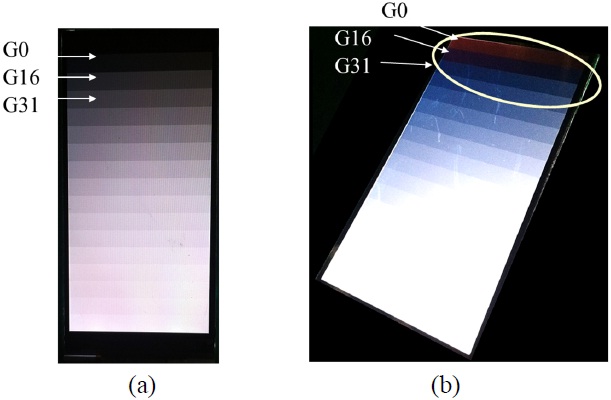
Because gray scale inversion must be prevented if one is to have good viewing angle characteristics (regardless of the LCD mode), we consider gray scale inversion in the IPS mode. Figure 4 shows an example of gray scale inversion phenomena in a fabricated IPS LCD panel using structure of Fig. 1(a); in this case, gray scale bars from gray level G0 to gray level G255 are shown. At normal incidence, the scales are changed gradually from the top to the bottom of the panel, as shown in Fig. 4(a); there is gray scale inversion at a polar angle of 50° and an azimuthal angle of 150°, as shown in Fig. 4(b).
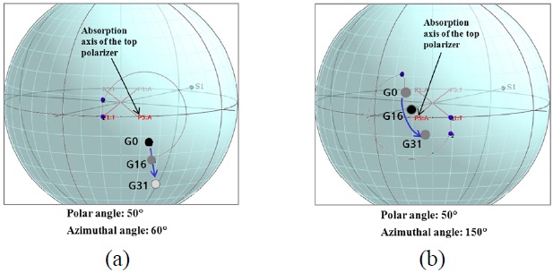
To confirm the detailed causes of the gray scale inversion problem, we analyze the polarization states at each gray level on the Poincare sphere, as shown in Fig. 5. Polarization states are depicted at two viewing angles. Figure 5(a) shows the polarization state when the polar and azimuthal angles are 50° and 60°, respectively. The distance from the target point, corresponding to the absorption axis of the top polarizer, to each gray level point increases when the gray level increases. Figure 5(b) shows the polarization state when polar and azimuthal angles are 50° and 150°, respectively. Compared to the distance from each gray level point to the target point; in particular, the gray level point of G16 is significantly closer to the target point than G0, resulting in the gray scale inversion phenomenon.
IV. IMPROVEMENT OF OFF-AXIS COLOR SHIFT AND GRAY SCALE INVERSION IN AN IPS LCD
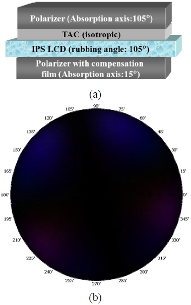
To reduce the color shift in the dark state and gray scale inversion at certain viewing angles, we employ a polarizer coupled with a biaxial film (nx: 1.521, ny: 1.519, nz: 1.52, thickness: 138 mm). The compensated IPS LCD structure is shown in Fig. 6(a). As indicated by the color contour in Fig. 6(b), there is little color shift over the entire range of viewing angles in the dark state relative to a conventional IPS LCD, shown in Fig. 2(a).
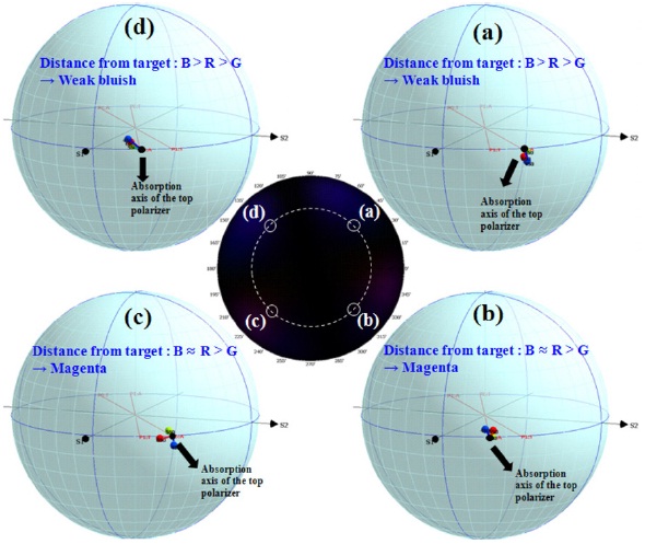
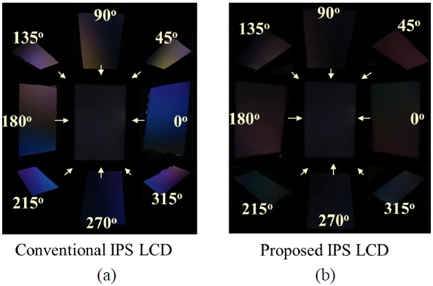
To analyze the improvement in the color shift in the dark state, we confirm the location of the polarization state at red, green, and blue wavelengths after passing through the proposed IPS LCD on the Poincare sphere, as shown in Fig. 7. Although a weak bluish color is seen in Figs. 7(a) and (d), the distances between each light and the absorption axis of the top polarizer on the Poincare sphere are much shorter than those of the conventional IPS LCD shown in Fig. 5. Thus, we can reduce the color shift in the dark state over the entire range of viewing angles using a biaxial compensation film. Figure 8 shows the dependence of color characteristics on the viewing angle in the dark state in the fabricated IPS LCD compared to the conventional IPS LCD. At a fixed polar angle of 50°, the color shift is improved at almost all azimuthal viewing angles.
In addition, we verified whether there was any gray scale inversion problem in the compensated IPS LCD at a fixed
polar angle of 50°. Differently from the conventional IPS
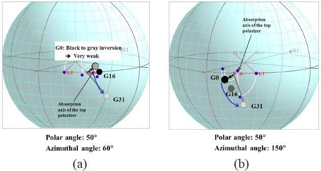
LCD (see Fig. 5(a)), the compensated IPS LCD exhibits gray scale inversion at an azimuthal angle of 60° (see Fig. 9(a)). However, the gray scale inversion between a gray level of G0 and a gray level of G16 is very weak. Moreover, significant gray scale inversion can be observed in the conventional IPS LCD at an azimuthal angle of 150° (see Fig. 5(b), whereas, at the same angle, there is no gray scale inversion in the compensated IPS LCD (see Fig. 9(b)).
We studied the optical characteristics of an IPS LCD. The retardation of the TAC film and the LC layer at off-axis causes a color shift in the dark state and the gray scale inversion problem. A detailed analysis has been carried out by confirming the location of polarization states at each wavelength on the Poincare sphere. Furthermore, we have shown that we can reduce the effects of color shift in the dark state and gray scale inversion using a biaxial compensation film. We believe that the proposed method can be very useful for optical analysis of various emerging IPS LCDs.