In this paper, we identify an intractable problem known as light leakage, which is more critical in IPS mode compared to VA mode, and we propose diverse ways of tackling this issue. In general, the light leakage phenomenon arises from the stress generated by the bending of the LCD panel. This paper proposes three processing methods for reducing the mechanical stress causing LCD panel bending and light leakage. Changes in the lamination process of polarizer films and the application of a buffer layer can reduce the bending level by 32% and 21%, respectively. The combination of polarizer films according to variation of thickness also help to reduce the panel bending. In particular, it is important that a combination of these proposed modifications could provide the better solution to reduce the panel bending. From a geometric solution to a change in materials, the whole history of IPS light leakage solutions is presented succinctly. With this paper―or review, to be more precise―the mechanism underlying the light leakage phenomenon is understood, and this understanding is applied to derive answers to the problem caused by the phenomenon in question.
In this day and age, LCDs are by far the most widely used display devices owing to their attractive properties such as wide viewing-angle, high contrast ratio, low response time, and minimal color shift [1,2]. Two main types of liquid crystal (LC) alignment are commonly used in LCDs. One is vertical alignment (VA), which was introduced as multi-domain vertical alignment (MVA) [3], while patterned vertical alignment is an enhanced version of conventional VA in terms of response time [4]. The other type is the homogeneously aligned LC, the so-called in-plane switching, or IPS for short [5]. In particular, the IPS LCD is known for its high image quality with a wide viewing-angle, which is attributed to the switching of LC directors on a plane via the application of a transverse electric field [6,7]. In the case of VA mode, its vertically aligned liquid crystals give it more space to move about without affecting the overall retardation. Thus it is less sensitive to external stress and optical distortion. However, the IPS LCD, unlike the VA type, is more vulnerable to the light leakage problem. Its in-plane aligned LC can have its direction changed significantly by an external impact, due to which the transmittance increases when the LC is twisted off-axis in relation to the crossed polarizers. The transmittance in IPS mode can be expressed as follows.

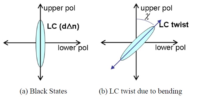
where the retardation, dΔn, and the azimuth angle, χ illustrated in Fig. 1 are the factors directly affecting the transmittance [8]. In general, for IPS LCDs the retardation, dΔn is not dependent on the voltage supplied, but on changes in the azimuth angle, χ, that may be due to a myriad of factors. In short, light leakage occurs when χ ≠0. Thus, it is essential to find a way to keep χ = 0 [9].
When the LC cell is sandwiched between two crossed linear polarizers in LCDs, light leaks at an oblique angle. This can be the result of several factors, such as off-axis light leakage from the crossed polarizers, optical anisotropy of the LC layer, and light scattering from the LC layer; the effects of these factors can be alleviated by compensating for the off-axis light leakage [2,10-12].
However, in IPS-LCDs, the light leakage phenomenon arises from the stress generated due to bending of the LCD panels; contact between the case top and the LC panel causes distortion of the liquid crystals inside the panel. This bending accelerates considerably, especially during reliability testing or high-temperature processing. Because ambient heat releases water molecules from polyvinyl alcohol (PVA), the resilience of the stretched PVA in a polarizer causes the bending as the stretched PVA polarizer film tries to shrink back to its original size, exerting a contractile force. Moreover, unbalanced shrinkage of the upper and lower polarizer films,
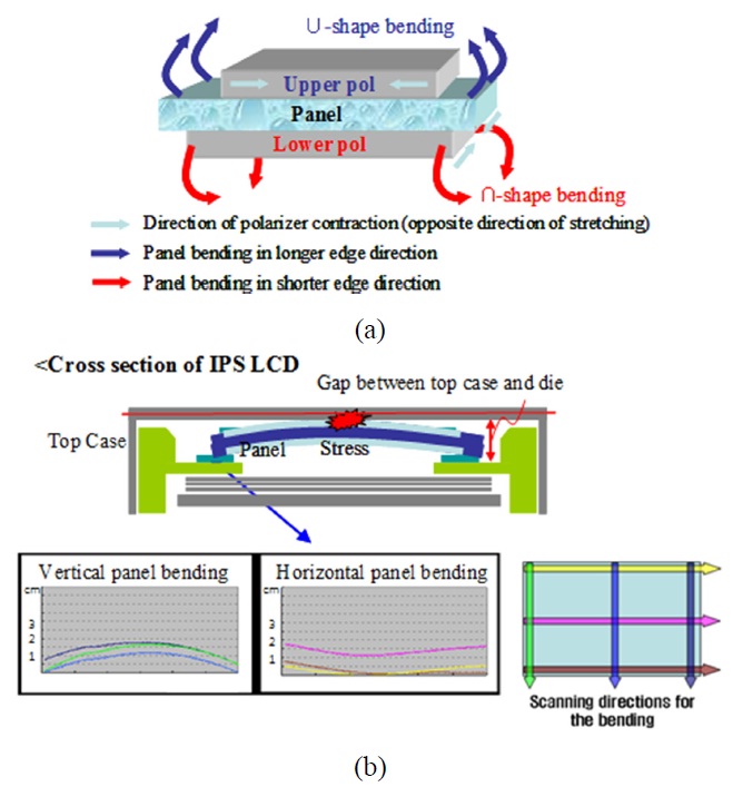
due to the difference between stretching direction and composition, leads the panels to bend even more. As shown in Fig. 2(a), panel bending occurs along both the longer edge and the shorter edge, according to the stretching direction of the polarizers. The upper polarizer is responsible for U-shaped bending along the longer edge, while the lower polarizer causes ∩-shaped bending in the shorter edge. When the bending deviation of a panel is greater than the gap allowed between the panel frame and the panel itself, which is approximately 2 mm, there is contact resulting in stress, as shown in Fig. 2(b). Consequently, the liquid crystals are twisted off their axis, producing light leakage [13].
We need to take into account both the initial bending and the bending after reliability testing, because the latter is considered as an actual problem; generally, initial bending is not great enough to cause serious light leakage. Therefore, it is important that we observe and improve the light leakage in both cases. In this paper, we review a variety of techniques for preventing light leakage in IPS LCDs using diverse modifications. First, we focus on the lamination process; we then analyze possible modifications that can be made, such as utilizing supportive films, altering the thickness of the polarizers, and changing materials.
II. EXPERIMENTATION AND ANALYSIS
In this paper, we propose three main approaches: changes in the lamination process of polarizer films; the application of a buffer layer; and the combination of polarizer films according to variation of thickness. This section provides detailed descriptions of each technique. To enable an unbiased analysis of the results, a 42-inch LCD TV (model code: LC420WUN) was used for all the tests.
2.1. Changes in Lamination Process of Polarizer Films
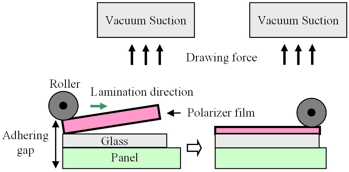
Figure 3 shows the process in which the polarizer film is laminated to the glass. First, a stretched polarizer film is placed on the glass. The vacuum suction stage is located in an inverted position on the top of the lamination machine, holding the polarizer film. In order to laminate the polarizer, the vacuum stage tilts to one side so that the edge of the polarizer can stick to the glass. As the roller rolls in, the
polarizer is pressed down onto the panel glass, completing the lamination process.
2.1.1. Modification of Roller Gap for Reduction of Residual Strain
For the control of panel bending, the lamination method described above is crucial. By imagining a polarizer film as a thick piece of pizza dough, we can appreciate the relationship between the force exerted on the film during the lamination stage and its tendency to shrink back to its original shape. The less force applied to the film, the smaller the area of film that will make contact; hence, there will be less bending of the panel. First, we increase the gap between the roller and the stage to reduce the pressure applied. This will reduce the residual strain in the polarizer film and will help to alleviate the bending of the panel. In our experiment, after changing the roller gap from 14.0 mm to 14.1 mm, we measured the initial bending and the bending after the reliability test. For the accurate measurement of the initial panel bending, a laser-based 3D measuring machine, the PFB Coordinate Measuring Machine (Duckin®) was used [14]. For the analysis of the panel bending after the reliability test, which is performed in a chamber at 60℃ for 72 hours with backlight turned on, the light leakage level previously set according to its severity was used. The tests were carried out using a V4 S&N model (LC420WUD-SBT1) with a Sumitomo polarizer.
2.1.2. Modification of Vacuum Suction Power for Reduction of Residual Strain
In this case, we adjusted the suction power of the vacuum in the upper stage, which holds the polarizer, in order to decrease the stretching force in the polarizer film during the lamination process. As shown in Fig. 3, the vacuum suction is used to hold up the polarizer film. The suction power determines the degree of stretching in the polarizer when the roller is introduced. Reducing the suction will relieve the strain on the polarizer during the lamination process. We reduced the power ofm suction to a
minimum, i.e., from 20 kPa to 5 kPa, in order to observe the effect more clearly. The same methodology mentioned above in 2.1.1 was used for the analysis of the bending.
2.1.3. Alternation of Lamination Direction
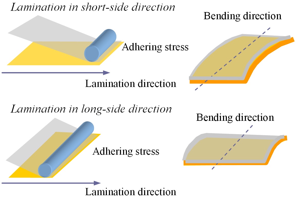
The other important factor that affects the shrinkage of the polarizer film is the lamination direction. The direction of panel bending depends on both the stretching direction of the PVA and the direction of the lamination. We project that the direction of the roller will cause ∩-type bending parallel to the lamination direction, as shown in Fig. 4. This hypothesis is based on the idea that the stress imposed by the roller along its direction of movement will stretch the film in the same direction, leading to greater shrinkage. Conventionally, all polarizer film has been laminated along the longer side of the panel, but in this experiment, we propose lamination along the short side, perpendicular to the direction of stretching of PVA, in an attempt to reduce the panel bending.
2.1.4. Pre-aging Process
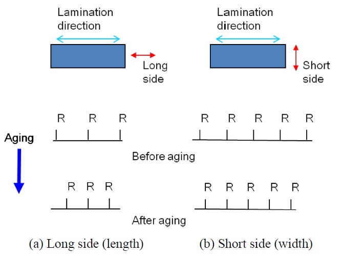
Films like PVA, which is an atactic polymer, TAC (triacetyl cellulose), and PMMA (poly methyl methacrylate), which is a thermoplastic material, have a high thermal expansion coefficient, α. Atatic polymer has group R randomly aligned so it is easily stretched. To overcome this drawback, we conducted the following aging process before laminating the polarizer film on the glass. First, the polarizer film underwent a high temperature aging process (in this case we propose 40℃ for 12 hours) to expand the molecules in the polarizer films. Then, the film was applied at room temperature in order to relax the film via contraction as shown in Fig. 5. Consequently, as Fig. 5 shows high temperature aging stretches and then room temperature shrinks the film which leads to better and tighter alignment in both long and short sides. Above all, as in Fig. 5(a) molecules along the film stretch direction have high mobility, compared
to ones along the perpendicular to the film stretch direction, leading to stronger stretch. Accordingly, this reduces panel bending by laminating film that is already contracted.
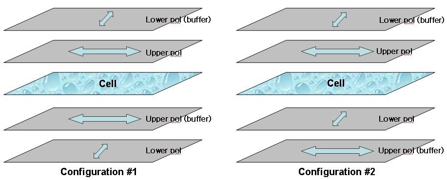
In this section, we propose the use of buffer layers, stretched PVA films with no iodine accretion, in order to counterbalance the bending caused by polarizer shrinkage. The basic principle of the experiment was to verify the effectiveness of buffer layers and to find their optimal configuration, as shown in Fig. 6.
The two configurations were prepared and tested, together with a normal sample, to which no buffer layer was applied, that served as a reference. All three samples were measured before and after a high-temperature reliability test (72 hours at 60℃). Measurements were made using a 3D measuring machine, the PFB Coordinate Measuring Machine (Duckin®) [14].
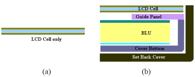
In this experiment, we also did additional tests. We applied the bezel-free module, allowing the buffer layers to be applied easily with no thickness restriction, as shown in Fig. 7; this bezel-free structure is not only what future LCDs will look like, but also eliminates the limitations on film thickness.
2.3. Miscellaneous Modification of Polarizer Film
In this section, we focus on the polarizer itself, which is responsible for the lion’s share of the light leakage. We adjusted its thickness, material composition, and adhesives in order to determine the correlation between the polarizer film and the light leakage.
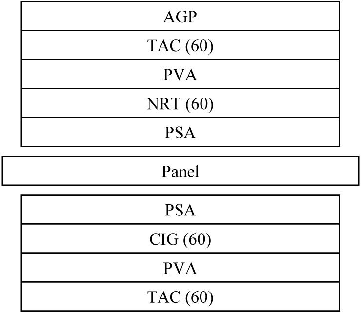
The IPS LCD used in our study contains an upper and a lower polarizer film, and a liquid crystal (LC) layer that is sandwiched between these two crossed polarizer films. Figure 8 shows the conventional structure of the IPS LCD panel, which is used for reference in this section. Each
polarizer film consists of stretched PVA. Cellulose triacetate (TAC) films are generic protective films that always sit on the top and the bottom of the PVA. The PVA layer is sandwiched between a pair of TAC films, referred to as the outer and inner TAC. The inner TAC can be replaced by other acrylic films, such as CIG from Nitto corp. or ACE from LG Chemical, both of which are acrylic- rather than cellulose-based. The thicknesses of the films in micrometers are shown in parentheses. The polarizer films are attached to the panel with pressure sensitive adhesive (PSA).
We conducted split tests under different conditions to investigate the various effects of each layer on the light leakage phenomenon. We applied different protective films, such as inner TAC, CIG, and ACE, and observed the effects by measuring the bending in two different modes, AH-IPS and UH-IPS. In addition, we changed the thickness of the PVA and protective films and tested different PSAs.
2.3.1. Thickness of Polarizer Film
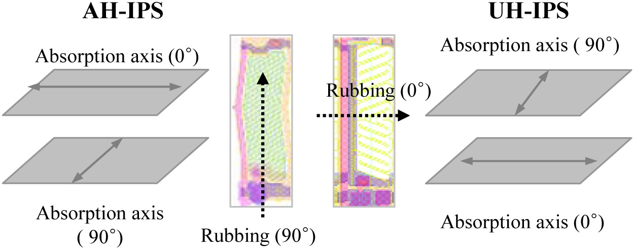
First, we examined the effect on the panel bending of a change in thickness of the polarizer films. We prepared two different types of IPS LCD, AH-IPS and UH-IPS. The two modes had different rubbing directions; therefore, we expect different results as shown in Fig. 9.
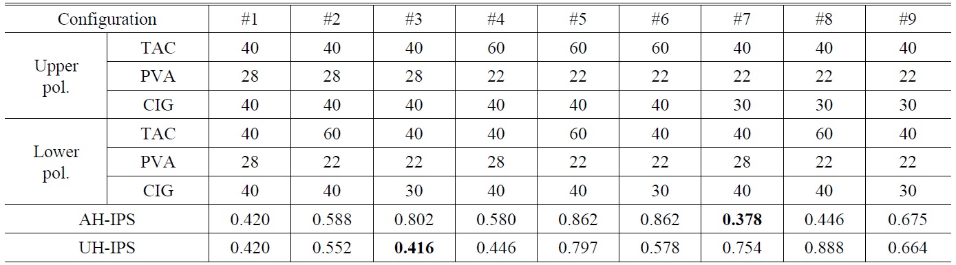
Three different configurations of polarizer films were tested, each possessing TAC, PVA, and CIG layers of different thicknesses. The combinations are shown in Table 1.
[TABLE 1.] Test conditions for polarizer films and experimental results of AH-IPS and UH-IPS LCDs

Test conditions for polarizer films and experimental results of AH-IPS and UH-IPS LCDs
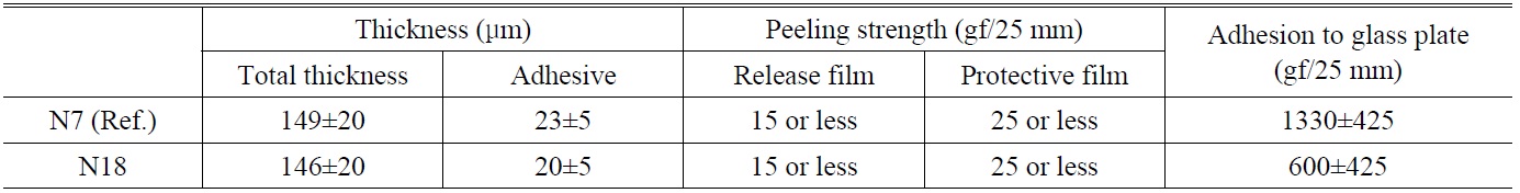
[TABLE 2.] Adhesives, N7 and N8, used in tests

Adhesives, N7 and N8, used in tests
2.3.2. Permeability of Polarizer Film
The polarizer is a hygroscopic material and, of the materials used, PVA contains the most moisture due to its wet manufacture process. During the reliability test, the high temperature drives the moisture out of the polarizer, causing the PVA to shrink back to its original size. It is thus vital to control the permeability of the PVA to make sure the moisture is either drained or hermetically confined. In the latter case, it is desirable to use a less permeable material to prevent water molecules seeping out of the PVA under high temperature conditions and causing panel bending.
2.3.3. Modification of Adhesive to Change Adhesion
We changed the PSA for the polarizer film on the assumption that the adhesion of the PSA has a slight influence on the panel bending. We used two different PSAs for the polarizer film: N7 and N18. The detailed features of these two adhesives are given in Table 2. Then, we investigated the effect of the adhesive on the penal bending. We applied PSA to one of the upper or lower polarizer films, or to both upper and lower polarizer films, to clarify the effect on the panel bending.
3.1. Modification of Lamination Technique
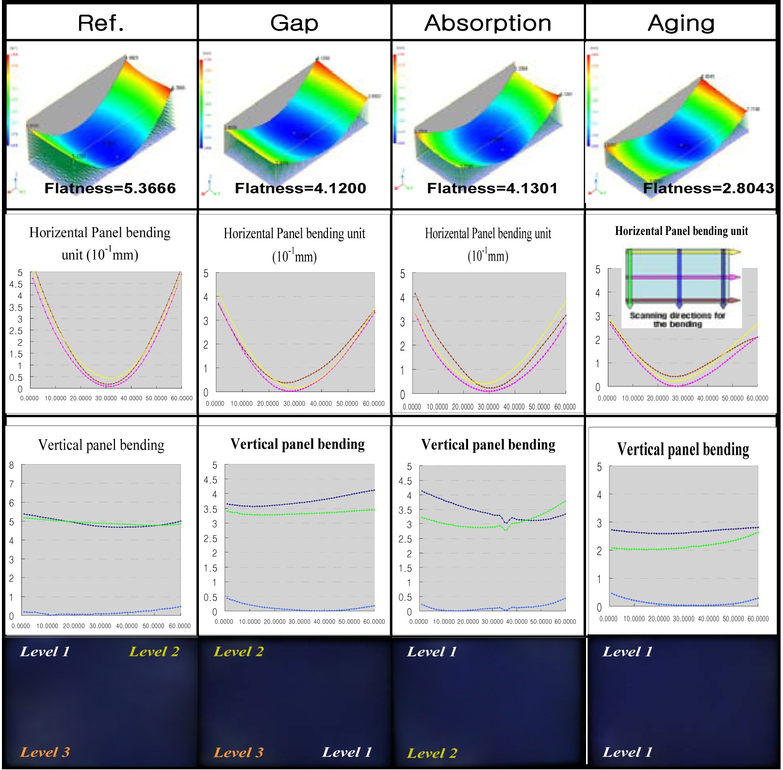
In this section, we present the experimental results from the proposed modifications to the lamination process. The experimental results when we adjusted the lamination gap, adsorption rate, and lamination after aging are shown in Fig. 10.
The first column in Fig. 10 represents the bending profile?the vertical bending along the short edge and horizontal bending along the long edge?and FOS (front of screen) image for the reference polarizer film. The second, third, and fourth columns the results of changing adhering gap, absorption rate, and lamination after aging, respectively. Although the second and third columns show an improvement in panel bending, it is not sufficient to prevent the light leakage phenomenon. However, lamination after hightemperature aging (40℃, 12hr) is different. The flatness of reference polarizer film is 5.3666. However, the flatness of polarizer film after the aging process is improved to 2.8043. As the FOS images in the last row show, this technique is remarkably effective in preventing light leakage. We can therefore conclude that lamination after high-temperature aging of polarizer film is effective in reducing bending levels sufficiently to prevent the light leakage phenomenon.
3.2. Modification of Lamination Direction
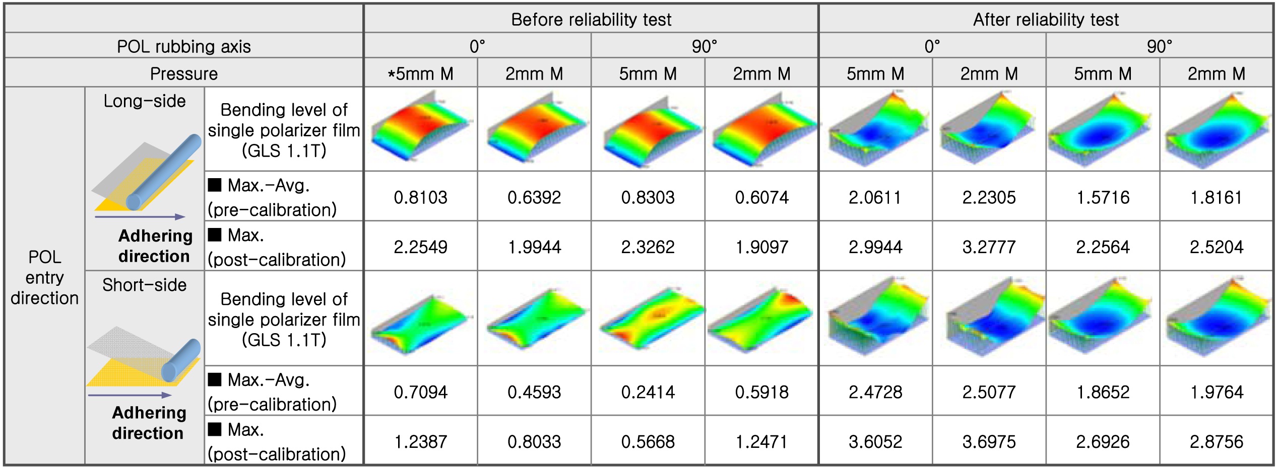
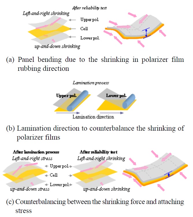
The bending profiles along different lamination directions are shown in Fig. 11. Prior to the reliability test, ∩-type bending perpendicular to the lamination direction was caused by the stress of lamination. After the reliability test, only a small degree of panel bending was observed when the adhesion process was started along the long side, rather than along the short side. In addition, a better result was obtained when the adhering direction of the polarizer film was perpendicular to the rubbing direction by achieving counterbalancing between the shrinking force and attaching stress as shown in Fig. 12(c). Consequently, the optimum approach to the adhesion of polarizer films is to attach the upper polarizer film to the long side, while the lower polarizer film should be attached to the short side. Thus, the bending of the panel will be improved if the lamination
direction is perpendicular to the original shrinking direction of the polarizer film, which is equivalent to the rubbing direction.
The panel bending after the reliability test is caused by the shrinking force in the rubbing direction, as shown in Fig. 12(a). Then, we laminate the polarizer film, which causes the lamination stress in a direction opposite to the rubbing direction during the lamination process, as shown in Fig. 12(b). This stress can compensate for the shrinking due to the rubbing process. The upper polarizer film is attached to the long side, to compensate for the right-and-left shrinking force due to the rubbing direction, while the lower polarizer film is attached in short side direction to compensate for the up-and-down shrinking force, as shown in Fig. 12(c).
3.3. Modification of Polarizer Films
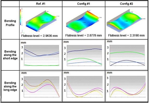
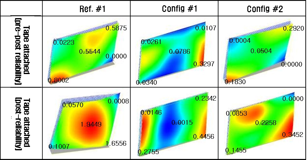
First, we give the experimental results from the application of a buffer layer to alleviate the stress from the stretched polyvinyl alcohol (PVA) films on the glass substrate. We prepared one reference and two proposed configurations, which are shown in Fig. 6.
Prior to the reliability test, the configuration #1 sample
showed flatness comparable to that of the reference sample, while configuration #2 decreased bending by 21.2%, as shown in Fig. 13. This means that buffer layer-applied panels, like the typical reference sample, do not generate light leakage in the initial state.
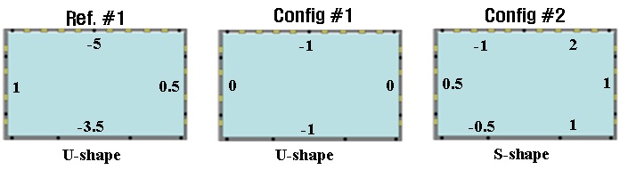
Measurements after the reliability test conditions, as shown in Fig. 14, indicated a reduction in the bending levels for both configurations, each configuration having a different bending shape due to differences in the stress relaxation mechanism. Furthermore, configuration #1 showed a greater decrease in the bending level after the reliability test than did configuration #2. The numbers in mm given in Fig. 14 were obtained from manual measurements using a ruler and a surface plate, and represent the bending levels of each sample in the LCD-cell-only structure.
As Fig. 14 shows, the bending levels overall are significantly reduced by the application of buffer layers in a bezel-free structure. While both configurations #1 and #2 show a lesser degree of bending than does the reference sample, configuration #1 is slightly flatter than configuration #2. Furthermore, both configurations #1 and #2 generate no light leakage, in contrast to the reference sample.
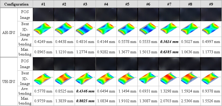
Next, we show the experimental results from changing the thickness of the polarizer films. We set three different conditions for the upper and lower polarizer films, resulting in nine cases, as shown in Table 2. In this experiment, the degree of bending was minimized when the upper and lower polarizer films were sufficiently thin and asymmetric. As shown in Table 2, the minimum average bending for UH-IPS and AH-IPS was obtained from case 3 and case 7, respectively. Consequently, the optimum condition for an AH-IPS is when the thickness of the upper polarizer film is less than that of the lower polarizer film, whereas for a UH-IPS the best result is obtained when the opposite relation applies.
From the simulation result for AH-IPS in Table 2, the panel bending that is related to the thickness of the upper and lower polarizer films has the following features. When the thickness of the upper polarizer film and that of the lower one are equal, the left-and-right stress in the upper polarizer film is greater than the up-and-down stress in the lower film. This will cause significant panel bending. As the thickness of the upper polarizer film increases, the
panel bending of the AH-IPS becomes worse. Decreasing the thickness of the upper polarizer film reduces the leftand- right stress until it counterbalances the up-and-down stress in the lower polarizer film, thus alleviating the panel bending in the AH-IPS panel. Similarly, UH-IPS panel bending can be improved, based on a similar argument. In the UH-IPS, the relation is the inverse of the AH-IPS panel. Thus, to reduce the magnitude of panel bending in UH-IPS, the upper polarizer film should be thicker than the lower film.
Figure 16 shows both the FOS image and 3D images of the measurements of average and maximum panel bending for AH-IPS and UH-IPS modes. As shown in Table 2, there are nine configurations, each with its own different thickness of TAC, PVA, and CIG layers for the upper and lower polarizer films. Measurements after the reliability test show a reduction in the panel bending for both AH-IPS and UH-IPS modes when the TAC is thin. However, the AH-IPS panel showed a greater decrease in both bending and light leakage level when the thickness of the upper layer was less than that of the lower layer. The reverse was true for the UH-IPS panel, which showed the best results when the lower layer was thinner than the upper layer.
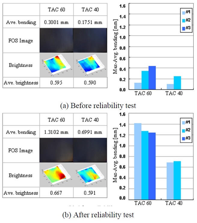
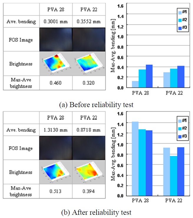
We then analyzed the effect of the thickness of the PVA layer on the panel bending. We prepared two polarizer films that had different thickness of PVA: 28 μm and 22 μm. As shown in Fig. 17, there was little difference between the two configurations before the reliability test. However, after the reliability test the panel containing 22 μm PVA had 34% less bending than the 28 μm PVA and was 23% better in terms of max-average brightness. It appears that the thinner the PVA, the less the panel bending. In particular, the effect of reduced PVA thickness on the panel bending is significantly greater when the thickness of TAC is fixed
We also analyzed the effect of the thickness of the outer TAC layer on the panel bending. As shown in Fig. 18, there was little difference between the two configurations with different thickness of outer TAC. After the reliability test (60℃, 120 hours), the panel bending was significantly less for the panel containing an outer TAC layer with a thickness of 40 μm rather than 60 μm. The experimental results showed 46.7% less panel bending, as well as 25.7% better max-average brightness for the thinner TAC layer.
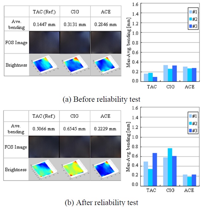
Figure 19 shows the experimental results using the combination of lower polarizer films. The reference panel contained TAC with a thickness of 60 μm, and two variations where the TAC in the lower polarizer film was replaced by CIG with a thickness of 40 μm, and ACE with a thickness of 50 μm. The average panel bending for the reference panel
containing TAC was 50 μm after the reliability test. When the polarizer film contained an ACE layer in place of the TAC layer, the average panel bending was 56% less. Since ACE has the greatest up-and-down stress compared with the other materials, this stress is big enough to counterbalance the left-and-right stress in the upper polarizer film. The panel
bending was also significantly less when the inner TAC was replaced by CIG. The experimental results after the reliability test for polarizer film containing a CIG layer showed a 56.0% lower degree of panel bending, compared to the reference panel that had TAC in both upper and lower polarizer films.
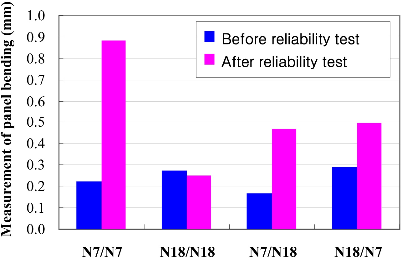
Finally, we examined the effect of the adhesive on the panel bending. Figure 20 shows the experimental results for four cases. The magnitudes of panel bending before reliability test were similar in all cases, while the results after reliability test were significantly different. When a weaker adhesive was used for both upper and lower polarizer films, the panel bending was 71% less. In addition, the panel bending was improved by 43% and 46% when this change was applied only to the upper polarizer film or to the lower one, respectively. Consequently, it is clear that a PSA with weak adhesion can reduce the magnitude of panel bending and can help prevent the light leakage phenomenon.
We investigated every possible means of reducing the light leakage phenomenon. An understanding of the exact mechanism of the problem facilitated an approach to the solution. This paper presents three major processing methods to reduce the mechanical stress causing LCD panel bending and light leakage. First, the lamination after high-temperature aging of polarizer film significantly reduces the panel bending almost by half compared to the reference panel. Second, the modification of lamination direction is to counterbalance shrinking force and lamination stress of the polarizer film. After reliability testing, the bending level is reduced by 32%. Finally, we give the experimental results for the modification of polarizer films. The application of a buffer layer can decrease panel bending by 21.2%. In addition, the degree of bending is reduced when the upper and lower polarizer films are sufficiently thin and asymmetric. We also provide the simulation results for changing the thickness of the PVA and outer TAC layers on the panel bending. We prove that a combination of these modifications could lead to a breakthrough in this critical issue. The display industry, by its very nature, is inevitably prone to such bottlenecks and this paper will be a milestone for those who endeavor to develop display products. Continuing efforts are the only solution to this problem and research engineers are continuing to make great efforts in this regard.