In order to get near infrared (NIR) information in remote sensing, the material of the telescope is very important. The refractive materials are limited in the application because of dimensions in the high resolution telescope. The reflective telescope can avoid the material difficulties and give high optical efficiency without absorbing. The normal reflective telescopes with an intermediate image just provide a small field of view (FOV), just as Gregorian telescope [1] and three mirror anastigmatic (TMA) telescopes do [2,3]. The former one can give a compact configuration but only a few arc minutes FOV, the latter one can give more than 5°FOV but large configuration and when the FOV is wider than 10°, the difficulty of manufacture will increase greatly since the speed for some mirrors will become very fast [4]. The TMA telescope or the four-mirror-anastigmatic telescope without an intermediate image can show more than 10°and have a compact configuration [2,5], but the stray light will influence the image quality especially for the LWIR (long wave infrared) spectral range such as the wave length longer than 10 μm. This range is caused by the telescope materials when the environmental temperature is higher than 300 K [6]. A (cold) field stop near the intermediate image can restrain lots of LWIR stray light.
In most of the TMA telescopes with an intermediate image, the exit pupil will be in front of the focal plane with a longer distance [2]. So that the Lyot stop [7-9] cannot be located there since the cold chamber is usually short. In the NIR telescope, there is no NIR irradiance from the telescope materials and the cold chamber is not needed; the Lyot stop will not be used since most of the NIR stray light will be restrained by the entrance pupil, the field stop, the narrow-band pass filter and the baffle of the telescope.
In order to observe the NIR spectral targets, a wide strip FOV five-mirror-anastigmatic telescope was designed with four powered mirrors and without obscuration in the optical path. There is an intermediate image in the optical system and a stop is located in front of the focal plane, but it is not a Lyot stop. The stop in front of the focal plane and the finite dimension of the fifth mirror (and the third mirror) can restrict the angle from the pixel to the fifth mirror (and the third mirror). The strip full FOV is 20°×0.2°, the entrance pupil diameter is 100 mm, and the effective focal length is 250 mm. The diameter for the Airy Disk is about 10.48 μm with wave length of 1.75 μm. The image quality of the five-mirror-anastigmatic telescope is near the diffraction limit, and the pixel pitch is 15 μm.
II. OPTICAL DESIGN OF AN OFF-AXIS FIVE-MIRROR-ANASTIGMATIC TELESCOPE
2.1. Optical Design Requirements
If there is an obscuration in the diffraction limited optical path, the optical MTF (Modulate Transfer Function) will be decreased again especially for the longer wavelength. In order to keep higher MTF, the obscuration should be removed from the optical path. Therefore, the telescope configuration should be chosen as an off-axis mirror telescope.
In the IR optical system, the stray light should be restrained in order to improve the image quality. Or else there will be some fog as the back-ground to decrease the image quality. In order to restrain the stray light, there should be an intermediate image in the optical system where we can locate a field stop. With the help of a field stop near the intermediate image, a stop in front of the focal plane, the narrow-band pass filter for the detector and the baffle in front of the third mirror, most of the NIR stray light will be restrained.
The strip full FOV is 20°×0.2°, the entrance pupil diameter is 100 mm, and the effective focal length is 250 mm. The spectral range is 0.85 -1.75 μm. The pixel pitch is 15 μm.
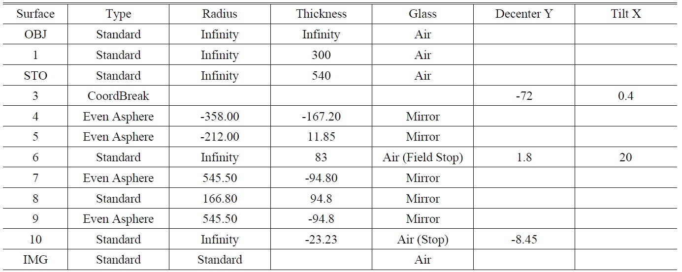
[TABLE 1.] Lens data from ZEMAX (unit: thickness/distance in mm, angle in deg.)

Lens data from ZEMAX (unit: thickness/distance in mm, angle in deg.)
2.2.1. Optical Configuration
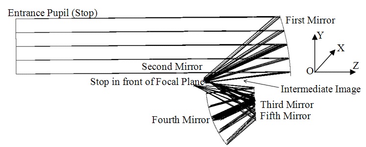
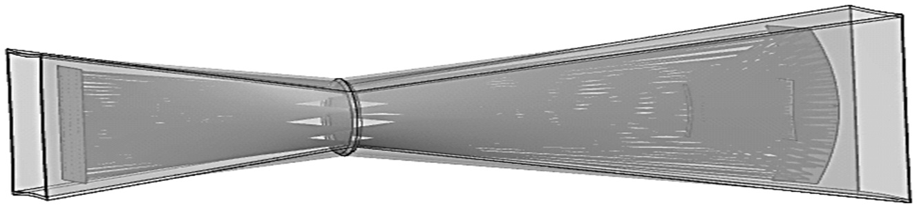
In order to get a telescope for the remote sensing application for the requirements above, an off-axis five-mirroranastigmatic telescope was designed. It is composed of four powered mirrors. The entrance pupil is located in front of the first mirror. The first mirror is a concave aspheric mirror, the secondary mirror is a convex aspheric mirror, the third mirror and fifth mirror have the same convex aspheric mirror parameters at the same place in the Cartesian coordinate system, and the fourth mirror is a concave spherical mirror, which is the largest and the fastest mirror in the telescope.
In the Cartesian coordinate system, the telescope is deviated along the Y axis (-70 mm) and tilted about the X axis (+0.4°). The optical configuration of the off-axis five-mirror-anastigmatic telescope is shown in Fig. 1, the lens data is shown in Table 1 from ZEMAX lens data format.
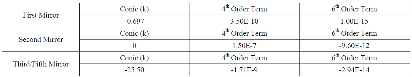
In this telescope, the first mirror, secondary mirror, third mirror and fifth mirror are all even aspheric surfaces, and the surface sag is shown as equation (1).
[TABLE 2.] Parameters for the First, Second and Third/Fifth Mirror

Parameters for the First, Second and Third/Fifth Mirror
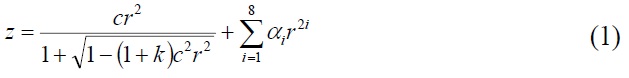
where c is the curvature (the reciprocal of the radius), r is the radial coordinate in lens unit, k is the conic constant, and
The even aspheric surface parameters for the first mirror, second mirror and third/fifth mirror are shown in Table 2.
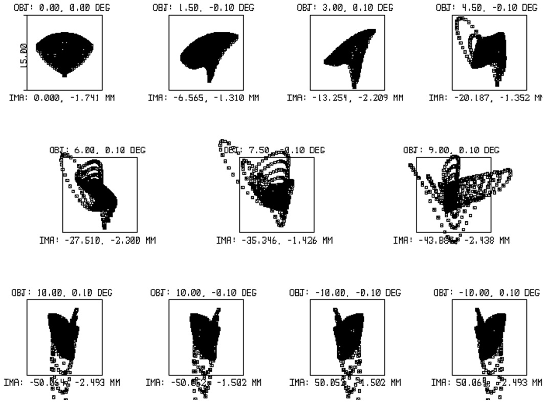
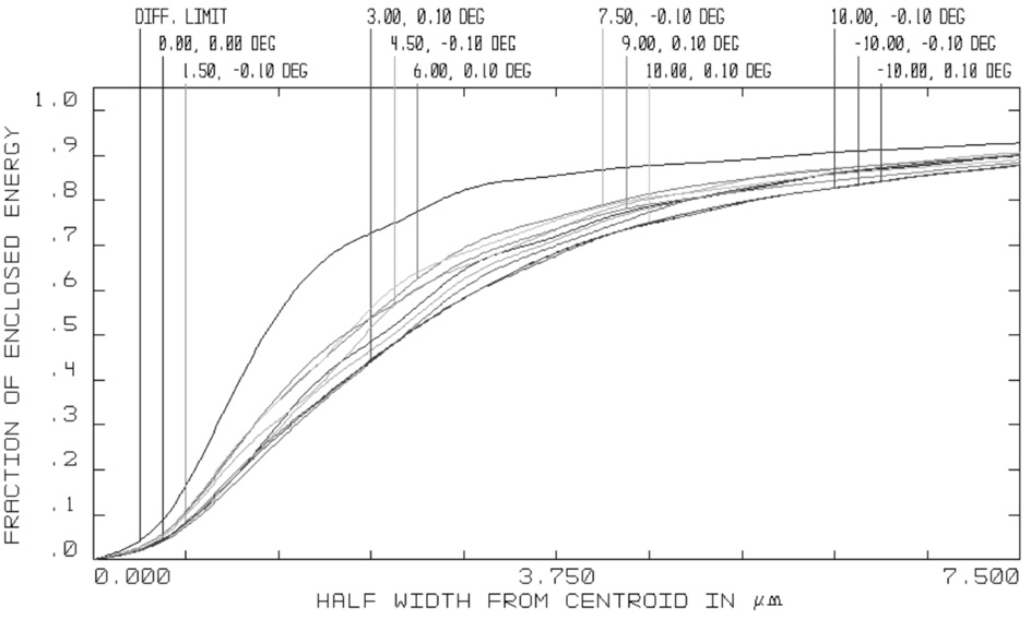
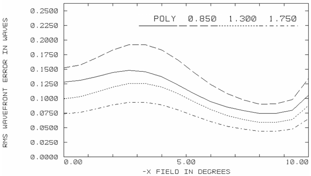
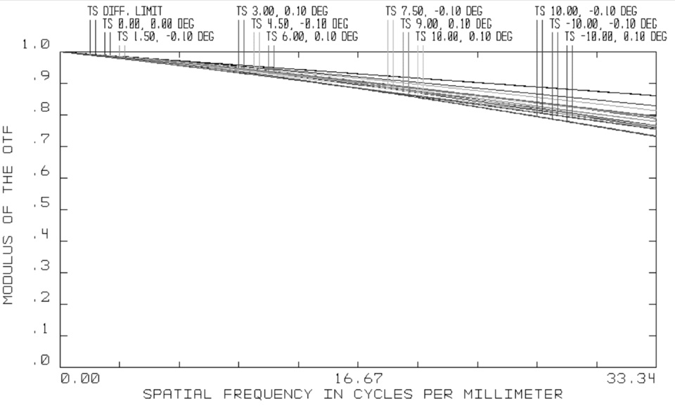
The image quality is evaluated by spot diagram, RMS wavefront error in wave, modulator transfer function (MTF) and ensquared energy. The figures are shown in Fig. 2, Fig. 3, Fig. 4 and Fig. 5 respectively. The Airy Disk diameter is 10.48 μm with wave length of 1.75 μm, the dimension of a pixel is 15 μm×15 μm, and the maximum RMS radius for the spot diagram is 3.76 μm, which is shown in Fig. 2. In Fig. 3, the maximum RMS wavefront error is less than 0.20λ. In Fig. 4, the minimum MTF is
0.7433 at the Nyquist frequency as 33.34 cycles per millimeter. In Fig. 5, the minimum ensquared energy is 87.76%, and the ideal ensquared energy is 92.74% within a pixel. From
the evaluation, we can know the image quality is near the diffraction limit.
2.2.2. Detectors
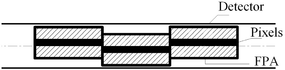
The size of the image plane is 88.16 mm×0.87 mm. The detector can be chosen as 5888×5 with 23 pieces of NIR lined FPA (focal plane array) detectors with 256×5 image format. The geometrical relationship for the FPA detectors is shown in Fig. 6.
2.2.3. Methods to Restrain the Stray Light
In order to improve the image quality, the stray light should be restrained by methods such as setting a field stop, a stop in front of the focal plane, a baffle in front of the third mirror and using the narrow-band pass filter to choose the spectral range.
Field Stop
The field stop is located near the intermediate image.
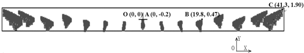
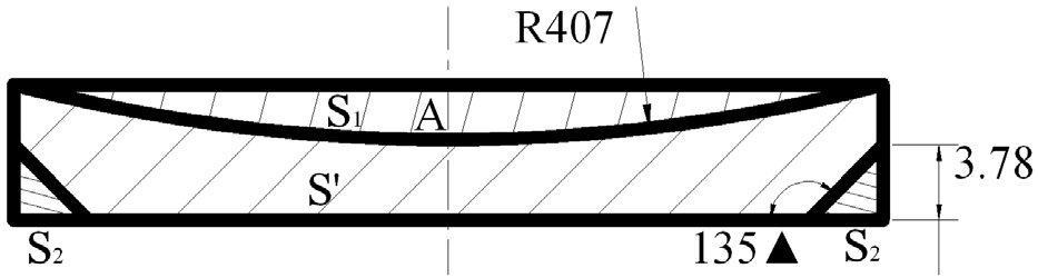
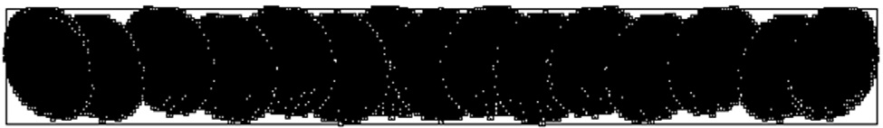
The distance from the field stop to the second mirror is about 12 mm along the Z axis between the second mirror and the third mirror, and the field stop is tilted about the X axis by 20°. The plane of the intermediate image is deformed by aberrations with the wide FOV which is shown in Fig. 7. If the field stop is designed without consideration of the deformation, the dimension of the rectangular field stop will be 84 mm×4.4 mm, and the area of the ideal stop will be increased. Then more stray light which is out of imaging field of view will go through the field stop and decrease the image quality.
The ray footprints with the largest field of points as (±10°, ±0.1°) will deviate from the level of ray footprints along the Y axis compared with the points as (0°, ±0.1°). The differences are shown in Fig. 7.
From the information of the data about the field stop, we can suppose the bent line is a part of a circle, and the curvature of the circle can be gotten from equation (2).

where x and y are the coordinates of intermediate image plane in the Cartesian coordinates; Δy is the deviated distance along the y axis; R is the radius of the bent line.
With the data of point A (0,-0.20), B (19.80, 0.47) and C (41.30, 1.90) in the Cartesian coordinates in Fig. 7, R can be gotten from equation (2) as about 407 mm, then the area

The
If a 84 mm×4.4 mm rectangular stop is simply used as the field stop, then the ratio of increased area to the area of ideal field stop is

That is to say there will be more than 22.8% area to let stray light go through the field stop. That may decrease the image quality sharply. So the field stop should have an arc of radius (407 mm).
Stop in Front of the Focal Plane
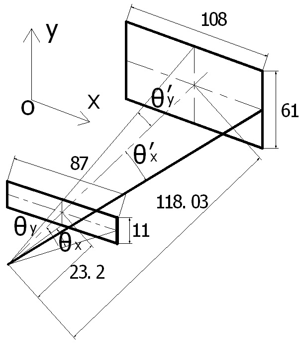
The stop in front of the focal plane is about 23.2 mm to the focal plane. It is a rectangular stop with dimension of 87 mm × 11 mm as shown in Fig. 9. Since it is not a Lyot stop in the telescope, it will give a large half angle
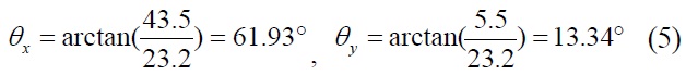
Since the mirrors have finite dimensions in the telescope, and the third mirror and the fifth mirror have the same parameters at the same place with 108 mm × 61 mm dimension, then the other type of half angles will be

Where 54 is the half dimension of the fifth mirror (and the third mirror) in the X direction for field of view point (0, 0), and 30.5 is the half dimension of the fifth mirror (and the third mirror) in the Y direction for field of view
point (0, 0); the data 118.03 is the distance from focal plane to the fifth mirror.
From the equations (5) and (6), we can know that with the help of the stop in front of the focal plane and the finite dimension of the fifth mirror (and the third mirror), the angles
Baffle for the Telescope
The baffle should be designed to restrain the non-imaging light. The baffle is composed of three parts: one part is in front of the stop (entrance pupil), one part is between the stop (entrance pupil) and the first mirror without obscuration in the optical path, the other is between the second mirror and the third mirror. The length of part one is three times the diameter of the entrance pupil. The inner surface of the baffle is the outline of the imaging beams. And the baffle is shown in Fig. 11.
Narrow-band Pass Filter
The spectral range is 0.85-1.75 μm. In the reflective telescope, the optical efficiency is high for all wavelengths. In order to choose the NIR spectral range only, there will be a narrow-band pass filter in the FPA to filter other spectral range. And the tolerance of spectral range for the narrow-band pass filter is ±2%, that is to say the real spectral range is 0.85±0.018-1.75±0.018 μm. Then most of the non-imaging light will be kept out of the detector.
With the help of the baffle, the field stop and the stop in front of the focal plane, only a little stray light can get to the focal plane; the narrow-band pass filter will just let the imaging spectral range pass through it to give signals by the detectors, so that most of fog can disappear in the image.
An off-axis five-mirror-anastigmatic telescope is presented in this paper. It is composed of four powered mirrors in the optical path. The strip full FOV is 20°×0.2°,the effective focal length is 250 mm while the entrance pupil diameter is 100 mm. The image quality is near diffraction limited with spectral range 0.85-1.75 μm. The field stop near the intermediate image, baffle in front of the third mirror, stop in front of focal plane and the narrow-band pass filter will restrain the stray light to reduce the fog in the image. The telescope can be used as an advanced optical instrument for NIR remote sensing.