Carbon nanofibers (CNFs) are used as fillers in nanocomposites. Carbon nanotubes are a type of CNF. CNFs are electrically conductive, and resins filled with CNFs are also conductive. Many researchers have studied the applicability of CNFs in functional materials [1-16]. For example, electromagnetic shielding using a CNF-based composite [1], and an electrical resistance-based sensor [3,4] have been developed.
It is well known that the CNF-based composites are electrically conductive when the CNF volume content is as low as a few percent [5-15]. This is a dramatically low filler content requirement, when compared with the required content of conventional fillers, such as carbon black [14]. The reason for this is that the CNF diameter is small, and the CNF shape has a high aspect ratio. Therefore, the electrical conductivity can be produced without adversely affecting the mechanical properties of the resin. When an elastomer is adopted as the matrix, then a conductive elastomer can be produced [15]. When both the flexibility and the conductivity of this material are used, a large strain sensor based on the change of resistivity may be produced, and strain in membrane structures, such as hot air balloons or solar sails, may be measured; conventional strain gages cannot measure these strains.
In this study, a patch-type large strain sensor based on the resistivity change in a CNF/elastomer composite was proposed, and the measurement limits of the sensor were investigated experimentally. Also, the validity of the sensor in terms of the deformation followability was demonstrated, by comparison with a traditional patch-type strain gage.
2. Large strain sensor using CNF/elastomer composite
2. 1 Fabrication of the CNF/elastomer composite
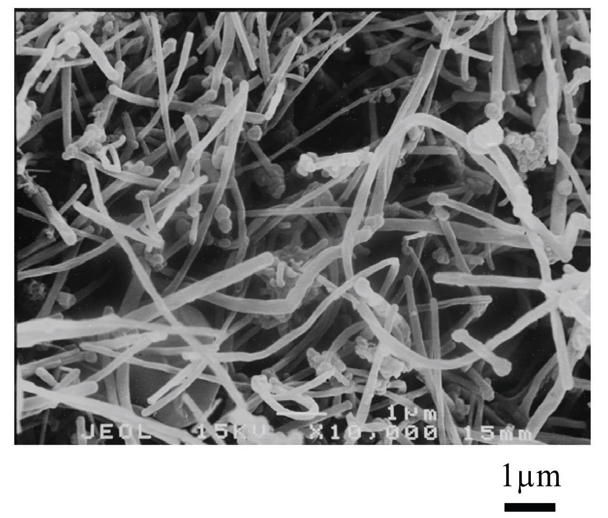
In this study, vapor grown carbon fiber (VGCF) supplied by Showa Denko K.K. was used as the CNF filler. The material properties are shown in Table 1. VGCF is a kind of carbon nanofiber with a diameter of approximately 100 nm. VGCF was discovered by Oberlin et al. in 1974 [17]. VGCF is graphitized by heating at high temperatures of 2000-2800℃, and its structure is the same as that of multi-walled carbon nanotubes. The aspect ratio of VGCF is smaller than that of general carbon nanotubes. VGCF therefore has good dispersion properties, when it fills in the matrix. A picture of VGCF produced by scanning electron microscopy (SEM) is presented in Fig. 1.
[Table 1.] Attributes of VGCF.
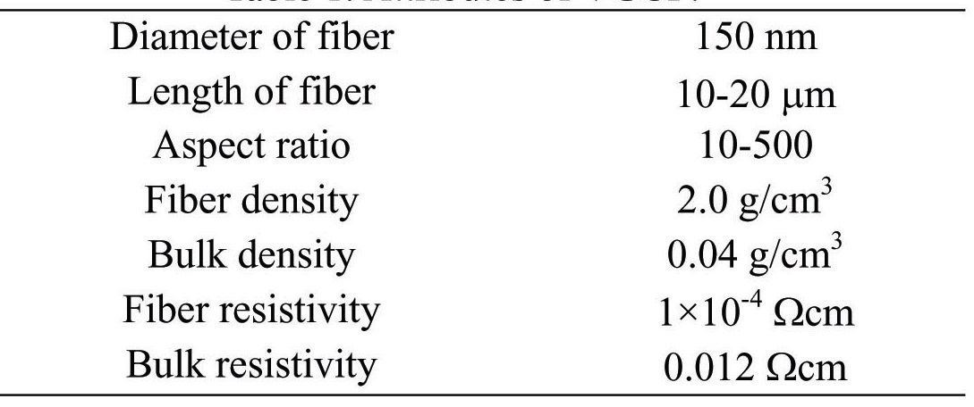
Attributes of VGCF.
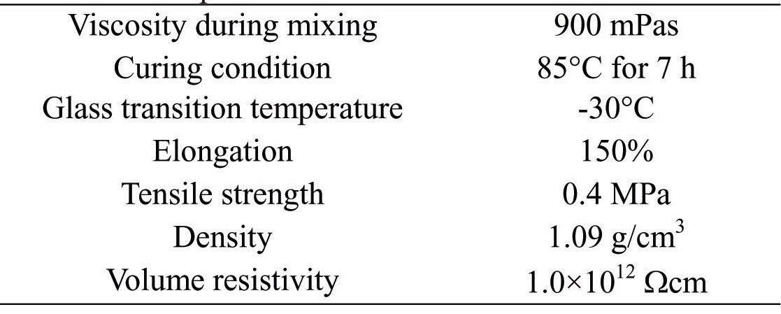
[Table 2.] Properties of ME-113/XH-1859-2 elastomer.

Properties of ME-113/XH-1859-2 elastomer.
A flexible epoxy (ME-113/XH-1859-2, Nippon Pelnox Corp.) was adopted as the elastomer for the composite. The epoxy is fabricated by mixing resin with a hardener, and has a high flexibility property, with elongation of 150%. The material properties are shown in Table 2.
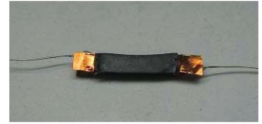
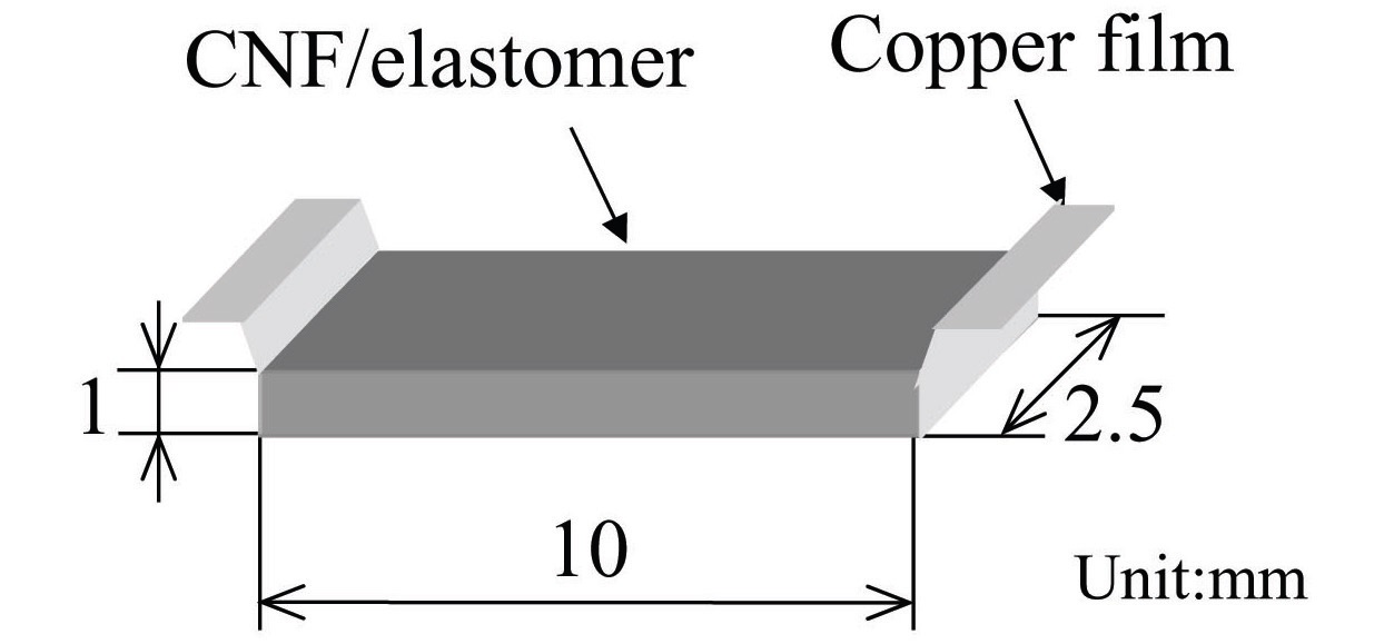
The configuration of the proposed large strain sensor is presented in Fig. 2. A patch-type structure similar to that of traditional metal-foil strain gages was applied. The copper foil electrodes were bonded by co-curing both ends of the CNF/elastomer sensor. The CNF volume fraction is 6.0 weight percent (wt.%) with consideration of the resistivity. In the case of the composite in this study, filler content of more than 2 wt.% is required for electrical conductivity to occur.
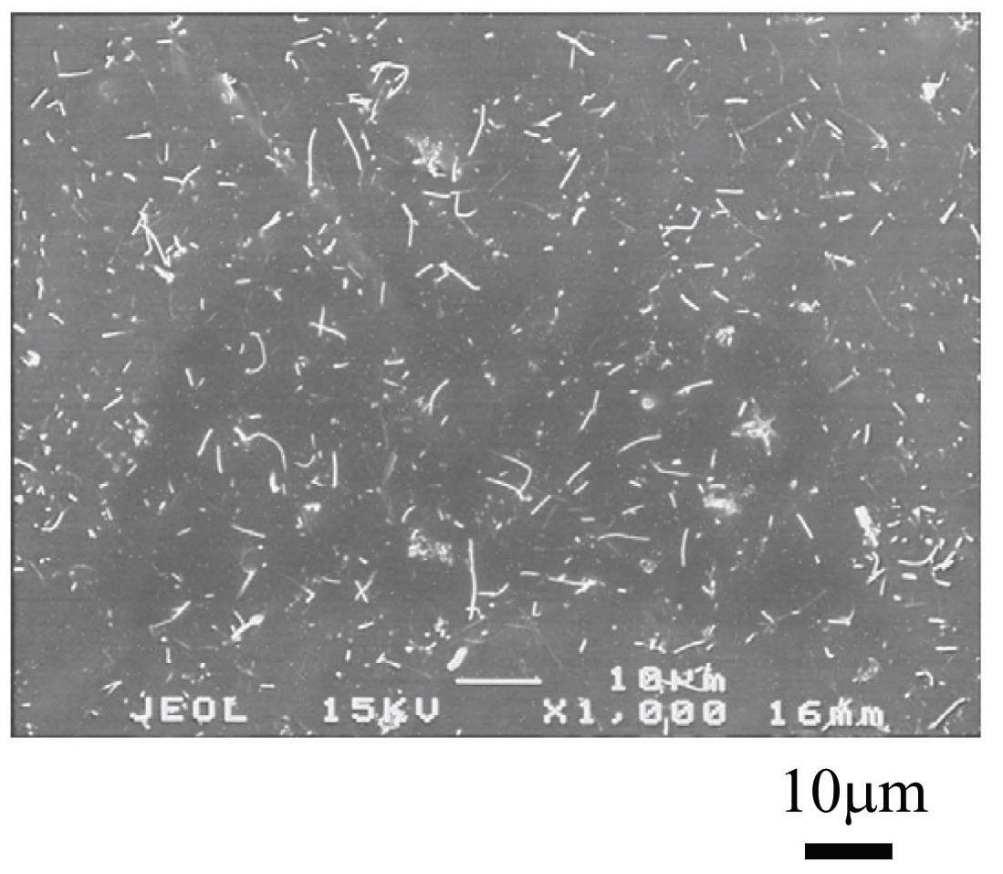
The fabrication procedure for the proposed sensor is as follows. First, the CNFs were dried at 130℃ for 3 h. Next, the epoxy resin, the hardener and the CNFs were mixed in a planetary-type mixer (NBK-1, Nihonseiki Kaisha Ltd.) at 2000 rpm for 10 min. Degassing and dispersion were
conducted simultaneously by the mixer. Then, the mixture was poured into a silicon mold, and cured with electrodes in a furnace at 85℃ for 7 h. After curing, the material was cut into the shape shown in Fig. 2, and a lead wire was soldered to the electrodes. Good dispersion of the CNFs was achieved using this procedure, as confirmed by the SEM image shown in Fig. 3. A picture of the fabricated large strain sensor is shown in Fig. 4.
2. 2 Test method for large strain measurement
The strain measurement limitations of the fabricated large strain sensor were investigated by a quasi-static tensile test.
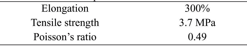
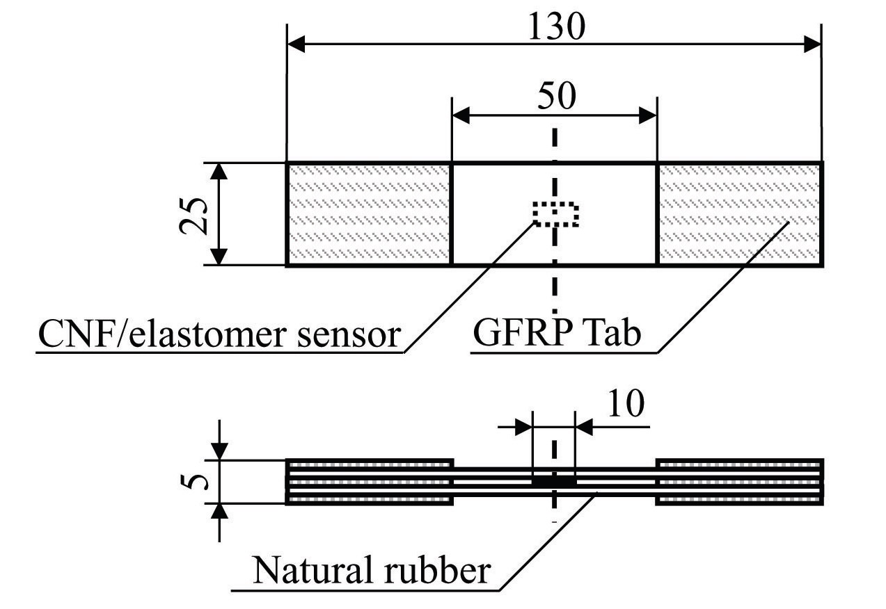
Two types of specimens were prepared. The shapes and dimensions of these specimens are portrayed in Fig. 5 and Fig. 6. The specimen shown in Fig. 5, which is named “type A”, has a structure where the sensor is sandwiched by rubber plates. The properties of these rubber plates are shown in Table 3. The type A specimen is symmetrical, and the effects
[Table 3.] Properties of natural rubber.

Properties of natural rubber.
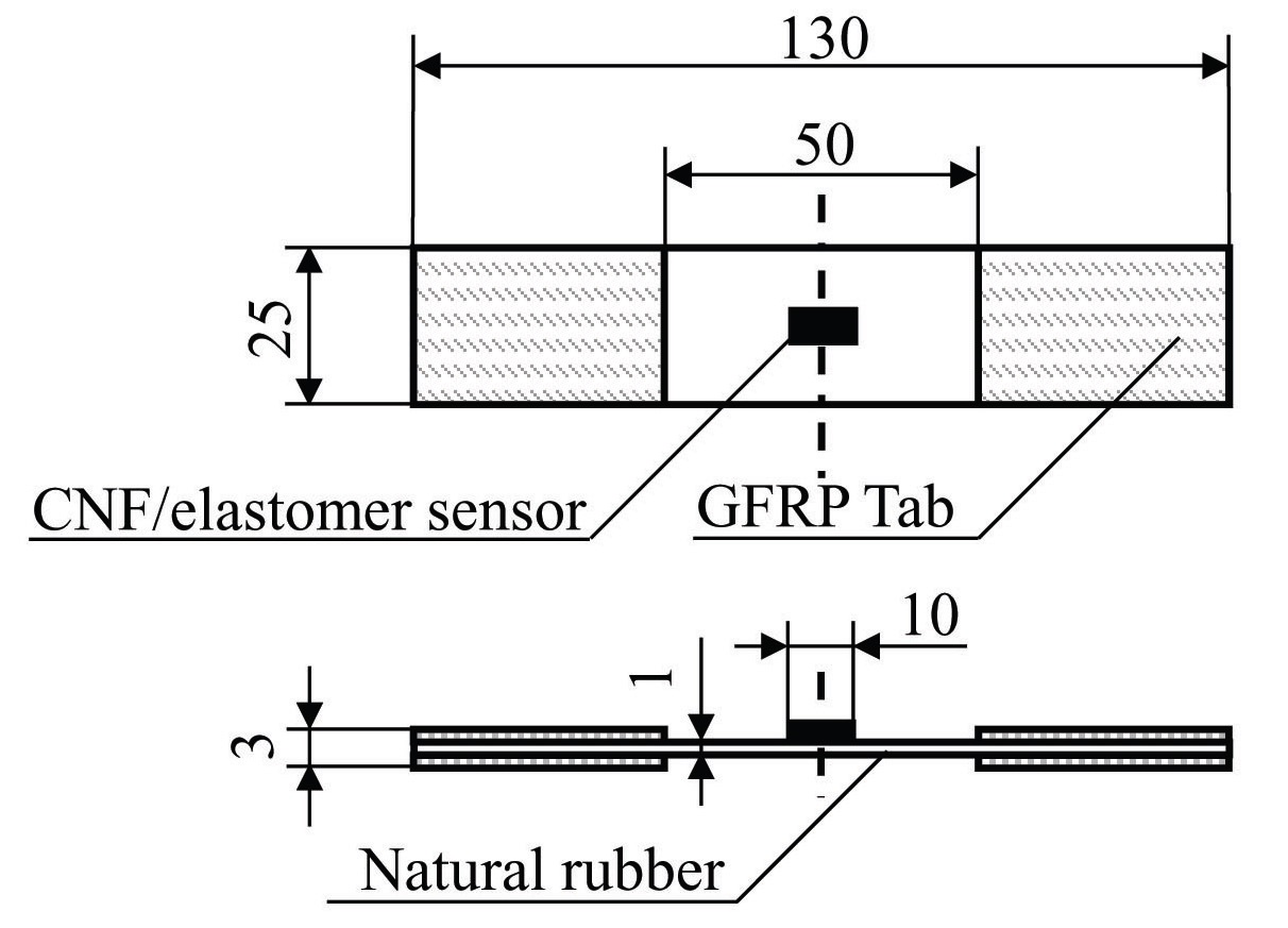
of bending deformation can be extinguished during the tensile tests. The specimen shown in Fig. 6, which is named “type B”, is fabricated by attaching the sensor to one side of the rubber plate,assumed to be applied to the actual structures. As an adhesive, a flexible epoxy was used, which is the same material as that of the matrix, and the sensor was attached by covering it, together with the electrodes.
The test method is as follows. A tensile load was applied in the longitudinal direction of the specimen. The electrical resistance change of the sensor was then measured, using an LCR meter (LCR HiTester 3522, Hioki E.E. Corp.). The strain was measured, based on the change in the gage length marked on the rubber plate. The crosshead speed was 0.5 mm/min. Tensile loading was applied continuously, up to the failure point of the sensor.
2. 3 Test results and discussion
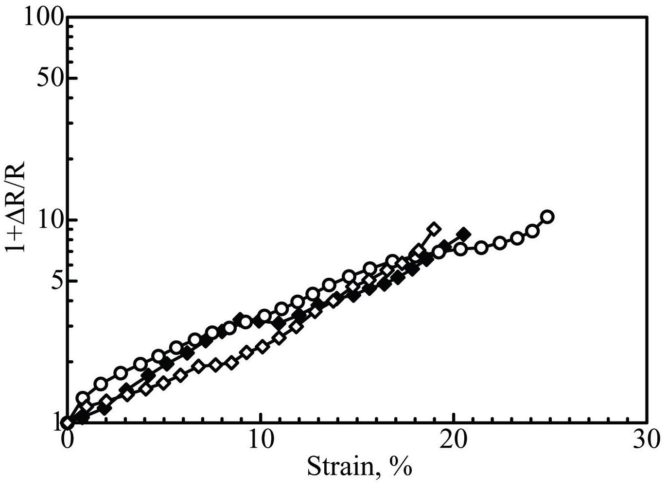
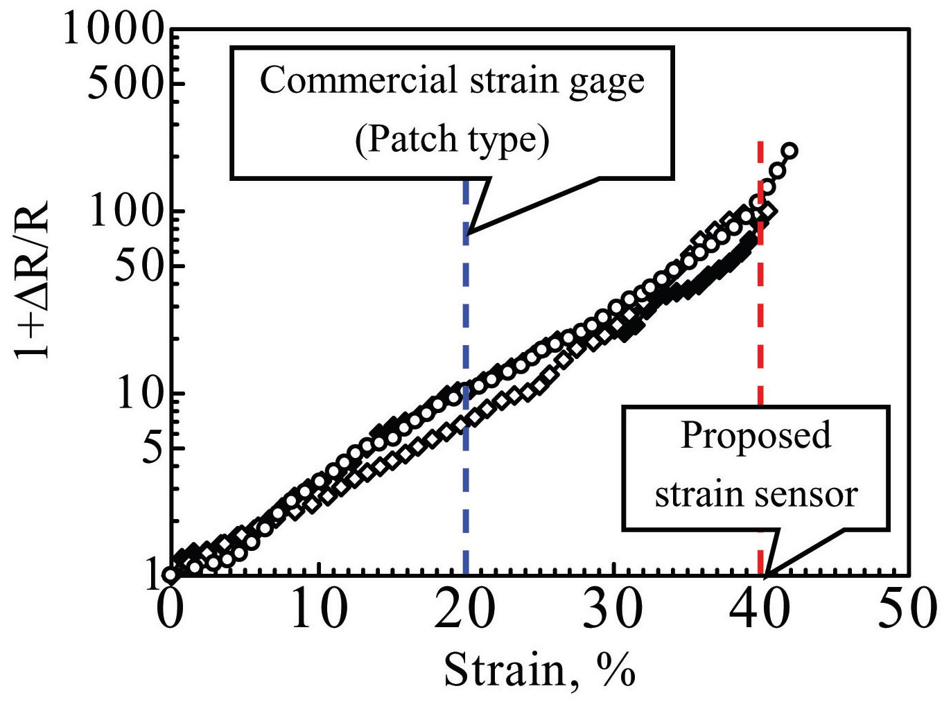
Test results for the type A specimens are shown in Fig. 7, and those for the type B specimens are shown in Fig. 8. The electrical resistance change results were plotted on logarithmic scales, in each case. The authors have previously reported that the electrical resistance of CNFbased composites under tensile strain conditions changes exponentially, and the mechanism of this behavior can be described based on percolation theory and tunneling effects [18]. The tests were conducted with three specimens for each of the two types of specimen, and the results for both types followed similar curves. The initial values of the electrical resistance of the sensors are 80 kΩ, 113 kΩ and 120 kΩ for type A, and 62 kΩ, 80 kΩ and 130 kΩ for type B. The initial electrical resistance values of each sensor are different, because a slight difference in the CNF content can cause a significant change in the electrical resistance. The failure strain was defined as the strain at the time of a sudden increase in electrical resistance, caused by sensor failure. The failure strain for type A was approximately 20%, while that for
type B was approximately 40%, which greatly exceeded the limit for conventional metal foil-based strain gages of 20%. The proposed large strain sensor can therefore measure up to twice the strain limit of conventional strain gages.
Specimen failure occurred at the adhesive area of the electrodes, as confirmed by visual observation. For a type A specimen, the sensor constraint is larger than that of type B, because of the sensor’s sandwich structure. This constraint leads to locally excessive strain around the electrodes, and, therefore, the type A specimen failed at relatively small strain values, when compared with the type B specimen.
When comparing the results shown in Fig. 7 and Fig. 8, the values of the electrical resistance change tended
to be quantitatively similar. This means that the effect of bending deformation is also negligible, in the case of the unsymmetrical specimen of type B. The reason for this behavior is that the sensor rigidity is sufficiently small, relative to that of the rubber plate. In other words, the proposed sensor can be applied to low rigidity materials, such as rubber or flexible materials.
2. 4 Comparison with the conventional large strain gage
Traditionally, metal-foiled large strain gages are used to measure the plastic deformation of metals or plastics. The CNF/elastomer strain sensor proposed in this study can measure up to 40% strain, which is twice the limit of conventional strain gages. In this section, the CNF/elastomer strain sensor is compared with conventional strain gages, in terms of deformation followability.
For comparison, a metal-foiled large strain gage (KLM- 6-120-A9) supplied by Kyowa Electronic Instruments was adopted as the conventional strain gage. The strain gage was attached to the type B specimen as a substitute for the proposed sensor, and the gage was bonded using a special adhesive (EC-30, Kyowa Electronic Instruments). Three different kinds of specimen were prepared: a type B specimen attached to the proposed CNF/elastomer strain sensor, a specimen attached to the metal-foiled large strain gage, and a specimen without any sensor (rubber plate-only case).
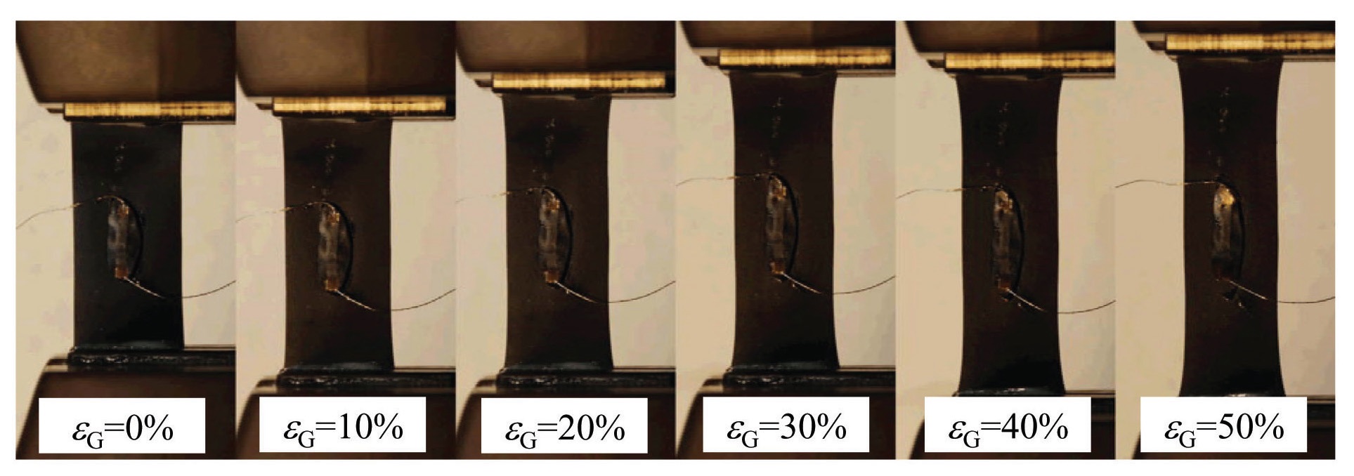
Tensile loading was applied in the longitudinal direction of the specimens. Strain was measured at every 2.5 mm of
displacement, and a photograph was taken at every 5.0 mm of displacement. Here, the gage length of the specimen used to measure the strain is 50 mm, and thus a displacement of 2.5 mm is equivalent to an
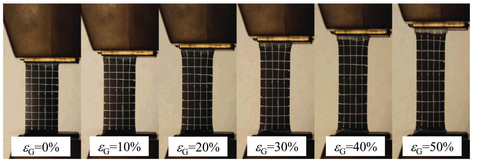
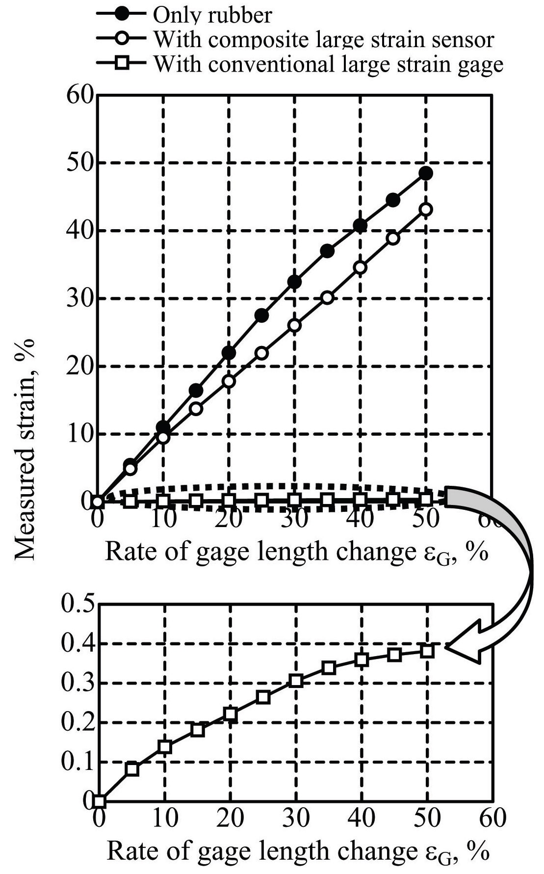
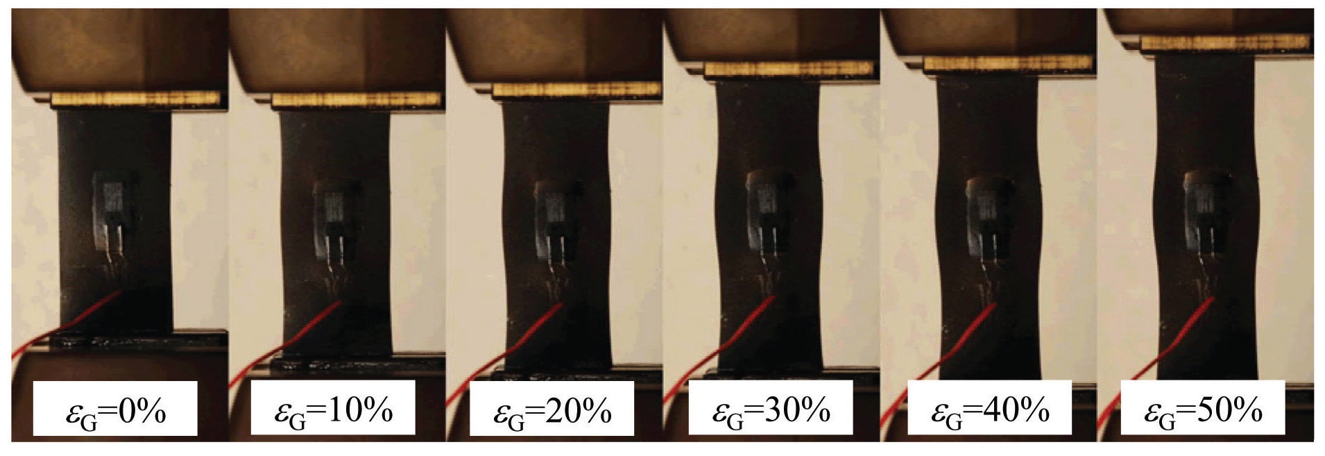
The measurement results are shown in Fig. 9, Fig. 10 and Fig. 11. Figure 9 shows a photo of the case of the proposed CNF/elastomer strain sensor, Fig. 10 presents the case of the metal-foiled large strain gage, and Fig. 11 shows the rubber plate-only case. The metal-foiled large strain gage interfered with the deformation of the rubber plate. However, the proposed CNF/elastomer strain sensor
followed the deformation of the rubber plate, because of its flexibility. Figure 12 plots the relationships of the measured strain versus the gauge length change
A patch-type large strain sensor using the resistivity change of a CNF/elastomer composite was proposed. The measurement limit of the sensor was experimentally investigated, and was found to be 40%, which was far greater than the limit of conventional metal-foiled strain gages. The CNF/elastomer large strain sensor was also compared with conventional strain gages, in terms of their deformation followability. The results for the CNF/elastomer strain sensor indicated good followability to the rubber plate. The proposed CNF/elastomer large strain sensor could be used to measure strain in flexible materials, while conventional strain gages cannot.