A plate like beam can be thought of as a two-dimensional narrow structural member that can take membrane stresses. In usual structural analysis, these are taken as a simplified one-dimensional beam element. However, considering the same as two-dimensional, it enhances the load carrying capacity, as the beam element carries an additional in-plane load, giving rise to improved strength to weight ratio.
The study of the static and dynamic response behaviour of plate like beam type structural elements under the in-plane harmonic load is of importance. The in-plane load significantly affects the response behaviour. As the magnitude of in-plane compressive load increases, the frequency of vibration reduces and at a critical buckling load the frequency becomes zero. Periodic in-plane loads induce dynamic instability in the form of resonant transverse vibrations. This phenomenon is known as parametric resonance. The instability regions of parametric resonance consist of a range of values for loading parameters for which instability occurs. Dynamic instability can occur when the excitation frequency is related to one of the natural frequencies of the system. This is called simple resonance. When excitation frequency is related to more than one natural frequency, the instability phenomenon called combination resonance occurs (Bolotin, 1964).
Extensive study has been done on the static and dynamic behaviour of structural elements. Sahu and Datta (2007) have made an excellent review on the works available in the literature, both for isotropic and composite materials.
Damages or flaws are almost unavoidable in any structure at some stage of its operating life span. The presence of damage significantly affects the buckling, vibration and parametric instability behaviour of the structural element. Damage modelling is usually based on the stiffness loss. Modelling of damage in anisotropic materials, such as laminate composites is done through the continuum damage mechanics approach. This method is helpful in describing the deterioration of material based on the onset or initiation of damage, such as micro cracks (Voyiadjis, 2005). Talreja (1985) introduced damage by describing a set of vectors to represent damage on various directed planes in the composite material. A continuum mechanics based model of cracks was proposed by Abdelrahman and Nayfeh (1999). Valliappan et al. (1990) developed a finite element model of anisotropic damage based on the structural reduction factor. The formulation has a broader scope of applications because of the elegance and simplicity of constitutive relations and non-symmetry of the damaged stress tensor.
A composite damage model called Damage Mesomodel for Laminates (DML) was proposed by Ladeveze and LeDantec (1992). This model takes into account the characteristic differences between the damaged plies under tensile and compressive stresses. Murari and Upadhyay (2008) have worked on a modification of DML which takes into account the damage at the microlevel. Pidaparti (1997) computed the free vibration and flutter characteristics of a composite plate considering the aeroelastic effects. The author establishes that the formulation proposed by Valliappan et al. (1990) has more influence on the free vibration and parametric resonance characteristics than that by Talreja (1985). Under suitable constraints the formulation proposed by Valliappan et al. (1990) reduces to the isotropic damage formulation proposed by Prabhakara and Datta (1993).
Considerable amount of works are available in literature regarding the stability of beams, plates and shells under various loading conditions including the in-plane harmonic load, follower load and transverse harmonic loads (Sahu and Datta, 2007). The importance of the plate like beam structure was discussed. A void exists in literature when it comes to the stability behaviour of such structures subjected to the in-plane harmonic load. In the present work, a generalized anisotropic damage formulation was twinned to the plate like beam problem and studies on free vibration, buckling
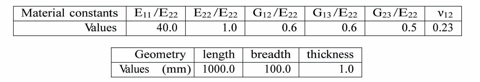
Material properties of each composite layer [Reddy (1984b) and Moorthy et al. (1990)] and dimension of the plate like beam used for present study.
and dynamic instability characteristics were made on isotropic and composite structures. The effects of damage orthogonality, damage intensity, damage size and its location on static and dynamic characteristics have been investigated.
The advantage to the method is that the formulation considers the in-plane membrane effect of the plate in the beam problem. The presence of damage in the plate like beam alters the in-plane stress distributions. The beam formulation in this paper takes care of the effects of damage on the buckling, transverse vibration and parametric resonance behavior of the structural elements, considering the in-plane non uniform stress distribution, due to various damage parameters. These results will provide information regarding structures pertaining to aerospace applications for which weight is a prime design parameter.
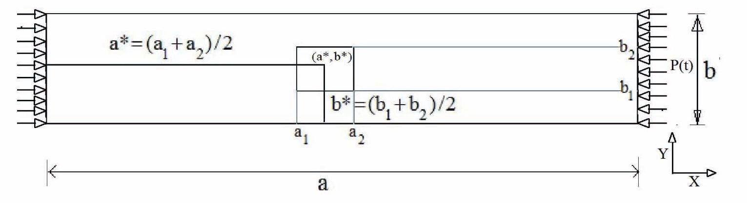
A plate like beam structure (Fig. 1) under in-plane harmonic load, P(t) is modelled by using the finite element method.
The harmonic loading P (t) is expressed as (Bolotin (1964))
p(t)=Ps+Ptsin(Ωt)
where,
Ps=αPcr=static component of the parametric loading
Pt=βPcr=dynamic component of the parametric loading
Ω=frequency of the harmonic loading
α= static load factor
β= dynamic load factor
Pcr=critical buckling load of plate like beam.
values for
A shear correction factor, K=5/6 [Moorthy et al. (1990), Udar and Datta (2007)] has been chosen to accommodate the effect of non-uniform strain distribution along the thickness. To validate the formulation’s applicability for isotropic materials with results available in literature, the isotropic material was merely treated as a special case of composite material with
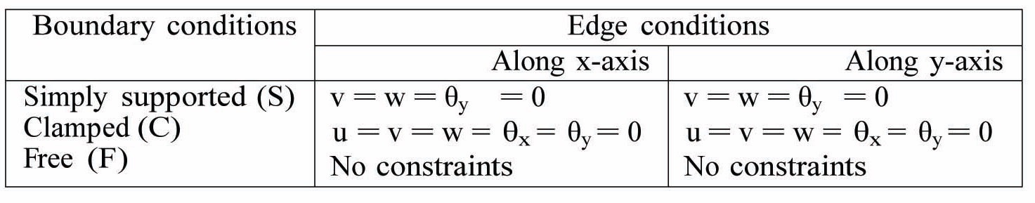
In the current study, the two ends of the plate like beam can have any of the three boundary conditions namely simply supported, clamped and free, denoted by symbols S, C, and F, respectively. The other two edges are free. The numerical constraints applied against each boundary condition are tabulated in Table 2.
In a two dimensional structure, viz. a thin plate like beam, anisotropic damage is parametrically incorporated into the formulation by considering the parameter Гi. This parameter is essentially a representation of reduction in effective area and is given by
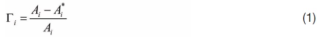
Where

is the effective area (with unit normal) after damage and are the three orthogonal directions. For a thin plate like beam only Г1 and Г2 need to be considered. Г1 represents the damage in the direction of the fibre while Г2 refers to orthogonal damage. This method of parametrically modelling damage in any anisotropic material was proposed by Valliappan et al. (1990). Using this formulation, a damaged stress-strain matrix for a two dimensional laminate is written as

[Table 2.] Boundary conditions and Numerical constraints

Boundary conditions and Numerical constraints
[Table 3.] Non-dimensionalization of parameters
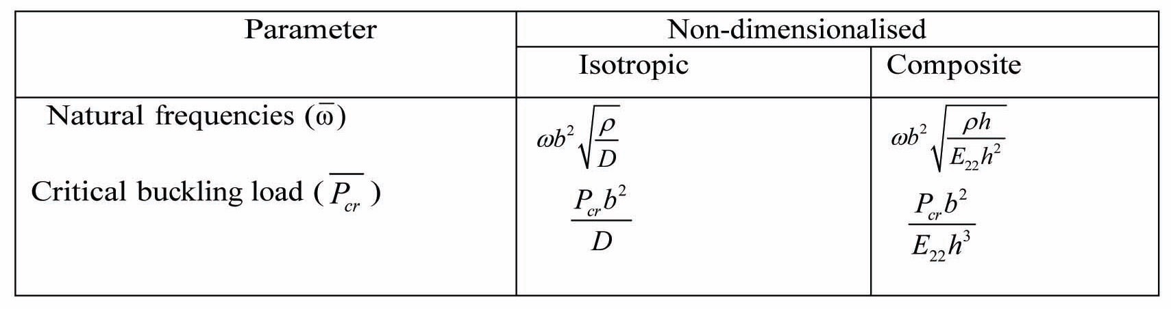
Non-dimensionalization of parameters
where,
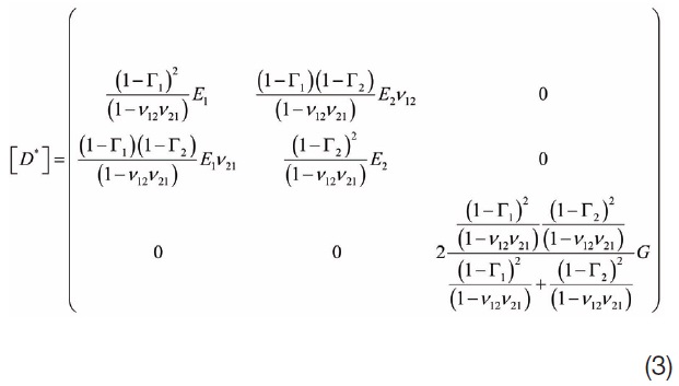
This relation is then transformed to the general coordinate system as with the general undamaged cases. It can also be noted that by constraining the values of Г1 and Г2, one can yield a damage formulation for an isotropic material as proposed by Prabhakara and Datta (1993).
The damaged area has been considered as a square patch (Fig.1). The parameters Г1 and Г2 determine the extent of damage. The parameter ψ denotes the area of the damage patch, while
2.2 Non-dimensionalization of parameters
For convenience of analysis and comparison, the model parameters and results are presented in non-dimensional form leaving them independent of geometry and material property values. The non-dimensionalization parameters are presented in Table 3 [Reddy (1984a), Moorthy et al. (1990)]. The parameter used to non-dimensionlize isotropic problems is the flexural rigidity of the panel and is given by D=
A generalized equation of motion can be written to generate various classes of problems.

If
Using modal transformation, Eq.(4) is modified in the following form [Nayfeh (1981), Udar and Datta (2007)]

where the terminologies are explained in the above references.
Eq.(5) is solved using the method of multiple scales (MMS) (Nayfeh, 1981) to obtain the boundaries of the simple and combination parametric zones of instability. When the frequency of the excitation is close to the sum or difference of two natural frequencies of the system, a combination resonance of the summed type or difference type exists between the various modes. The nearness of Ω to

where, σ, is obtained from the solution of the following quadratic equation,

where, the constants A, B and C are explained in ref. Nayfeh (1981).
The two roots of Eq.(7) correspond to two boundaries of the dynamic instability region. The case
2.4 Definition of ‘onset’ and ‘width’
For tabulating and plotting the characteristics and variation of the simple and combination resonance instability regions due to various factors, the traditional frequencyratio against dynamic load factor curves is inadequate. In order to do so, two terms are introduced ? ‘onset’ and ‘width’ of an instability region. The onset of any region is the point corresponding to
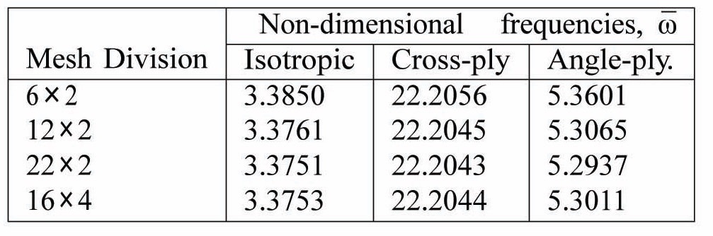
To check the validity of the present finite element formulation for plate like beams, a series of convergence and comparison studies have been carried out. A convergence study is carried out to select the optimum mesh sizes for the purpose of numerical computation. The results obtained from the limiting cases of the formulation are tallied against available results in order to validate the accuracy of the present formulation.
Table 4 shows convergence results for the natural frequencies of a fixed-free isotropic and composite plate like beam. For this study, a mesh size of 22×2 has been chosen.
Table 5 presents non-dimensional free vibration frequencies and buckling loads for isotropic beams under various boundary conditions, and compared them with those reported by Goyal and Kapania (2007). Free vibration frequencies for composite beams are shown in Table 6. The results are in good agreement with Maiti and Sinha (1994).
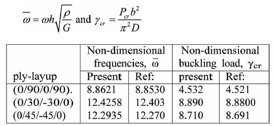
Table 7 lists the non-dimensional free-vibration frequencies and buckling loads for cantilevered, angle-ply composite laminates. The results obtained are in agreement with that presented by Goyal and Kapania (2007). Further, these results are a prerequisite to the MMS formulation that computes the parametric resonance instability zones.
Primary instability regions or the simple resonance zones for a square, which simply supported isotropic plates for different static and dynamic load factors (
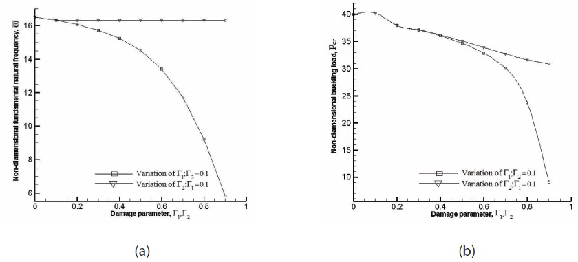
For cases where damage has been considered, the damage parameters, Г1, Г2, ψ and its location on the plate like beam are of importance. The direction of damage with respect to fibre orientation has significant influence in the static and dynamic instability characteristics of the plate like beam. A reduction in stiffness in the direction of fibre influences the buckling, vibration and dynamic instability characteristics more profoundly than a reduction of stiffness occurring in a direction perpendicular to the fibre orientation. So, the damage parameter Г2 is set at 0.1, while the intensity of damage represented by the damage ratio Г1/Г2 is varied from 0.0 to 9.0. A mild damage may be represented with a damage ratio of 0.0 ≤ Г1/Г2 3.0, while heavy damage may be denoted by the range of values, 7.0 ≤ Г1/Г2 ≤ 9.0.
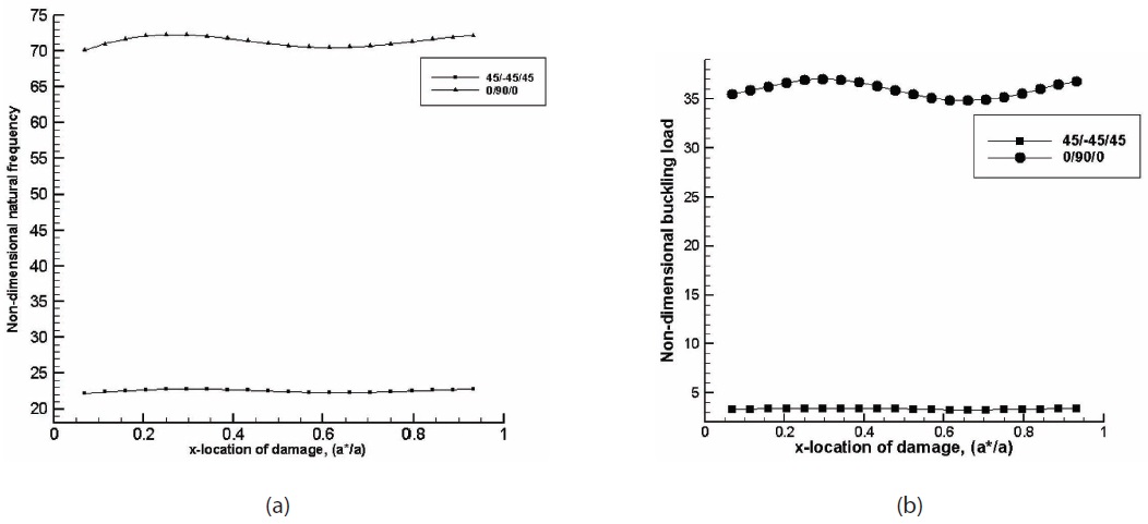
The effect of damage on the dynamics of structure influence vibration and buckling characteristics which affects the dynamic instability behaviour of plate like beam structural elements. Variation of the non-dimensional fundamental natural frequency and buckling load with damage ratio for a C-F (0/90/0) cross-ply composite plate like beam with the thickness ratio (

Convergence study of non-dimensional free vibration fre quencies of cantilevered isotropic (a/b = 10, b/h = 10, E11 = E22 = 70 GP a, G12 = G13 = G23 = 26.923 GPa and ν12 = 0.3), symmetric, cross-ply (0/90/90/0) and asymmetric angle-ply (45/- 45/45/-45) plate like beams. (a/b = 10, b/h = 10, E11 /E22 = 40 GP a, G12 /E22 = G13 /E22 = 0.6 GP a, G23 /E22 = 0.5 GPa and ν12 = 0.25).
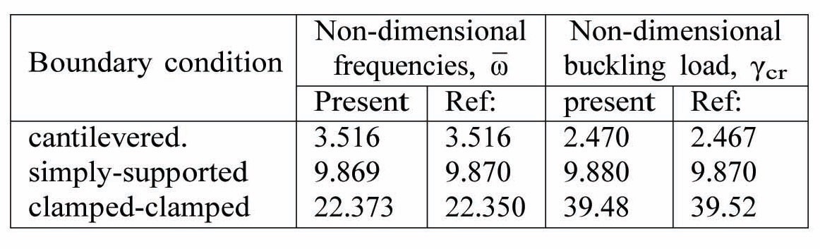
Non-dimensional free-vibration frequencies and buckling loads for isotropic beams under various boundary conditions. a/b=10, b/h=100. The results are compared to those reported by Goyal and Kapania (2007).
of damage reduces the frequency and the buckling load in comparison to the undamaged cases. The general trend of variations is found valid irrespective of boundary conditions applied at the ends of the plate like beam and for different ply orientations.
Figs. 3(a) and 3(b) show the variations of the nondimensional fundamental natural frequency and buckling load with the location of damage for the cross-ply and angleply clamped-simply supported (C-S) plate like beam. It can be observed that both vibration and buckling behaviour improve for the damage position near the simply supported end. Further, the cross-ply plate like beam has better vibration and buckling characteristics compared to the angle-ply configuration. Similar results are also observed for the clamped-free (C-F) composite plate like beam.
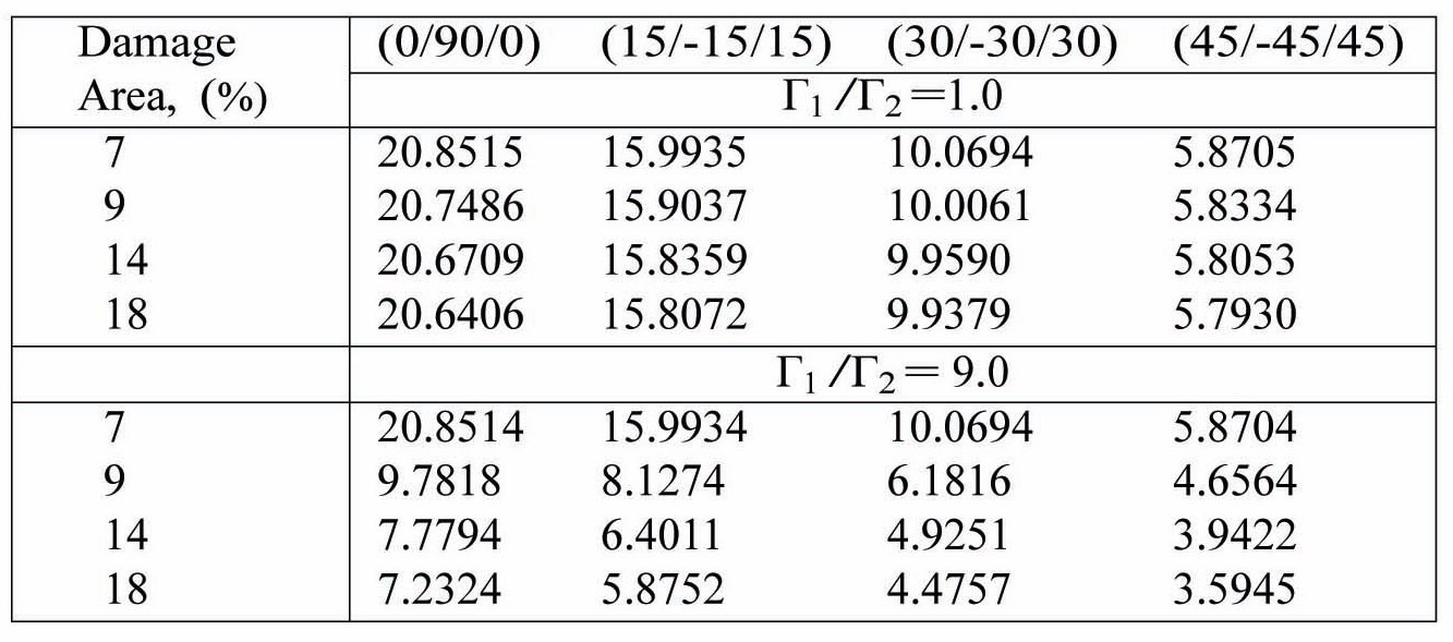
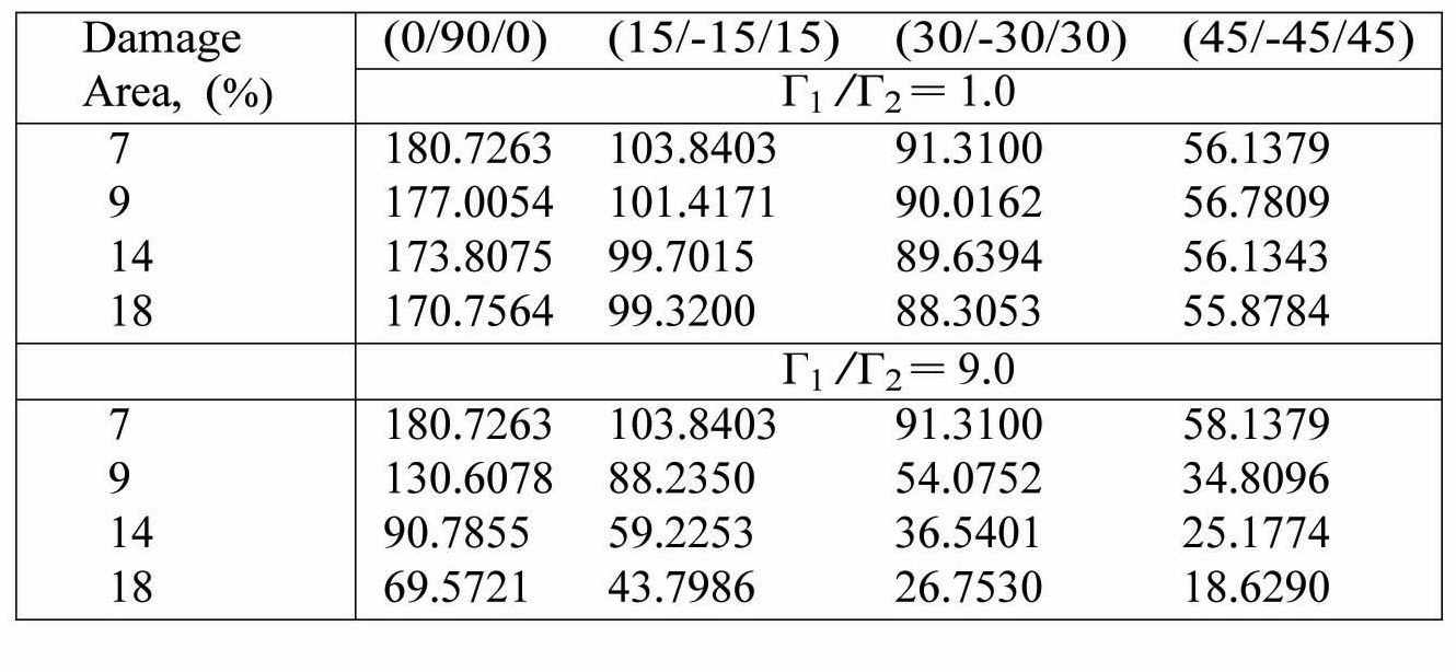
The effects of the damage area for various centrally damaged, cantilevered, composite plate like beams have been obtained. Tables 9 and 10 show the variations of frequency and buckling load for centrally located damage patches of various sizes and having damage intensities of (Г1/Г2) = 1.0 (mild) and (Г1/Г2) = 9.0 (heavy).
The drop in fundamental natural frequency in the heavily damaged case when compared to mild damage is as expected. The fundamental natural frequency drops for all plies as the damage area is increased. Also, the crossply plate like beams (0/90/0) have a higher fundamental frequency than their angle ply counterparts (
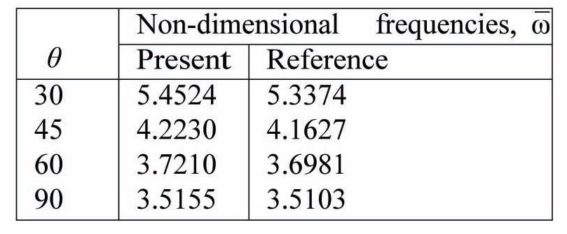
Non-dimensional free vibration frequencies for cantilevered, unidirectional, composite beams. Fibre orientation: (θ/θ/θ/ θ). a/b = 20, b/h = 0.5. The results are compared to those reported by Maiti and Sinha (1994).

Non-dimensional free-vibration frequencies and buckling loads for cantilevered, angle-ply composite laminates. a/b = 60, b/h = 0.5. The results are compared to those reported by Goyal and Kapania (2007). Non-dimensional parameters
physically. The cross-ply plate like beam (0/90/0) has better buckling characteristics than its angle-ply (
Simple and combination resonance type dynamic instability characteristics for the composite plate like beam with variation of damage parameters have been studied, for different static and dynamic load factors of the harmonic
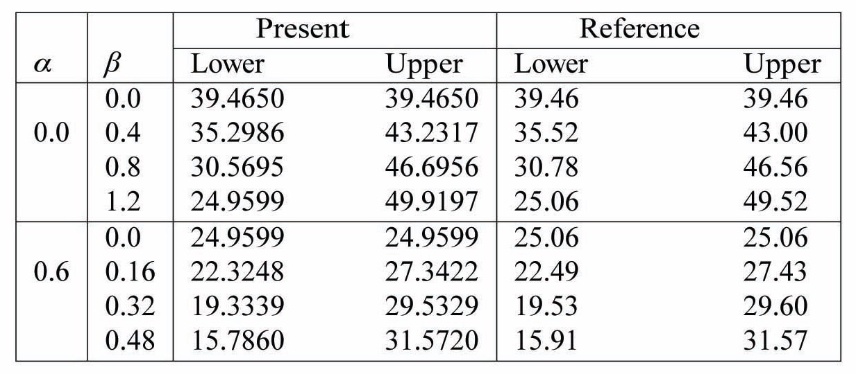
Non-dimensional excitation frequencies corresponding to lower and upper bounds of the primary instability region of a square, simply supported isotropic plate. Thickness ratio, b/h = 100. Load width, c/b = 100. The values have been compared with those reported by Hutt and Salam. (1971).
load. For the present analysis, second order MMS has been used to obtain the zones of instability. The static load factor,
It has been observed that unlike free vibration and buckling characteristics, parametric resonance instability zones are not greatly affected by damage intensity. However, there exist few cases where the change in the intensity of damage influences certain combination resonance zones.
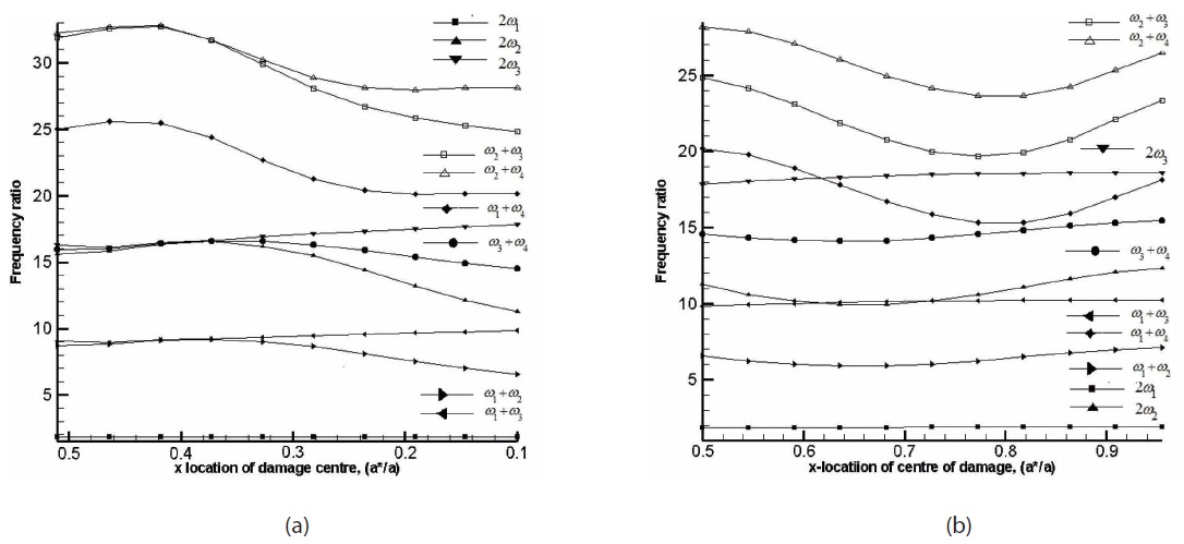
The location of damage has a greater influence on

Variation of non-dimensional fundamental natural frequency with damage area for cantilevered composite plate like beams with thickness ratio b/h = 100. Г2= 0.1.
parametric resonance instability zones than damage intensity. A rectangular damage patch of area, ψ = 14%, is considered and the effect of its location (

Variation of non-dimensional buckling load with damage area for cantilevered composite plate like beams with thickness ratio = 100, Г2= 0.1.
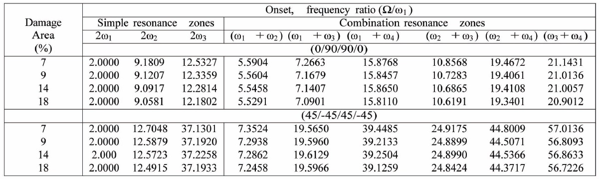
Variation of the onset of simple and combination resonance zones for centrally damaged, cantilevered, cross-ply and angle-ply panels under in-plane harmonic loading. Damage ratio, Г1 /Г2 = 1.0. Г2 = 0.1.
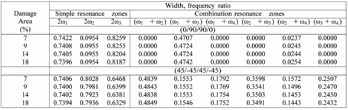
Variation of the width of simple and combination resonance zones for centrally damaged, cantilevered, cross-ply and angle-ply panels under in-plane harmonic loading. Damage ratio, Г1 /Г2 = 1.0. Г2 = 0.1.
i.e. 0.4 ≤ (
The variation of the onset and width of parametric resonance instability zones for cantilevered cross-ply (0/90/90/0) and angle-ply (45/-45/45/-45) under the inplane harmonic load is presented in Tables 11 and 12, respectively. It can be observed that for the cross-ply case, only
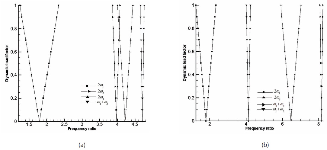
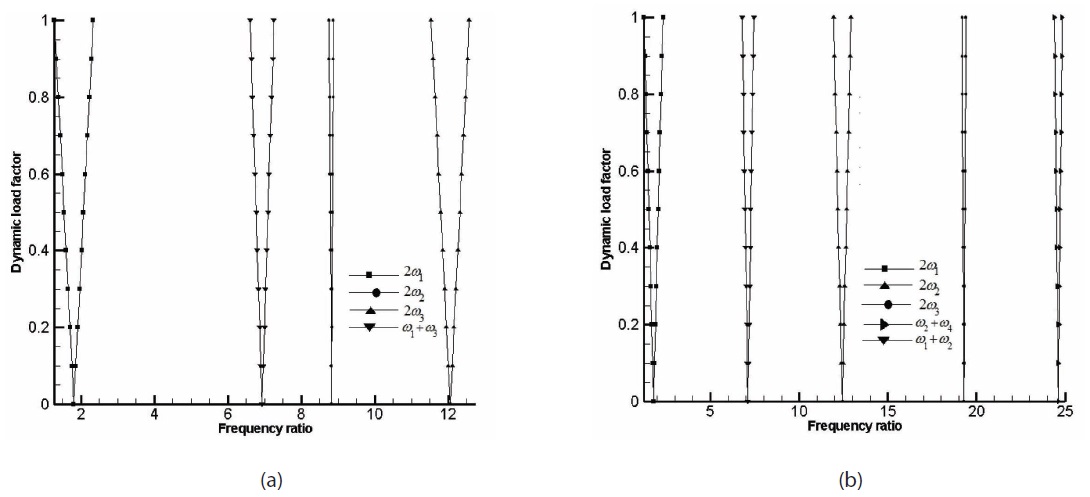
Figs. 5(a) and 5(b) show the simple and combination resonance instability regions of a mildly damaged crossply, cantilevered plate like beam under in-plane harmonic load. As expected, the simple resonance instability regions become more prominent as compared to the combination resonance instability zones. It can be noted that combination resonance due to
The simple and combination resonance instability regions of a clamped-simply supported, mildly damaged cross-ply and angle-ply plate like beam under in-plane harmonic load is plotted in Figs. 6(a) and 6(b). The combination resonance instability zones are again less prominent than the simple resonance instability zones
which can be clearly observed. It can also be noted that compared to the cantilevered case the onset is delayed in the frequency axis and the width of the instability zone has become narrow.
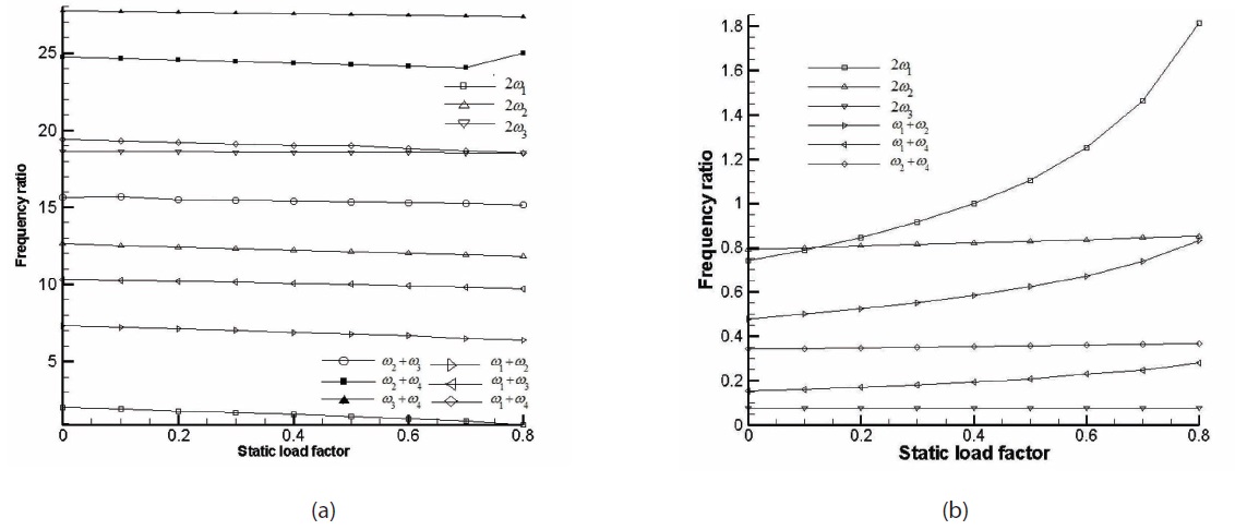
The effect of static load factor (
A static and dynamic instability study of a composite plate like beam having anisotropic damage and subjected to the harmonic axial load is presented in this paper. The results show the effects of damage and its location on the fundamental natural frequency, buckling load, and simple and combination resonance instability behaviour. The observations are summarized into the following points,
? Damage in composite plate like beams show strong orthogonality. It has been observed that damage in the direction of fibre results in steeper deterioration of both natural frequency and buckling characteristics. Damage
in the orthogonal direction to fibre orientation has little influence on the fundamental natural frequency and buckling load characteristics.
? It can be concluded that the locations of damage do influence the frequency and buckling characteristics of the composite plate like beam chosen for the present study. A plate like beam of a certain lay-up is more sensitive to the location of damage. The present study reveals that cross ply lay-up causes noticeable variations in response behaviour with a shift in damage location. It was also observed from the present study that buckling behaviour improves when damage is located near less constrained boundaries.
? It has been observed that as the extension of damage or damage area increases it deteriorates the natural frequency and buckling characteristics irrespective of ply lay-up and ply orientation.
? Damage location contributes more significantly to the parametric resonance instability characteristics than damage intensity. It can be concluded from the present study that parametric instability characteristics can make the structure more vulnerable and drive it to instability much earlier when damage is located towards less constrained boundaries than when located towards well constrained ones, like the clamped end.
? From the present study, the static component of harmonic excitation emerged as a very important parameter that has significant influence in determining the parametric instability zones. An increase in the static component of harmonic excitation is not a welcome development for the structural component as it drives the system into instability zones at much lower excitation frequencies and these new instability zones are wider than those existed for a lesser static load factor value.
? An increase in the damage area advances the onset of simple resonance instability zones further into the frequency ratio axis. The width of these regions increase as the onset is advanced on the frequency ratio axis and vice versa.
The following symbols are used in this paper:
a, b = dimensions of the plate like beam;
[
h = thickness of the plate like beam;
[
[

= normalized stiffness matrix;
[M] = consistent mass matrix;
P(t) = magnitude of harmonic load at time t;
{q} = global degrees of freedom;
[?] = diagonal matrix of eigen values of the free vibration problem;
{ξ} = global degrees of freedom in normalized coordinates;
Г
ψ = fraction of the damaged area, compared with total area, expressed in percentage;
Ω = frequency of harmonic loading;
ω = natural frequency of vibration;

= non-dimensionalized natural frequency of vibration.


![Material properties of each composite layer [Reddy (1984b) and Moorthy et al. (1990)] and dimension of the plate like beam used for present study.](http://oak.go.kr/repository/journal/12071/HGJHC0_2013_v14n1_19_t001.jpg)