The satellite laser ranging (SLR) system is the most precise among the satellite orbit determination systems which measure the distance to the satellite by measuring the returning time interval of laser that is transmitted to the satellite. In 1964, the SLR technique was first used by NASA to determine the orbit of Beacon Explorer-B satellite equipped with a laser reflector, and in those days, the distance measurement had m-level precision. However, the technique is currently very precise having mm-level precision due to the advances in optical and electronic technology, and therefore it is used for many purposes such as the high-precision orbit determination for satellite operation, tracking and observation of cosmic objects, and the research in Earth Sciences (Park et al. 2009). The demand for SLR system is continuously increasing at home and abroad as it provides excellent performance in the fields of satellite operation and Earth Sciences. By 2014, Korea Astronomy and Space Science Institute is successively developing the 40 cm mobile SLR system (ARGO-M) and the stationary SLR system which is equipped with 1 m level optical system (ARGO-F). The ARGO-M has currently been successfully developed and is in test operation.
The tracking target of ARGO-M is the satellite equipped with a laser reflector at an altitude of 300 to 25,000 km, which includes the SLR-dedicated satellite, low earth orbit satellite, and Global Navigation Satellite System satellite. The ARGO-M uses the laser which oscillates the pulse at kHz level, spatial filter, and narrow-band filter to improve the acquisition rate and ensure the precision of observed value for the distance measurement. For the tracking of
Laser GEO dynamic Satellite which is the SLR-dedicated satellite operating at an altitude of about 5,900 km, the precision of distance measurement is 10 mm when the single shot observed value is used, and 5 mm when the normal point observed value which involves the statistical processing of single shot observed value is used (Lim et al. 2010).
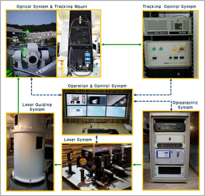
The ARGO-M consists of laser oscillator, transmitting and receiving optical systems, high-speed tracking mount, optoelectronics, and operation and control system (Park et al. 2012). Fig. 1 shows each subsystem that constitutes the ARGO-M. The SLR system is broadly divided into the transmitting and receiving system and the operation system. The transmitting and receiving system includes the optical unit which generates the ultra-short pulse, transmits the pulse to the satellite through the transmitting telescope, and receives and detects the returning photon reflected by the satellite, and the mechanical unit which drives the transmitting and receiving telescopes for tracking the fast-moving satellite (Lim et al. 2011). The operation system performs a general role which controls and operates the entire system for tracking the satellite. The developed ARGO-M system is fully automated and is capable of remote control (Seo 2011). This paper describes the design, manufacture and assembly of parts, and entire optical alignment process for the development of optical system which is the key component of transmission and reception system that constitutes the ARGO-M.
2. CONFIGURATION AND DESIGN OF ARGO-M OPTICAL SYSTEM
For the development of ARGO-M optical system, the optical systems of SLR systems which are currently in operation at the Graz SLR station in Austria and the Herstmonceux SLR station in England were consulted. Both SLR optical systems installed at the Graz and Herstmonceux stations were manufactured by the Contraves Georz Corporation in the United States, and they have the same shape and size. In the case of SLR optical systems used in the above stations, the laser transmission and reception are separated, and the diameters of transmitting telescope and receiving telescope are 100 mm and 500 mm, respectively (Nah et al. 2011). The optical system with the separated transmission and reception has the advantage of minimizing the effect of light scattering, but has the difficulty of precisely aligning the transmitting telescope and receiving telescope. For the ARGO-M optical system, the receiving telescope was designed as 400 mm reflecting optical system, and the transmitting telescope was designed as 100 mm refracting optical system considering the mobility (Lim et al. 2010). In addition to the transmitting and receiving telescopes, the ARGO-M optical system has the detecting optics which transfers the optical signal received at the receiving telescope to the daytime and nighttime cameras and detector (Nah et al. 2011).
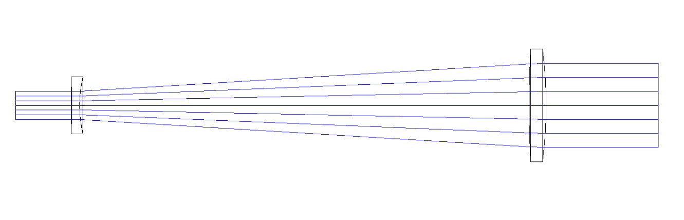
As the transmitting telescope transmits the high-energy laser, it should not have an internal image formation. Therefore, the transmitting telescope was designed as the Galilean refractor which is widely used as a beam expander. Fig. 2 shows the designed transmitting telescope. The transmitting telescope is composed of convex lens and concave lens, and has a magnification of 3x. The transmitting telescope not only expands the laser beam but also adjusts the divergence of transmitting laser beam. The beam divergence is adjusted by changing the position of concave lens at the back. For the transmitting telescope,
the range of beam divergence is 5 ~ 200”. The laser beam generated from laser oscillator enters the transmitting telescope through the coude path of tracking mount. The size of entering beam is currently 25 mm, but it can be adjusted as necessary.
The receiving telescope is a Ritchy-Chretien optical system where both primary mirror and secondary mirror are hyperboloids, and has the F ratio (aperture to focal length ratio) of F/10.3 (diameter 400 mm). Fig. 3 is the optical layout of receiving telescope including the detecting optics. The primary mirror of receiving telescope has the F ratio of 1.5 which is relatively short, and thus the total length of receiving telescope decreases. Accordingly, the detecting optics was placed at the back of primary mirror and at the top of body tube for easy weight balance adjustment. The receiving telescope was designed to have the diffraction-limited performance. However, the design and implementation of detecting optics other than the receiving telescope were carried out with readily available stock lens because the ARGO-M does not require high-quality image.
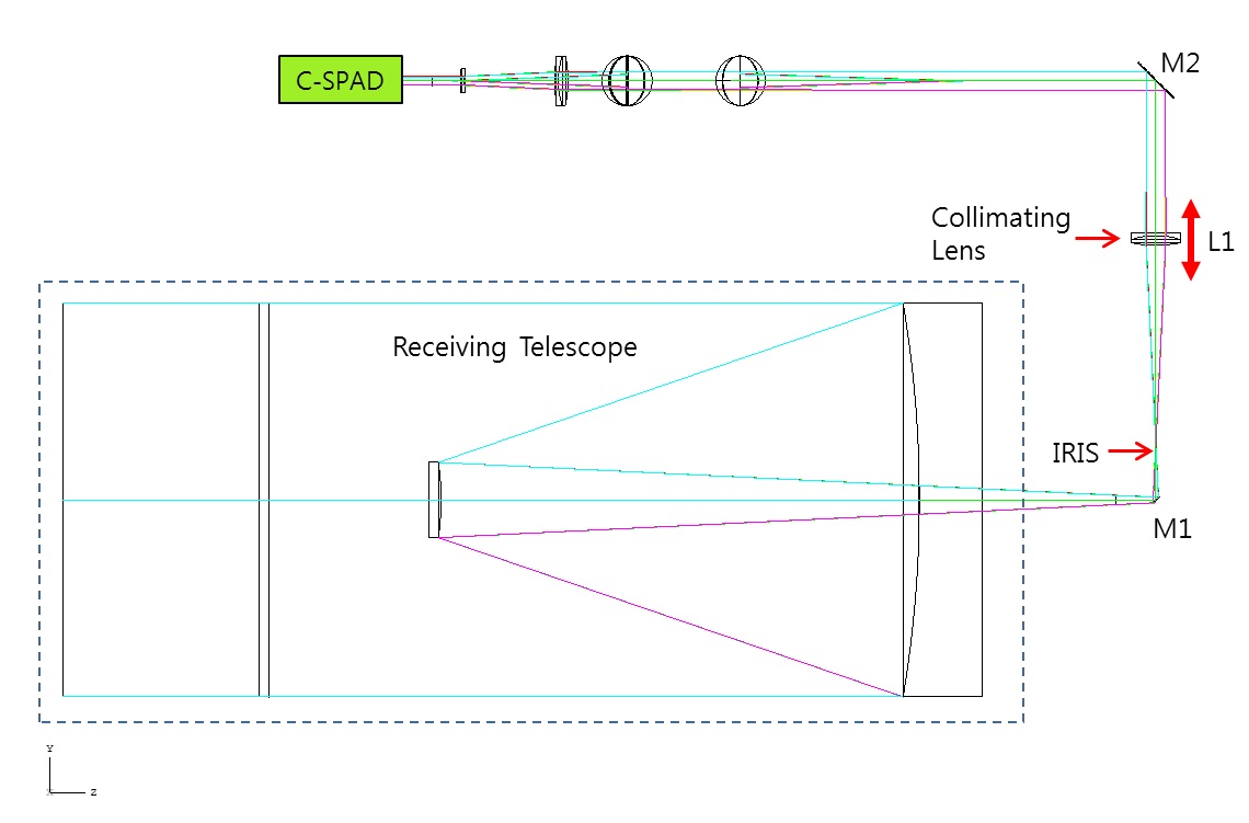
To perform the daytime observation as well as nighttime observation, the ARGO-M requires the functions such as the field of view selection, focusing, optical path change for daytime and nighttime cameras, and obstruction of optical noise using the narrow-band filter. And these functions are performed at the detecting optics located at the back of receiving telescope. Fig. 4 is the optical design drawing
which shows the optical path for the rear part of receiving telescope. In the figure, the configuration of detecting optics starts after the focal plane of receiving telescope (i.e., from the point that the iris is installed).
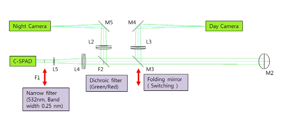
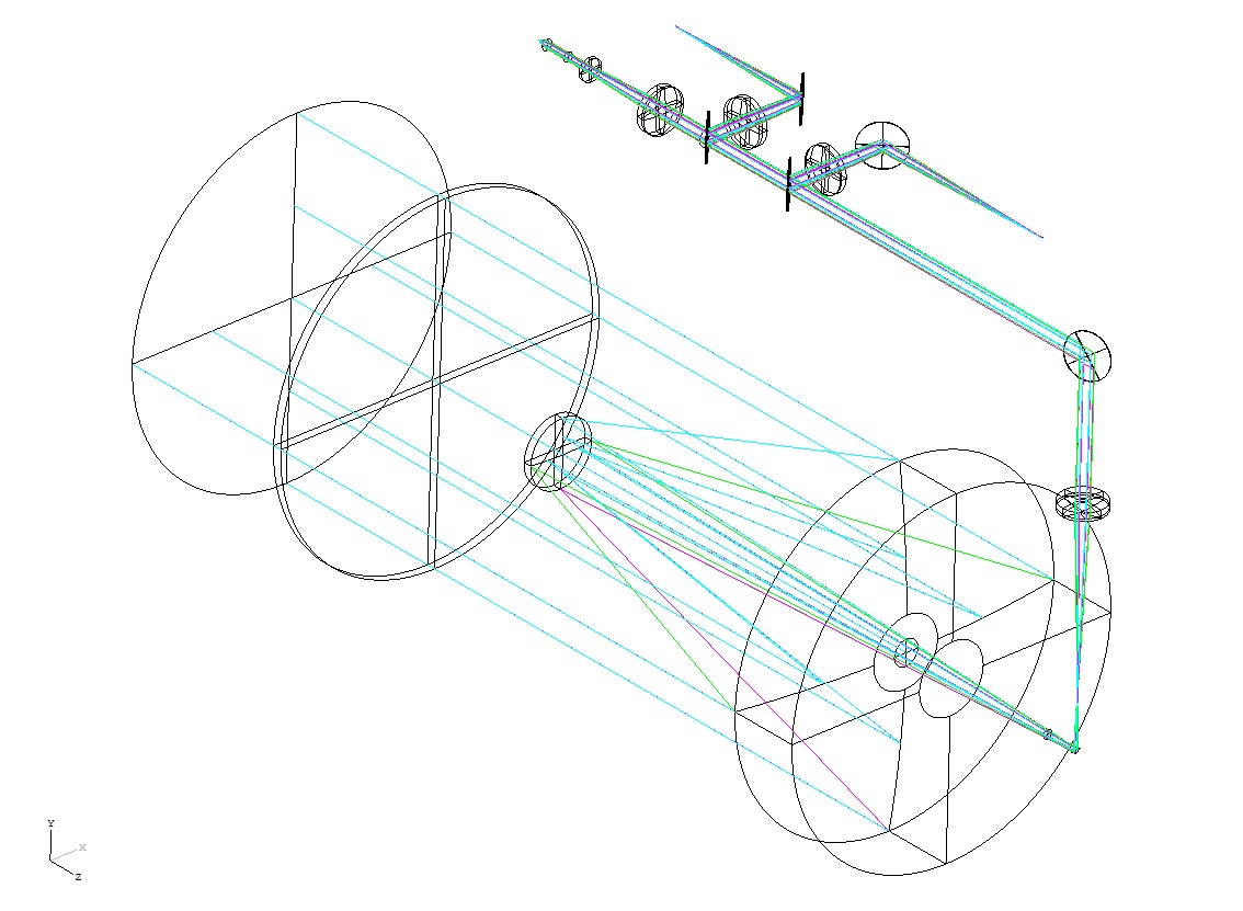
For performing the daytime and nighttime satellite tracking, the ARGO-M operates the daytime and nighttime cameras, respectively. The optical signal collected through the receiving telescope is transferred, through the detecting optics, into the daytime and nighttime cameras and compensated single photon avalanche diode (C-SPAD) which is a distance detector. Fig. 5 shows the configuration of detecting optics and the optical path that the optical signal is transferred in the detecting optics. The optical signal received at the receiving telescope goes through the folding mirror M1 and forms the first image. On the image plane, the iris module which adjusts the field of view of the optical system and obstructs the optical noise is placed. Depending on the size of iris, it is possible to select three kinds of field of views (30”, 150”, and 300”). Passing through the first image plane, the beam is collimated at the focusing lens L1, goes through the folding mirror M2, and is transferred to the detecting optics located at the top of the body tube of receiving telescope. The focusing of daytime and nighttime cameras and C-SPAD is performed by changing the position of lens L1 minutely. In Fig. 5, the optical signal that passed through the folding mirror M2 is sent to the folding mirror M3. The M3 which is installed on the linear stage is positioned inal path for daytime camera observation, and is positioned outsideal path for distance detection and nighttime observation. For daytime observation,al signal which is reflected by the folding mirror M3 goes through the lens L3 and folding mirror M4, and is sent to the daytime camera. For nighttime observation and satellite distance measurement using C-SPAD,al signal which is reflected by the folding mirror M2 is sent to the dichroic filter F2. By the F2,al signal that corresponds to 532 nm is sent to C-SPAD, and the rest of the rays go through the lens L2 and folding mirror M5, and forms the image at the nighttime camera. The optical signal of 532 nm wavelength which is sent to C-SPAD by the dichroic filter F2 passes through the reduction optical system (consists of lenses L4 and L5) and narrow-band filter F1 (532 nm), and is focused by the lens L6 that is built in C-SPAD. Two filters having the bandwidths of 0.25 nm and 1 nm are used as the narrow-band filter, and they can be selected by position change. As mentioned earlier, the stock lens was applied foral design of daytime and nighttime cameras considering the easiness and cost of implementation since the ARGO-M does not require high-quality image. When using the stock lens, it may not exactly match the intended focal length. If there is no lens that matches the intended focal length, the design was conducted utilizing the lens which has a similar focal length. In the configuration applying the stock lens, for daytime camera, the field of view is 304” (5’ 4”) relative to the diagonal direction of camera sensor, and for nighttime camera, the field of view is 313” (5’ 13”). And for C-SPAD, it is 78”. However, the field of view for observation is limited by the iris, and the field of view for the selected iris is the field of view for practical observation.
3. STRUCTURAL ANALYSIS OF PTOMECHANICS
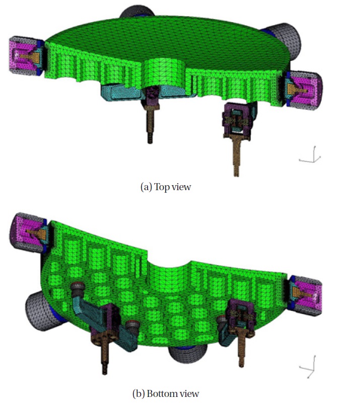
The structural analysis was performed for the entire optical system including the primary mirror because the ARGO-M optical system should be designed and manufactured as a robust structure for high-speed satellite tracking (Nah et al. 2011). The primary mirror was designed as a circular cell shape with the rear side full open form which has a good machinability, and the weight of primary mirror was made to be 12 kg which facilitated 38% weight reduction. Fig. 6 is the finite element model which attached
the designed supporting structure to the light-weight designed primary mirror for the purpose of structural analysis. The finite element model for structural analysis was made based on 1/2 model, and is composed of total 994,821 elements and 1,780,796 nodes. In the rear side of primary mirror, the 6 axial support points are supporting as a Hindle mount form, and the 3 lateral support points and 3 spring support points are supporting the side of primary mirror. The supporting flexure is made of invar. The analysis of optical performance was expressed as the surface error value by converting the deformed optical surface into the Zernike polynomial. When the flexure was not assembled, the result of deformation analysis depending on gravity and temperature indicated that the RMS surface error is 3.5 nm if the gravity acts in the direction of optical axis and the RMS surface error is 10 nm if the gravity acts perpendicular to the optical axis. Therefore, it satisfied the target value of RMS 10 nm. When the flexure was assembled, the result of deformation analysis depending on gravity indicated that the RMS surface error is 9 nm if the gravity acts in the direction of optical axis and the RMS surface error is 12 nm if the gravity acts perpendicular to the optical axis. Table 1 summarizes the result of analysis with respect to the primary mirror equipped with supporting structure when the gravity
[Table 1.] Optomechanical analysis of the flexure-assembled primary mirror.
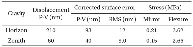
Optomechanical analysis of the flexure-assembled primary mirror.
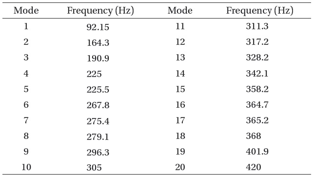
[Table 2.] Natural frequency analysis of ARGO-M optomechanical structure.

Natural frequency analysis of ARGO-M optomechanical structure.
acts in the direction of optical axis and perpendicular to the optical axis. When the supporting structure is attached, the target value is within RMS surface error of 20 nm.
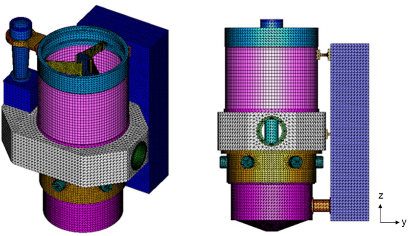
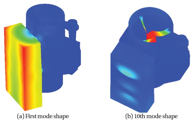
Fig. 7 shows the finite element model of ARGO-M optical system, and Fig. 8 is the mode shape for the result of natural frequency analysis. According to the result of natural frequency analysis for the designed model, the 1st order mode frequency had a high value of 92.15 Hz, and it showed the shape where the detecting optics sways from side to side. In the 10th order mode, the secondary mirror swayed from side to side and the frequency was 305 Hz, which confirms sufficient structural robustness. Table 2 is the result of natural frequency analysis for the ARGO-M optical system model.
4.1 Manufacture of Optical Parts
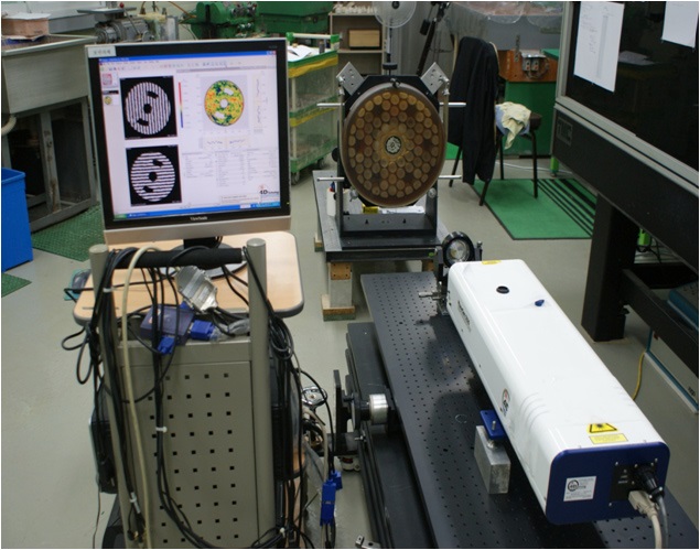
The primary and secondary mirrors which constitute the receiving telescope were manufactured by the Korea Research Institute of Standards and Science, and the manufacture time was about 1 year including the development time for the computer generated hologram (CGH) which is a measuring tool. Fig. 9 shows the optical performance measurement of primary mirror using the
interferometer, and Fig. 10 shows the manufactured primary and secondary mirrors. As stated earlier, the weight reduction was conducted for the primary mirror. After the
[Fig. 10.] Fabricated primary mirror (left) and secondary mirror (right) of the receiving telescope.
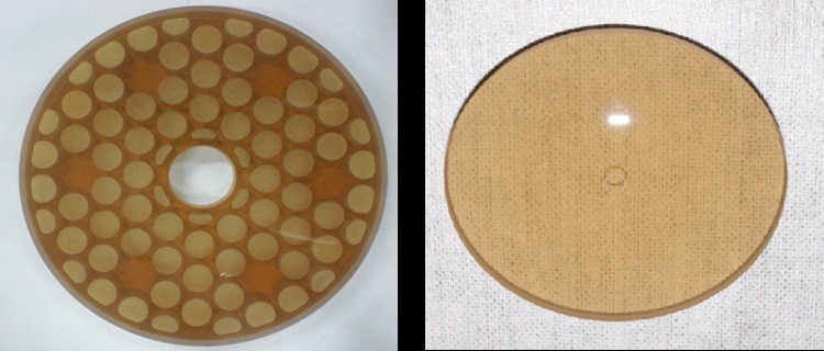
coating, the shape error of primary mirror is 15 nm rms, and the shape error of secondary mirror is 6.3 nm rms.
4.2 Manufacture of Optomechanics
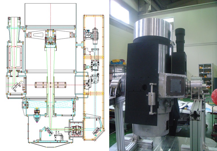
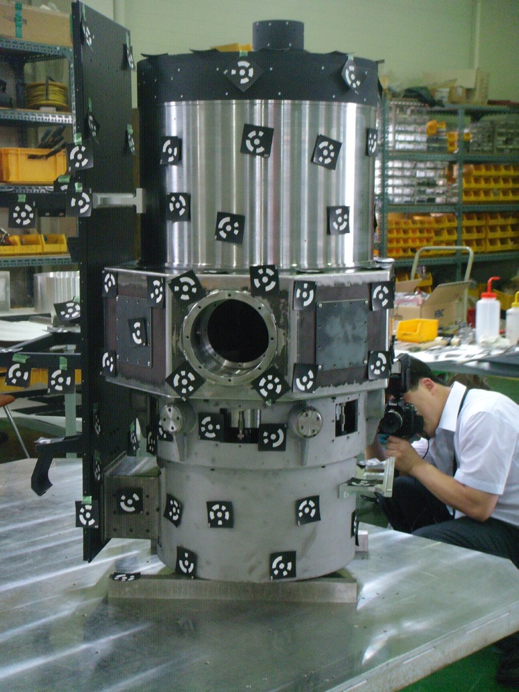
The optomechanical structure of ARGO-M was manufactured by domestic machining company, and the stock products were used for the optical mount parts which constitute the detecting optics for the purpose of configuration flexibility. Fig. 11 shows the 2-dimensional drawing of ARGO-M optomechanics and the manufactured optomechanical structure. And the precision of machine manufacture was checked through the 3-dimensional coordinate measurement prior to painting work. As for the method of 3-dimensional coordinate measurement, it was conducted at a precision of 15 μm with respect to the object with a size of 1.0 × 0.5 × 0.5 m3. The 3-dimensional coordinate measurement was performed in the following order: attaching a measurement mask, taking a picture for measurement, and processing the measurement result (GOM mbH 2013). Fig. 12 shows the 3-dimensional coordinate measurement for the ARGO-M optical system. The precise manufacture of centerpiece is critical for attaching to the tracking mount which is directly connected with the ARGO-M optical system. According to the 3-dimensional measurement for both ends of the centerpiece, the difference between the designed value and measured value was less than 100 μm , which is sufficient precision for mechanically attaching to the tracking mount. The angle between the centerpiece and the body tube of receiving telescope attached to the centerpiece was measured to be 0.010°, which assembly precision of less than 1 arcmin.
4.3 Assembly of Optical System
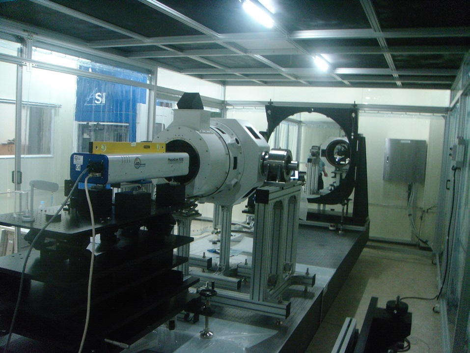
The assembly and alignment of ARGO-M optical system were conducted at a large auto-collimation facility. The autocollimation facility consists of large ultra-high-precision flat mirror (1.1 m), dynamic interferometer (4D PhaseCam 5030), etc. The large ultra-high-precision flat mirror has the precision of PV (Peak to Valley), 1/10 λ (@ 632.8 nm), and the performance of optical systems with the diameter of less than 1 m can be measured in this facility. For the assembly and alignment, the ARGO-M optical system was placed between the flat mirror and dynamic interferometer, and the double pass method was used for the measurement. As for the double pass method, the laser beam from the
interferometer passes through the optical system to be measured, and is retro-reflected by the large flat mirror. And the beam again passes through the optical system and enters the interferometer. Fig. 13 shows the assembly and alignment of ARGO-M optical system at the auto-collimation facility. For the wave front error of receiving telescope measured from the
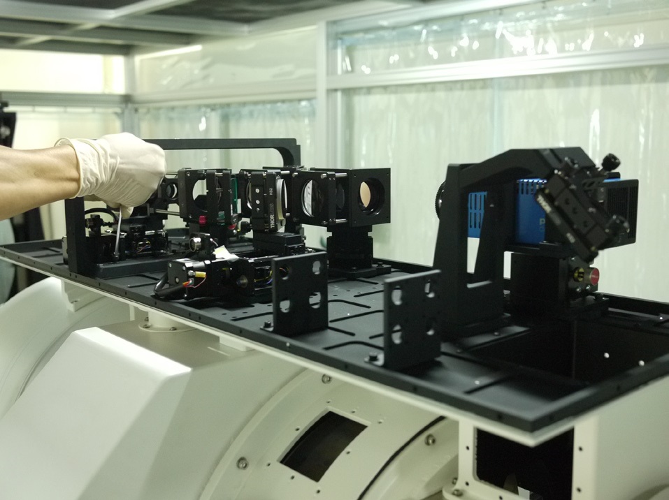
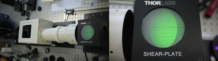
interferometer, the PVq (Q = 99%) was 1.01 λ, and the RMS was 0.1793 λ after the fine adjustment of inclination and position for the primary and secondary mirrors. The PVq is the peak to valley (PV) value which excludes some anomalous measured data, and the Q = 99% indicates that the result is for 99% of the wavefront measurement data excluding the anomalous measured data which is 1%. Fig. 14 shows the installation of detecting optics following the alignment of receiving telescope. The fine alignment of detecting optics was performed through a star observation after attaching the ARGO-M optical system to the tracking mount. Fig. 15 shows the assembled transmitting telescope. The collimation status inspection of laser beam with respect to 532 nm wavelength for the transmitting telescope was conducted using a shearing plate. In the transmitting telescope which consists of convex lens and concave lens, the position that the laser beam is collimated is determined by adjusting the position of concave lens on which the laser beam is incident. And based on this collimation position, the divergence angle of laser beam for the transmitting telescope is adjusted.
5. POINTING ALIGNMENT OF ARGO-M OPTICAL SYSTEM
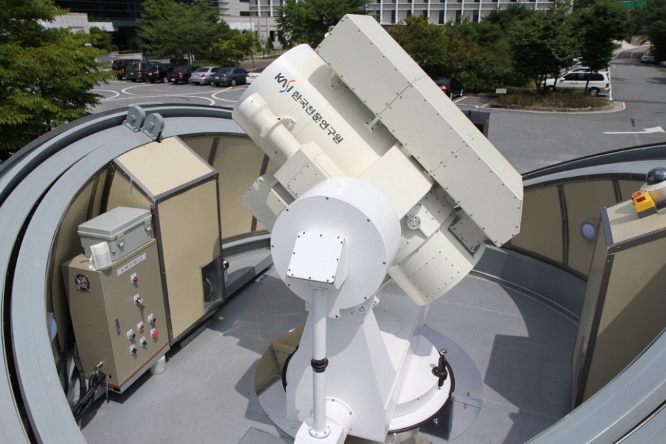
The assembled ARGO-M optical system was installed at the high-speed tracking mount as shown in Fig. 16. The optical alignment was conducted for each optical module during the assembly at the laboratory. However, the optical alignment was carried out again for the receiving telescope and detecting optics as there is a high possibility that the optical alignment is changed after the installation at the tracking mount. For the receiving telescope, the fine optical alignment of primary and secondary mirrors was
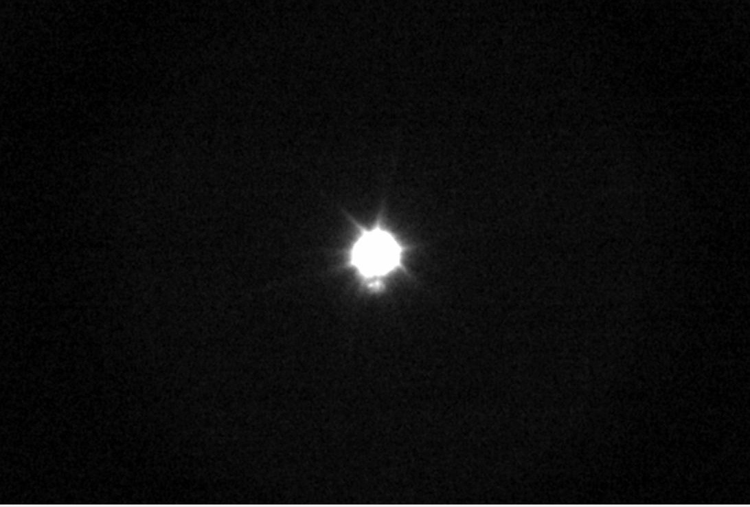
performed using a star testing, and for the detecting optics, the alignment was carried out using the image and signal intensity entering the cameras and C-SPAD while tracking a star. Fig. 17 shows the images of Polaris and companion star obtained from the daytime camera after the alignment of receiving telescope and detecting optics.
In the development of SLR optical system, one of the most difficult processes is to let the transmitting telescope which transmits the laser and the receiving telescope which receives the retro-reflected beam point the same direction. The pointing alignment between the transmitting telescope and receiving telescope was performed in two steps. The approximate pointing alignment was first conducted using a ground target. And for the precise pointing alignment, a laser was transmitted to the sky, and then the pointing directions of transmitting telescope and receiving telescope were aligned while observing the radiant point of laser beam through the image observation (Nah et al. 2012).
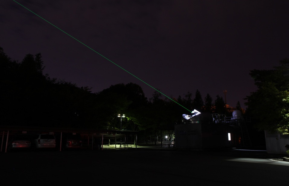
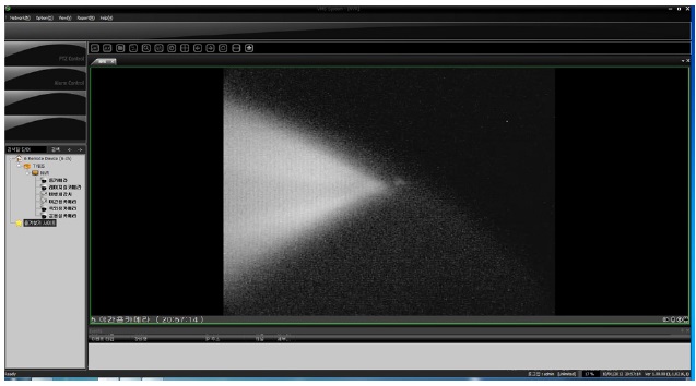
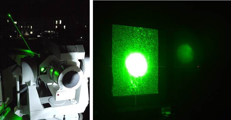
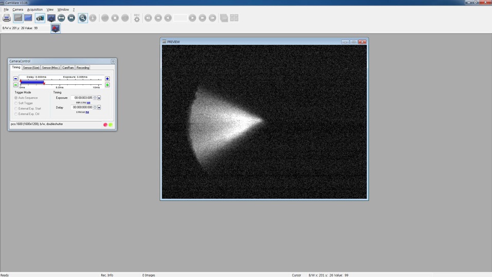
As for the alignment using the ground target, two target plates, that are apart from each other at a spacing which is identical to the spacing between the optical axes of transmitting telescope and receiving telescope, were installed at short distance (more than 100 m). And the pointing directions of two telescopes were aligned by letting the receiving telescope face the center of one plate and letting the transmitting laser beam face the center of the other plate. In Fig. 18, the left figure shows the transmission of laser beam to the short distance target plate installed at the top of a building, and the right figure shows the transmitted laser beam which falls on the alignment target plate. The distance between the ARGO-M optical system and short distance target plate can be easily measured at mm-level precision using a portable laser range finder. The direction control of transmitting laser beam is achieved by adjusting the angle of mirror mount minutely which is located at the back of transmitting telescope. The pointing alignment using the ground target was possible within ±10 arcsec considering that the boundary of laser beam image on the target plate is rather unclear. After the pointing alignment using the ground target, the radiant point can be observed near the center of field of view when observing the radiant point of transmitted laser beam through the camera installed at the detecting optics. The radiant point observation of laser beam was conducted for more precise pointing alignment. Fig. 19 shows the transmission of laser beam to the sky for the radiant point observation of laser beam, and the transmitting telescope and receiving telescope are aligned while observing the radiant point of laser beam in real time. Figs. 20 and 21 are the images of transmitting laser beam observed through the nighttime camera and daytime camera, respectively.
With the advances in optical and electronic technology, the demand for high-performance multi-function optical system is continuously increasing for many purposes such as the high-precision orbit determination for satellite operation, tracking and observation of space objects, and the research in Earth Sciences. One of such optical systems is the ARGO-M which is a mobile SLR system developed by the Korea Astronomy and Space Science Institute with the consideration of mobility and daytime and nighttime applications.
As the ARGO-M performs the satellite tracking in the daytime, the differentiated functions are necessary for the ARGO-M optical system compared to general telescopes, and these functions were included in the detecting optics which is located at the top of the body tube of receiving telescope. The structural robustness is also required since the ARGO-M optical system is attached to the fast-moving tracking mount, and the structural analysis was carried out in this regard. The result of structural analysis indicated that the designed ARGO-M optical system model has a high natural frequency of 92.15 Hz at the 1st order mode, which confirms sufficient structural robustness of the optical system. For the pointing alignment of ARGO-M optical system where the transmission and reception are separated, the transmitting telescope and receiving telescope were aligned within ±10 arcsec using the short distance ground target, and then the pointing directions of the two telescopes were precisely aligned through the radiant point observation of laser beam. The developed ARGO-M is currently in test operation across the entire system, and the performance analysis of satellite tracking with the use of ARGO-M will be discussed in detail on a follow-up paper. The experience acquired through the ARGO-M development will be valuable for the development of 1 m level stationary SLR system which is currently in progress, and expected to be used for the satellite laser communication as well as high-precision orbit determination in the future.