The MPI CyberMotion Simulator provides a unique motion platform, as it features an anthropomorphic robot with a large workspace, combined with an actuated cabin and a linear track for lateral movement. This paper introduces the simulator as a tool for studying human perception, and compares its characteristics to conventional Stewart platforms. Furthermore, an experimental evaluation is presented in which multimodal human control behavior is studied by identifying the visual and vestibular responses of participants in a roll-lateral helicopter hover task. The results show that the simulator motion allows participants to increase tracking performance by changing their control strategy, shifting from reliance on visual error perception to reliance on simulator motion cues. The MPI CyberMotion Simulator has proven to be a state-of-the-art motion simulator for psychophysical research to study humans with various experimental paradigms, ranging from passive perception experiments to active control tasks, such as driving a car or flying a helicopter.
Motion simulators are increasingly used for training purposes, and provide an effective, efficient, and safe environment for practicing maneuvers outside a real vehicle. The characteristics of the vehicles that these simulators represent are simulated to various degrees. For example, the complete cockpit of a commercial aircraft is used in full flight simulators, whereas a generic representation of a typical car is employed in driving schools.
The motion system of training simulators varies depending on the application scenario. Driving simulator schools require a cost-effective solution, and typically provide onset cues and vibrational cues through a motion seat, if motion is provided at all. In contrast, full flight simulators are typically equipped with hexapod motion platforms to reproduce the motion experienced in flight as faithfully as possible, and to provide the pilot with a realistic training environment [1].
All motion simulators have a limited motion range and are never able to completely simulate all of the motion cues experienced in a real vehicle [1,2]. Therefore, motion cueing filters that scale down motion cues considerably and introduce phase shifts are required. In addition, these filters introduce false cues as the simulator needs to be returned to its neutral position. Therefore, the motion experienced by the operator does not reflect the actual state of the vehicle. Despite these limitations, simulator motion is still used in flight training, as it is expected that if a pilot would train without simulator motion, the presence of motion cues in real flight could be disorienting and have a detrimental effect on performance [1]. Similarly, trainees could adapt their behavior, which would result in incorrect control behavior in a real aircraft [3]
The effectiveness of simulator motion has been the subject of many studies on subjects such as the assessment of training and pilot control behavior in closed-loop control tasks. However, the results from these studies provide inconclusive evidence on the effectiveness of simulator motion. In general, the advantages of simulator motion have not been confirmed in transfer-of-training studies for the type of motion offered by Level D full flight simulators [4,5]. Pilots take advantage of motion cues without needing specific training, and the differences in pilot performance and behavior are generally not operationally relevant [6]. On average, simulator motion seems to have a positive effect when combining results from various transfer-of-training studies in a single analysis [7]. This is due to the importance of whole-body motion when flight-naive participants need to learn highly dynamic flight tasks, whereas motion might not be
needed for experts refreshing their maneuvering skills.
In other types of experiments, a positive influence of the availability of simulator motion is found in target-following and disturbance-rejection during closed-loop control tasks [8-11]. In these experiments, simulator motion provides complementary cues to visual cues. Providing participants with simulator motion significantly changes pilot control behavior.
At the Max Planck Institute (MPI) for Biological Cybernetics in Tubingen, Germany, the influence of motion cues on pilot perception and behavior is investigated by performing low-level perception experiments and closedloop control tasks with humans in the loop. Such experimental paradigms can be used to understand and model perception and behavior in the context of driving a car or flying a helicopter. This introduces the MPI CyberMotion Simulator, a state-of-the-art motion platform for performing such experiments. Its capabilities are contrasted with those of conventional Stewart platform simulators, and experimental results in a helicopter hover task are presented.
Simulators are predominantly used for training purposes, although they are also deployed for engineering tasks and research. The majority of simulators that provide motion capabilities with 6 degrees of freedom are based on a parallel (or hexapod) design [12]. Such systems are called Stewart platforms, and are equipped with 6 linear actuators that are capable of carrying large payloads and maintaining high rigidity [13].
An MPI example of a Stewart platform is given in Fig. 1. The characteristics of the simulator are summarized in Table 1. The simulator features electric actuators, like many modern full flight simulators. The actuator stroke is
[Table 1.] Characteristics of the MPI Stewart platform
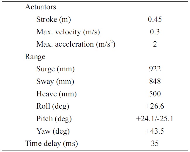
Characteristics of the MPI Stewart platform
limited compared to larger motion platforms, which results in a limited translational range. The rotational degrees of freedom are similar to many Stewart platforms, as they depend more on the actuator layout than on their stroke.
Generally, the fidelity of a simulator is quantified by assessing the degree to which it reproduces the exact state of the simulated vehicle, and technology-centered metrics are used as classification criteria. For example, motion system hardware is characterized by mechanical properties such as bandwidth and time delay. These characteristics can be measured and reported with a systematic approach [14], although simulator manufacturers are reluctant to publish specifications on their motion system characteristics.
Similarly, surprisingly few criteria have been developed to summarize the findings of extensive research on the requirements for motion provided by Stewart platforms [15]. The Sinacori criterion is most widely used. This criterion aims to provide fidelity boundaries for the motion cueing filters that filter the output of the vehicle dynamics model such that the simulator remains within its limits. The criterion shows that the fidelity of the motion cues decreases when the filter gain decreases or the phase shift introduced by the filters increases.
Although a Stewart platform is very suitable for training applications, its parallel motion system can limit the application of the simulator for research into human perception and behavior. A Stewart platform cannot attain unusual attitudes, as its workspace is limited to a volume around the neutral point of the simulator. Therefore, the Max Planck Institute for Biological Cybernetics developed a novel approach to motion simulation that provides a larger simulator workspace.
III. MPI CYBERMOTION SIMULATOR
>
A. Simulator Characteristics
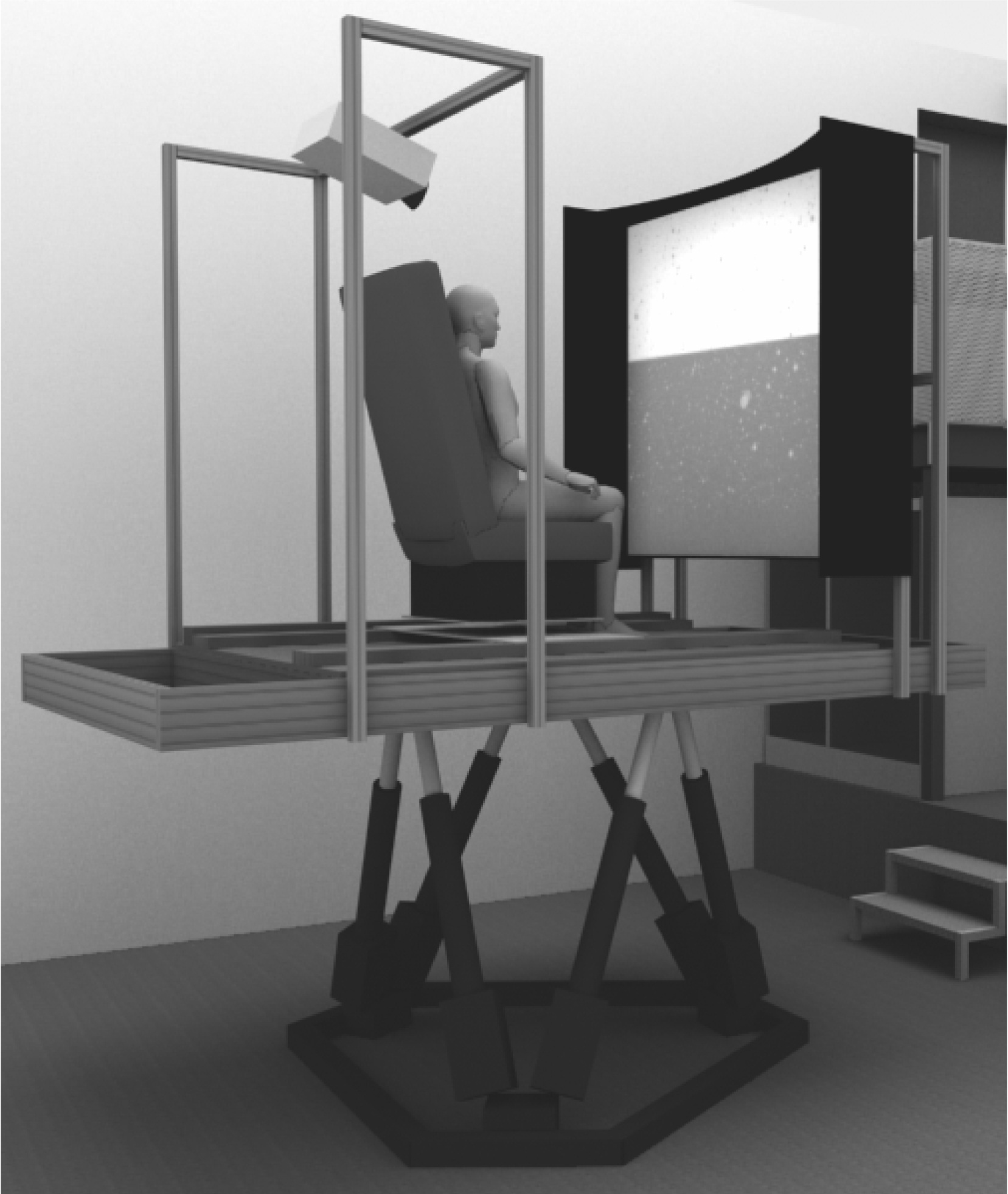
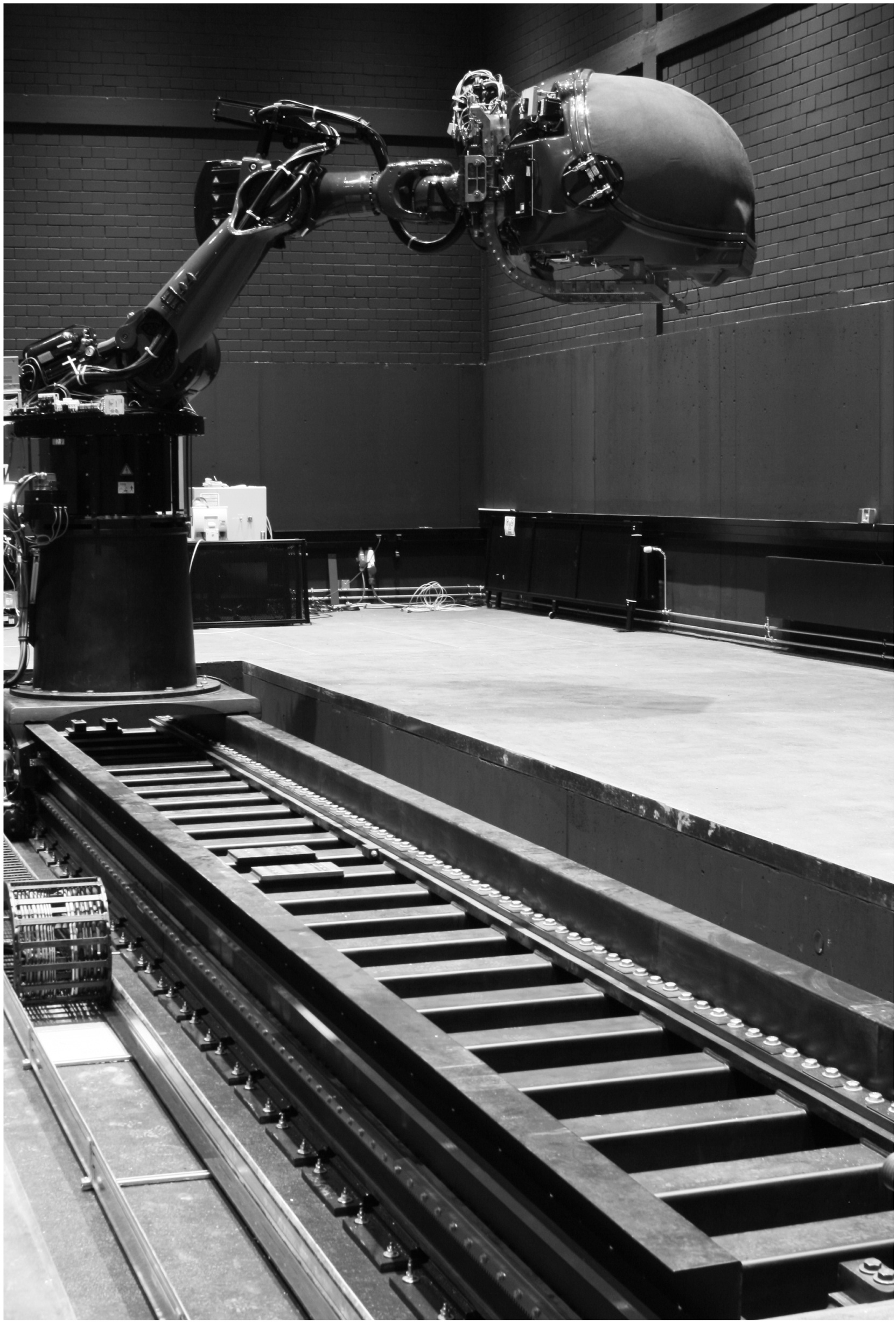
The MPI CyberMotion Simulator, shown in Fig. 2, has
[Table 2.] Characteristics of the MPI CyberMotion Simulator
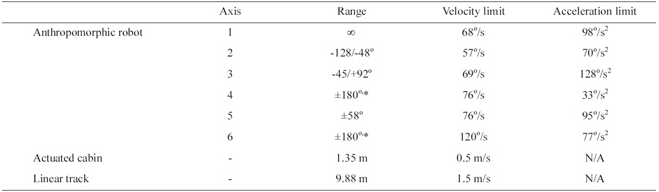
Characteristics of the MPI CyberMotion Simulator
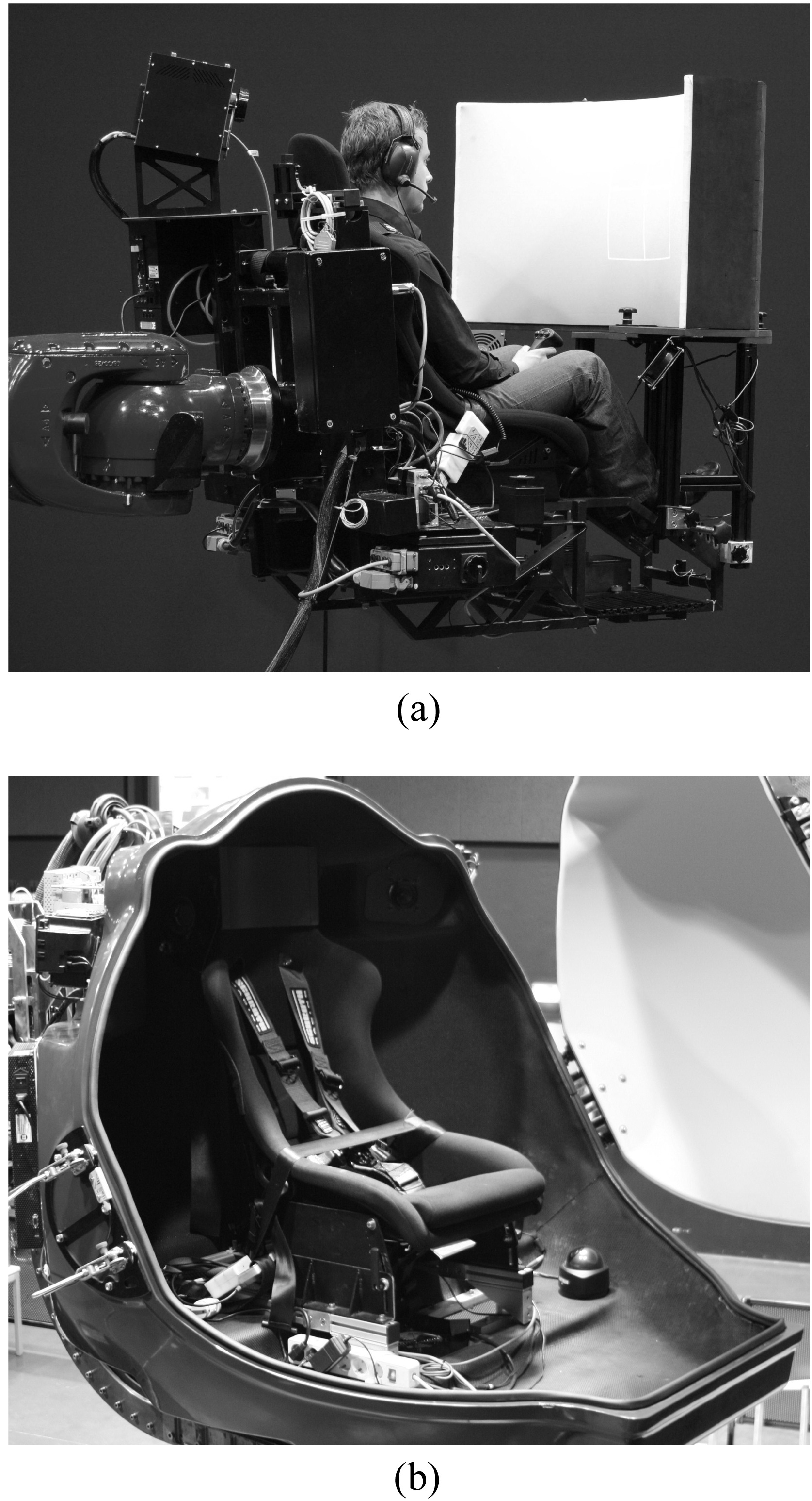
several unique features. The basis of the simulator is formed by an anthropomorphic robot arm based on the Robocoaster from KUKA GmbH, Germany, which has similar degrees of freedom to those of a human arm. The robot arm can be equipped with a seat or an actuated cabin, as shown in Fig. 3. The entire assembly is positioned on a linear track with a range of 9.88 m.
All axes of the MPI CyberMotion Simulator are electrically driven, and their characteristics are given in Table 2. The eight degrees of freedom of the simulator are not
coupled, and therefore, the motion envelope is extended compared to traditional Stewart platforms. Hence, the simulator can be used to move participants into positions that cannot be attained by a Stewart platform. For example, the enclosed cabin can be positioned above the vertically extended robot arm, such that participants can be rotated along the vertical axis indefinitely, and differential thresholds in yaw can be determined. In a different configuration of the simulator, participants can be positioned in any orientation in the enclosed cabin or the seat, even upside-down, to investigate the influence of gravity on perception.
The performance of the anthropomorphic robot that is part of the CyberMotion Simulator has been evaluated by measuring the transport delay of the system and by determining its frequency response [16].
It was found that the transport delay is equal to 41 ms, and that the system shows mechanical resonance at frequencies
depending on the actuator axis. The lowest resonance frequency occurs for the axis at the base of the simulator (axis 1), as it has to drive the largest mass due to the serial configuration of the actuators. Such a configuration can also result in reduced rigidity at the location of the cabin compared to parallel platforms such as a Stewart platform. This results in disadvantages for certain simulator configurations in experimental evaluations where low motion noise is required, such as measurements of motion perception thresholds.
The visualization system of the simulator is different for the seat and the enclosed cabin. In the case of the seat, a curved screen is combined with a single projector and mounted 70 cm in front of the participant as shown in Fig. 3a. The display has an approximate field of view of 90° horizontally 60° vertically. The enclosed cabin has a double-curved projection screen with two projectors (Fig. 3b). The field of view is approximately 140° horizontally and 70° vertically, but the projectors can also be used to display a stereo image with a slightly smaller field of view.
The simulator can be equipped with different input devices, depending on the experimental task. In basic psychophysical experiments, participants typically use button boxes to indicate their response. Furthermore, the enclosed cabin can be equipped with control-loaded devices such as a steering wheel, or a helicopter cyclic stick, collective stick, and pedals.
The MPI CyberMotion Simulator is used for various purposes. First of all, the simulator serves as an experimental platform for basic research into motion perception. For example, measurements of thresholds in response to different motion shapes can enhance our understanding of self-motion perception [17]. Also, the large motion range of the simulator allows for performing path integration experiments in three dimensions, such that assessments can be made as to whether path integration is similar between horizontal and vertical planes [18].
The MPI CyberMotion Simulator is also used to investigate the influence of motion in vehicle control tasks such as driving and helicopter flight. This will lead to a better understanding of human behavior in a simulator environment by modeling human control behavior, or to the enhancement of motion simulation by using models of motion perception within the simulator drive algorithms.
In the next section, an experiment is presented that could only be performed on the CyberMotion Simulator, as it features a large motion workspace. The experiment focuses on the influence of rotational and translational motion cues on control behavior in a helicopter hover task (Fig. 4). The CyberMotion Simulator could provide unscaled and unfiltered cues for translational motion, unlike a general Stewart platform. A cybernetic approach was taken in which human behavior was described with
models based on control theory. As such, human behavior can be measured objectively instead of having to rely on subjective metrics.
IV. EXPERIMENTAL HELICOPTER CONTROL TASK
The research in this section is based on the work described in [19].
>
A. Helicopter Control Task with Roll and Lateral Motion
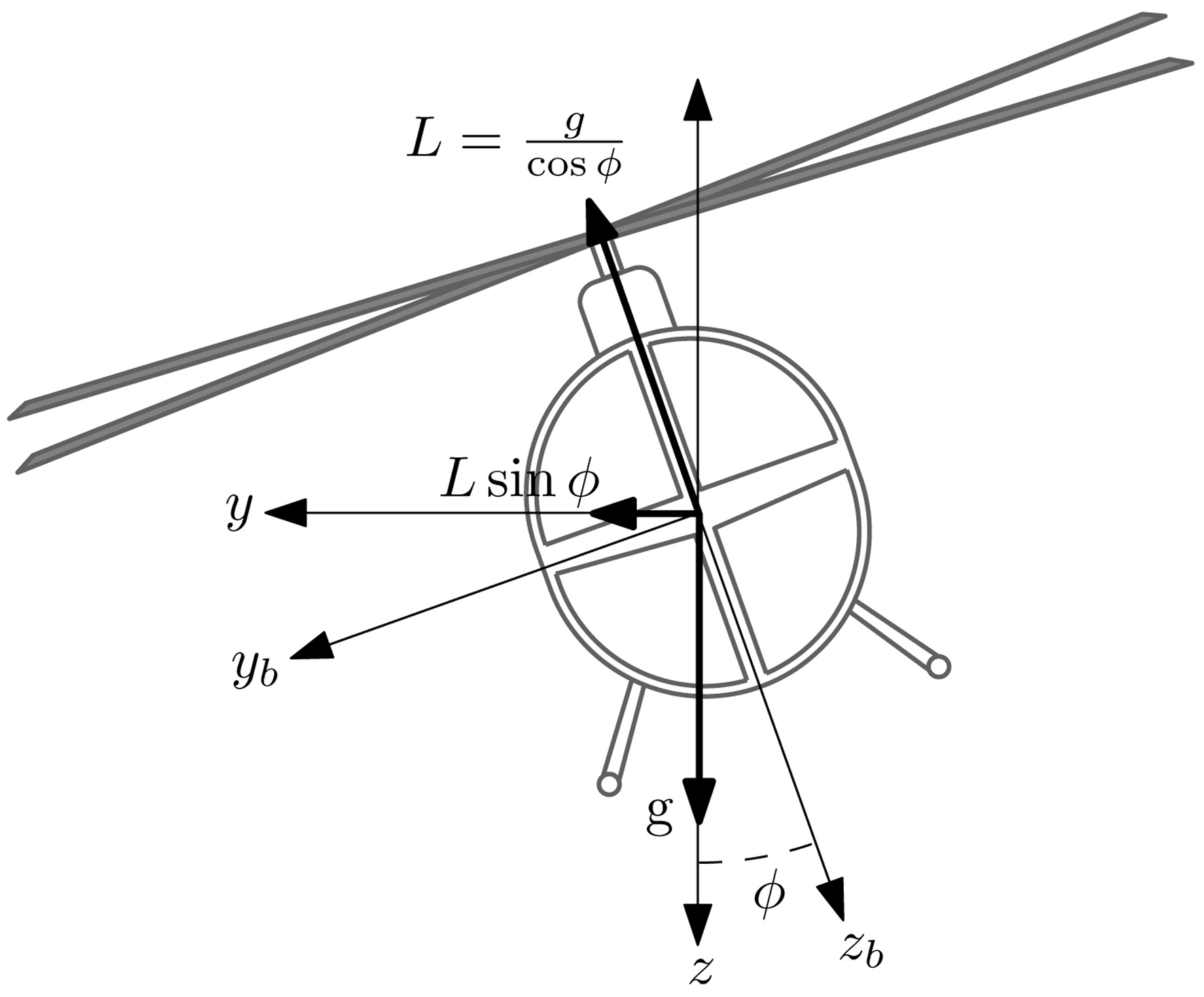
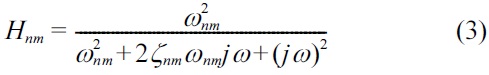
A helicopter hover task with roll and lateral motion can be modeled as a closed-loop manual control task with a pilot in the loop (Fig. 5). In this control task, the pilot generates a control signal
The helicopter flight dynamics are given by the following equations of motion [15]:
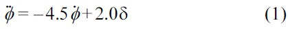

In these equations, the translational motion
>
B. Multimodal Pilot Model Identification
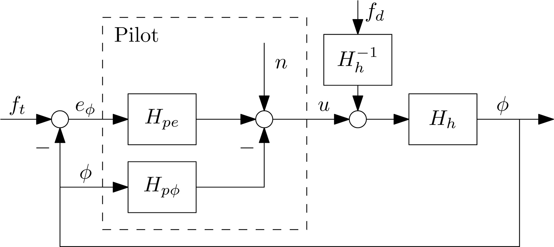
In the control task given in Fig. 5, the pilot controls the helicopter dynamics
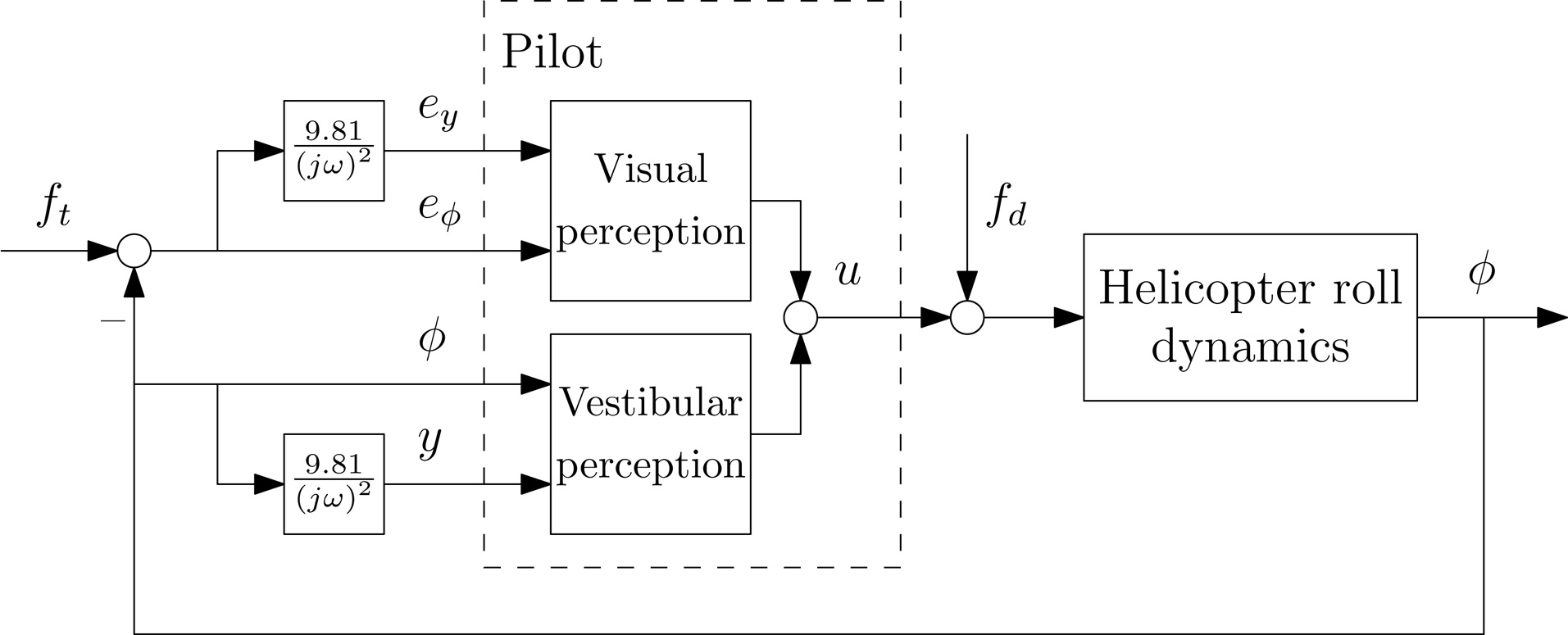
The pilot model considered for this control task is given in Fig. 7, and considers two inputs:
The pilot limitations include the visual time delay
[Table 3.] Experimental conditions
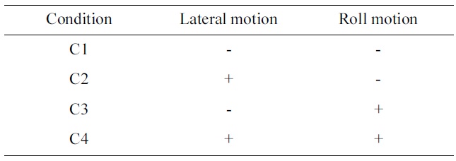
Experimental conditions
where
The open-loop transfer functions of the control loop can be determined for inputs
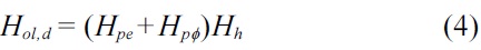
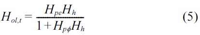
The crossover frequencies
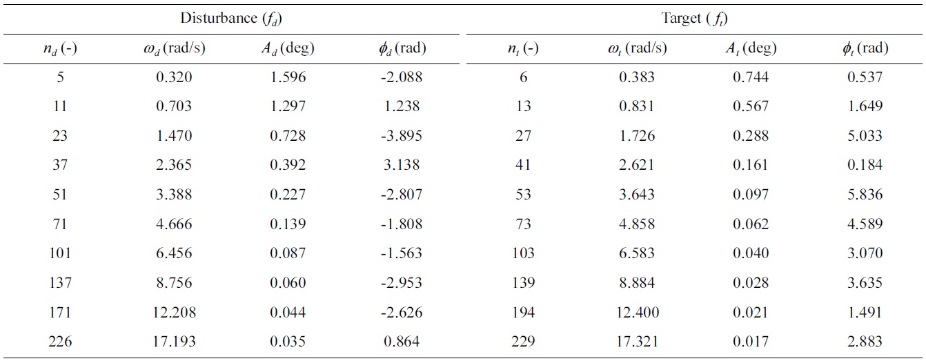
[Table 4.] Forcing function data

Forcing function data
To investigate the influence of simulator motion on pilot performance and control behavior, seven participants took part in an experiment in which the roll and lateral motion of the simulator were manipulated independently (Table 3). During the experiment, five repetitions of each condition were presented randomly. Each trial lasted 110 seconds, of which 98.3 seconds were measurement time. The first 11.7 seconds were not used and allowed the participants to stabilize the helicopter dynamics. Data were logged at 12 ms.
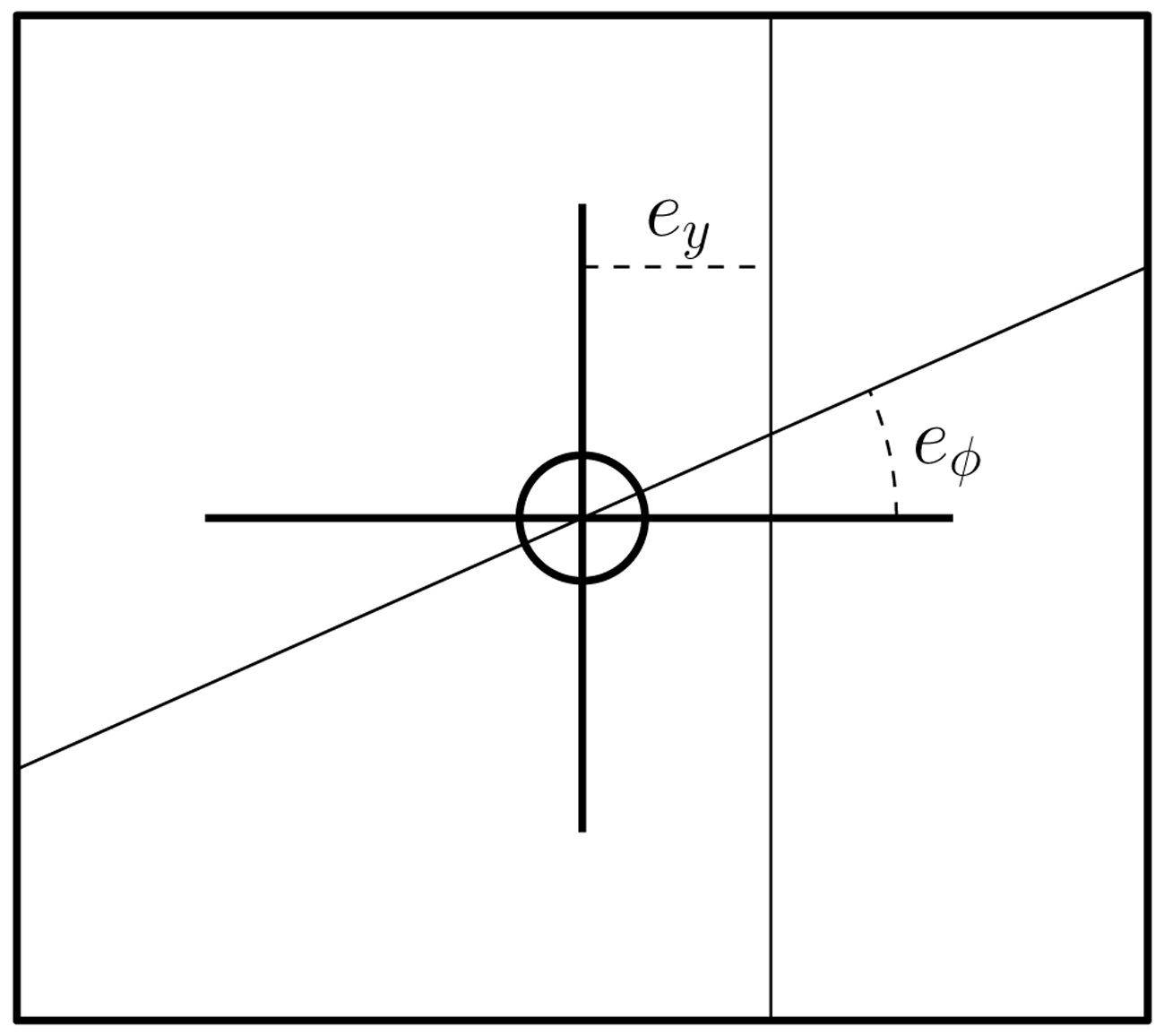
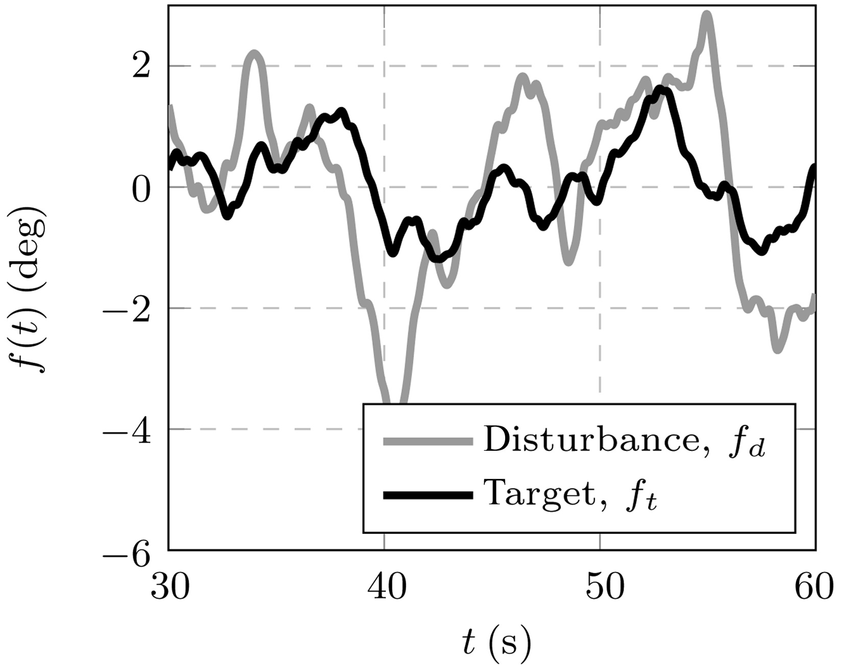
The participants performed a target-following disturbance- rejection control task, which was created by inserting a target forcing function
Where
In this experiment, the MPI CyberMotion Simulator
was used with the seat (Fig. 3a). Roll motion was provided by the axis of the anthropomorphic robot that was closest to the participants, resulting in roll motion around the abdomen. The axis at the base of robot was used to generate lateral motion cues by moving the seat along an arc with a radius of 3.11 m, as the linear track was not yet available. The large motion space of the simulator allowed the experiment to be performed without motion filters. Participants used a cyclic stick with a low stiffness and no breakout force to control the helicopter dynamics. The compensatory display shown in Fig. 6 was projected on the screen in front of the participants. The experiment was conducted in complete darkness to eliminate any visual cues resulting from the static reference frame of the room.
During the experiment, the error signals
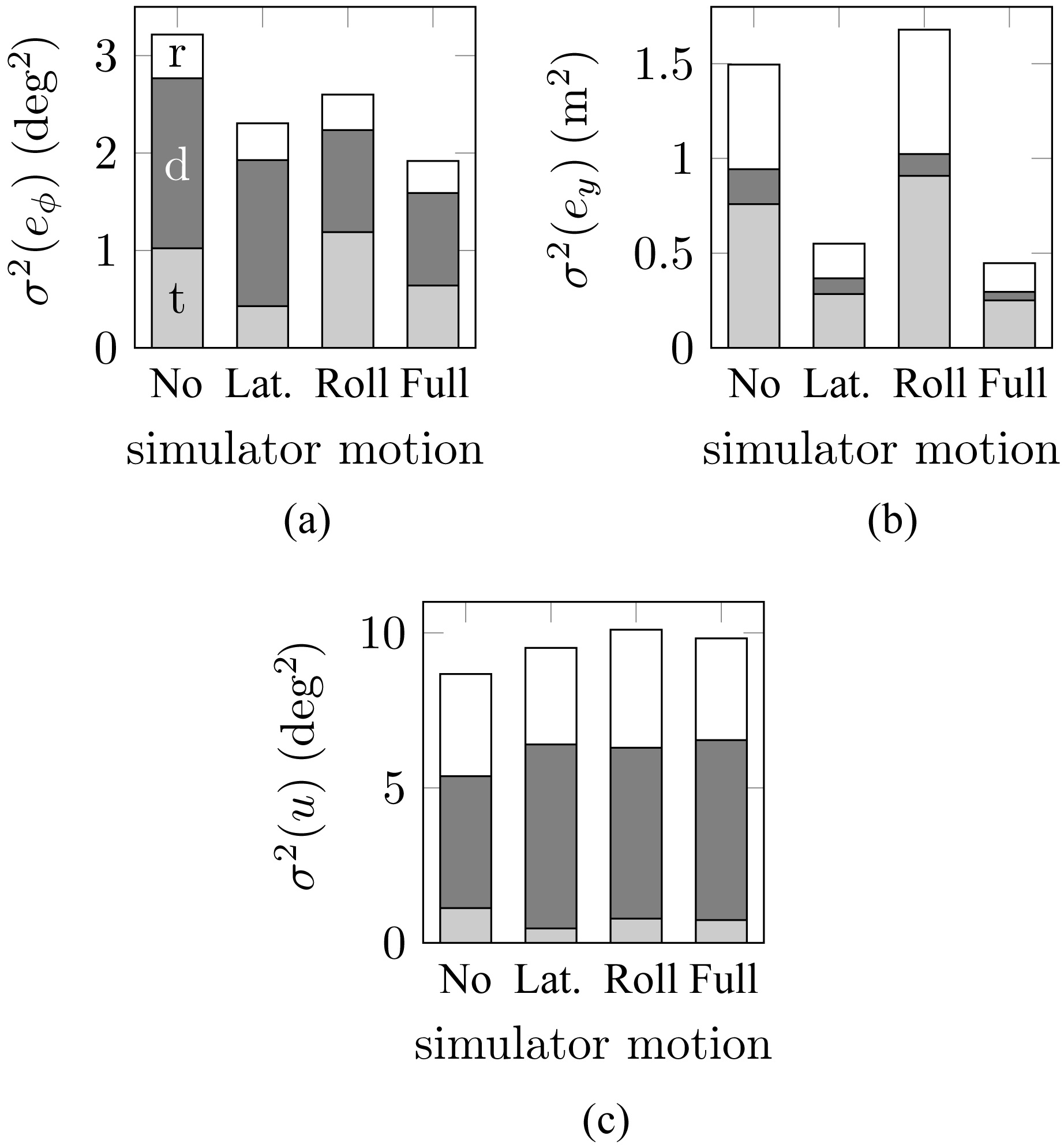
The tracking performance and control activity of participants were evaluated with the variance of the roll error
The control activity of participants was not affected by the availability of motion cues. The variance of the control signal clearly shows that the control task was mainly
a disturbance-rejection task, as this component constituted the largest part of the measured control signal variance.
Pilot control behavior was assessed by determining the parameters of the pilot model given in Fig. 7 by fitting the model to the visual and vestibular response functions
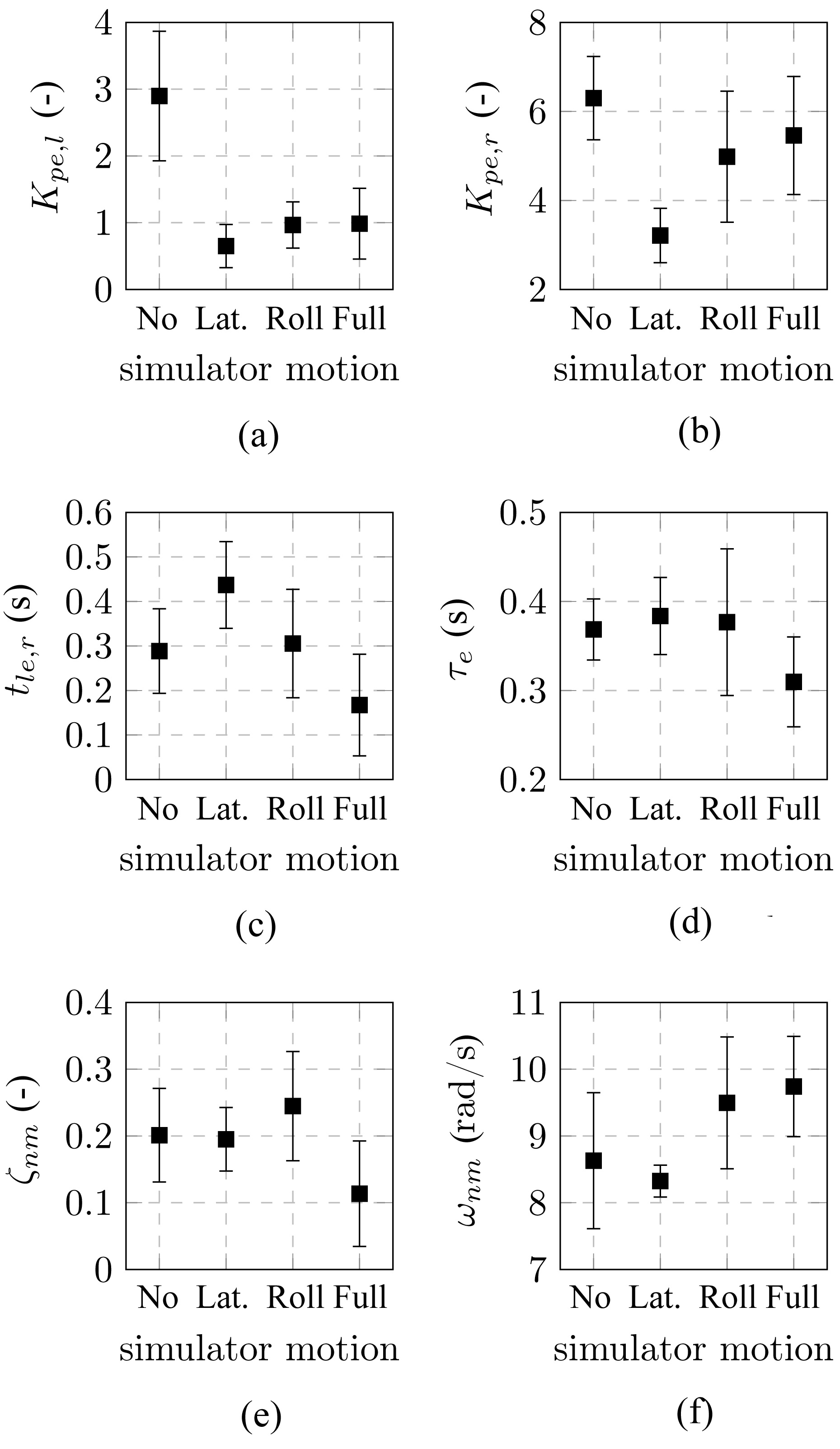
The parameters for the visual perception path
The roll error lead constant was only slightly affected by motion cues. When lateral motion was present, the roll error lead constant was increased, indicating that participants generated lead information concerning the roll angle, i.e., information on roll rate. When both roll and lateral motion cues were present, participants generated less lead,
as is indicated by a decrease in the roll error lead constant.
The visual time delay and the neuromuscular damping frequency were not affected by the motion cues. The neuromuscular frequency was slightly increased when roll motion was present, which was indicative of control over an increased bandwidth.
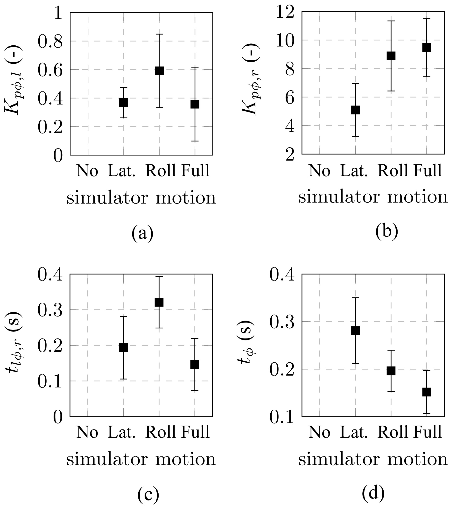
The pilot model parameters for the motion perception path are presented in Fig. 11. Note that these parameters are not defined for the experimental condition without simulator motion. With simulator motion in both degrees of freedom, the motion time delay was decreased further. Tentatively, this indicates the relative importance of simulator motion cues in roll, even though the presence of lateral motion cues provides an additional advantage.
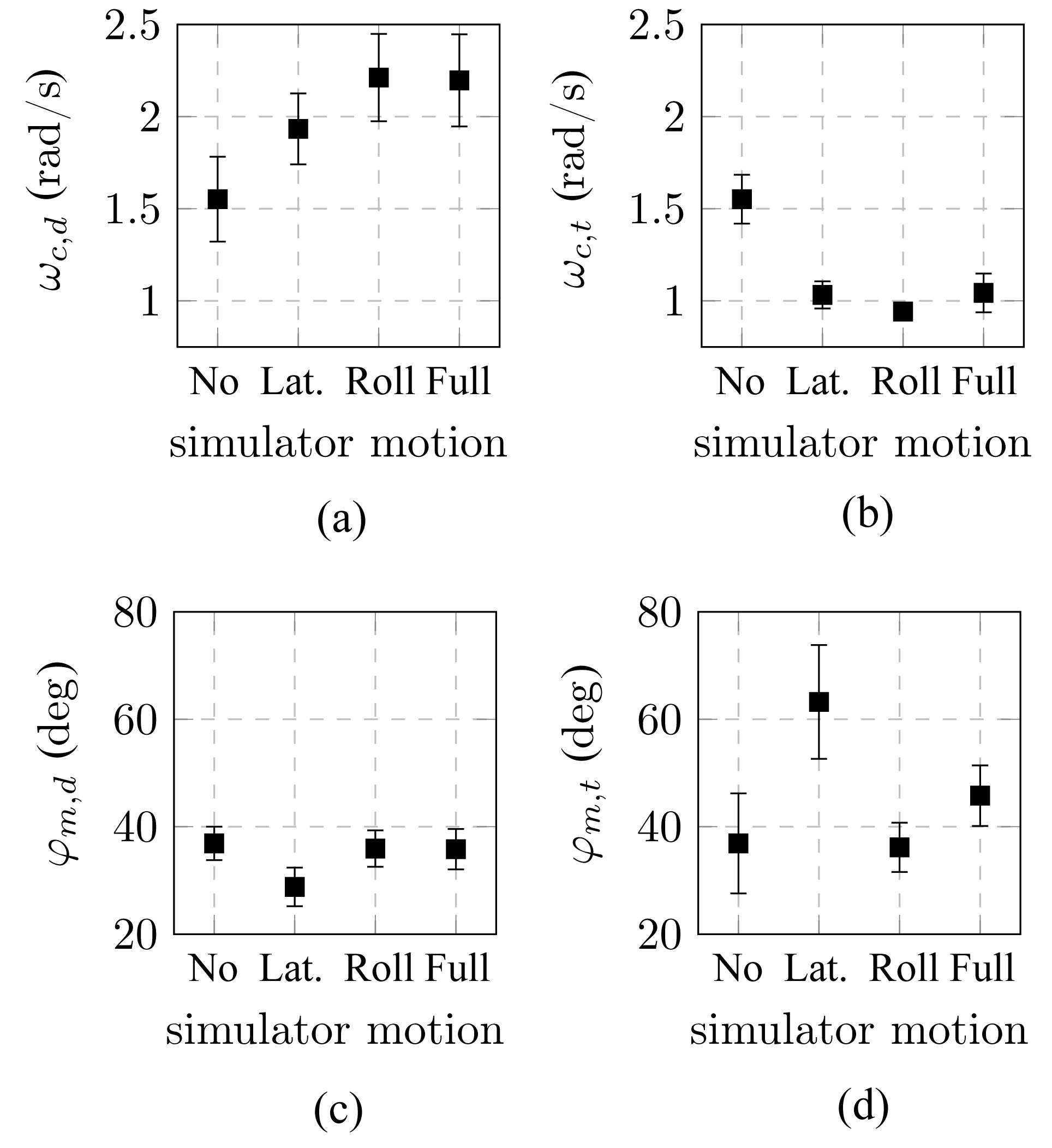
The crossover frequencies and phase margins of the disturbance and target open-loop response functions, presented in Fig. 12, are measures for performance and stability
for attenuation of the disturbance and the target signal. The disturbance crossover frequency increased for conditions with simulator motion, but was larger when roll motion was available. This is an indication that providing motion cues for the inner roll control loop increased the control bandwidth in this task. The disturbance phase margin was only slightly affected in the presence of only lateral motion, which indicates a decrease in the stability of the control loop.
The target crossover frequency was lower when simulator motion was provided to the participants, which could be the result of participants increasing their performance in the disturbance-rejection task, as indicated by an increase in the disturbance crossover frequency. When lateral motion was provided, the target phase margin was increased, indicating higher stability in the control loop.
A motion simulator for any type of vehicular control task introduces restrictions on the type of motion cues that can be provided compared to real world motion. The effect of physical motion on human perception and control behavior is not well understood, and studying such effects in a well-defined and controlled manner remains a challenge. The MPI CyberMotion Simulator provides a unique motion platform with a large workspace that can be used to address this challenge. It can produce large linear motion at the pilot station and attain unusual attitudes compared to conventional hexapod motion base simulators.
The MPI CyberMotion Simulator is used to study human perception in low-level psychophysical experiments measuring factors such as motion perception thresholds, and to assess and model performance, perception and control behavior in closed-loop control tasks. Due to the high workspace volume of the simulator, experiments can, in certain conditions, be designed without the motion filters that are typically used to keep the simulator within its motion envelope.
In this paper, an experiment was presented in which the MPI CyberMotion Simulator was used to study multimodal human control behavior using a cybernetic approach. By identifying the visual and vestibular responses of participants in a roll-lateral helicopter hover task, their behavior was described with models based on control theory. Motion feedback to the participants was changed systematically, by providing no motion, only roll motion, only lateral motion, or a combination of roll and lateral motion. The parameters of the identified pilot models provided insight into adaptations of the participants’ control strategies due to changes in simulator motion feedback.
Participants were able to increase tracking performance when simulator motion was provided. They changed their control strategy to shift from reliance on visual error perception to reliance on simulator motion cues. Participants showed reduced processing times and control over a higher bandwidth when roll motion was present. The change in control strategy was also indicated by an increase in the disturbance crossover frequency with both roll and lateral motion, indicating higher performance in reducing the disturbance error.
Future research on the CyberMotion Simulator will focus on technologies that provide assistance to novice pilots, such as haptics and perspective displays. Furthermore, an ongoing project focuses on building models of human perception and developing simulator motion cueing algorithms based on such models.