The measurement and control of humidity are very important not only for our daily lives but also for the industrial environment. Low humidity might induce health problems such as skin diseases, respiratory diseases, and dry eyes. In addition, people feel poorly and experience discomfort in high humidity. Humidity may affect productivity and the quality of products in industry. Therefore, we need to measure humidity for its regulation.
Humidity can be divided into absolute humidity (AH) and relative humidity (RH). Absolute humidity is the amount of water molecules in a unit air volume. The relative humidity, expressed as a percentage, is the ratio of the partial pressure of water vapor in the air-moisture mixture to the saturated water vapor pressure at the same temperature.
Usually, unless otherwise specifically stated, ‘humidity’ refers to the relative humidity. Humidity can be measured in several ways such as by reading the wet bulb and the dry bulb in a psychrometer, by measuring the dew point, and by measuring the capacitance or resistance of a hygroscopic material.
Even though the dew point method is the most accurate, the instrument is complicate compared to other methods, and it takes time in measuring. For a psychrometer, several inconveniences occur in the maintenance and calculation of humidity. Almost all contemporary electrical sensors utilize the changes in resistance or capacitance when a hygroscopic material adsorbs water molecules. However, the time it takes for the hygroscopic material to be in equilibrium with the surrounding air is excessive. Thus, if the humidity changes rapidly before the material reaches equilibrium, it cannot be used. Furthermore, the material changes its characteristic with time for several reasons including contaminants in the air. Therefore, it would be not always possible to measure accurate humidity.
The motivation for this study was to find a new method for humidity measurement which is simpler, more reliable, and more durable than existing methods.
All materials are dielectric. Every gas has its own dielectric constant [1], because each gas molecule has its own characteristic electric dipole moment. Because a water molecule has a permanent dipole moment and its value is greater than the induced dipole moments of the molecules constituting dry air [2], the overall dielectric constant of air bearing moisture is expected to be greater than that of dry air. Therefore, the increase in the number of water molecules in air in a unit volume may result in the increase of the dielectric constant.
Since an air capacitor is exposed to air, air molecules are free to move in the region between the plates of the capacitor, and the root-mean-square (rms) speeds of the molecules at ordinary temperature are very fast. Consequently, the time it takes for the air inside of the capacitor to reach an equilibrium state with the air outside is very short compared with the cases of other humidity sensing devices.
Hence, we conclude that the capacitance of an air capacitor should be dependent on the partial pressure of water vapor in air. However, we need a concrete theory showing that the change in capacitance is measurable and it therefore must be verified with an experiment.
This paper includes a discussion on this theory, its experiments, results, and conclusions.
In the theoretical section, we will first derive a relationship between the polarizability of the molecule and the static dielectric constant for a homogeneous non polar gas, and an equation for a mixture of such gases. In addition, the dielectric constant will be expressed in terms of the permanent dipole moment, when the gas mixture contains a polar gas such as water vapor.
The capacitance will be determined experimentally by measuring the impedance with the application of an alternating current (ac). Hence, we will see the condition for the validity of the theoretically derived formula because it is obtained under the static circumstances.
Lastly, we will compare the changes in experimentally measured capacitances with those of theoretically predicted values and discuss the results. We will then briefly mention the method for realizing the humidity sensor as an example.
In order to show the dependence of the capacitance of a parallel- plate capacitor on the amount of water molecules in air, it is necessary to determine how the dielectric constant relies on the amount of water molecules in air. Since the dielectric constant depends on the permanent and induced dipole moments of the material filled in the capacitor, we need to find an equation that relates the dielectric constant with the dipole moments.
Because ordinary dry air consists of nonpolar molecules, in the theoretical calculation we will regard the air as composed of nitrogen and oxygen (which are linear and isotropic), and water molecules.
Let us first derive a relationship between the dielectric constant of a gas and the polarizability of the gas molecule in a static electric field. We assume that the electric field is completely localized in the region between the plates and is uniform. In other words, we will ignore the edge effect of the capacitor. Moreover, suppose the capacitor is filled with nonpolar homogenous molecules. For a homogenous and isotropic dilute gas, the polarization is uniform on a macroscopic scale and the molecular field

which is responsible for polarizing a molecule of the gas can be written as [3]
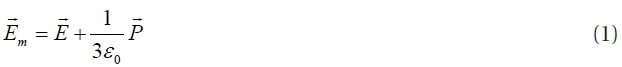
where

is the macroscopic electric field in the gas, and

is the macroscopic polarization of the gas.
If

is the dipole moment of a molecule by the molecular field
, the polarizability

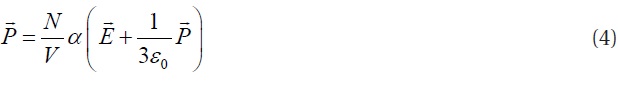
The polarization
can be expressed as

if there are
Consequently, from Eqs. (1), (2), and (3), we have
The relationship among the electric field
, the polarization
, and the electric displacement

in the capacitor is given by [3]

The electric displacement
is a macroscopic field vector satisfying

where K is the dielectric constant of the gas.
Combining Eqs. (5) and (6), we have

Substitution of Eq. (7) into Eq. (4) for the polarizability yields
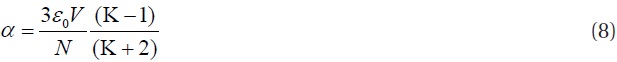
which is known as the Clausius-Mossotti equation.
Since this work is the feasibility study for a humidity sensor using an air capacitor, we will limit the temperature at which the humidity of air is measured in a range from -20℃ to 100℃ and the mixture of air and water molecules will be regarded as an ideal gas.
From the ideal-gas equation
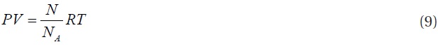
we have
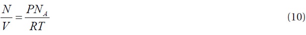
where
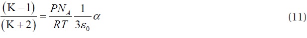
Equation (11) is valid only for a nonpolar mono molecular gas under the assumption that the induced dipole moment of a molecule is determined by the polarizability
where
When we set
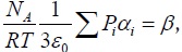
then we have
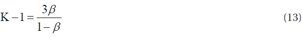
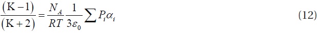
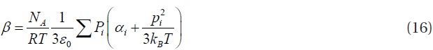
If the gas molecules are polar, they have permanent dipole moments and contribute to increase the polarization. Suppose a gas
Considering the polar nature of a mixture of gases, Eq. (12) becomes
Consequently,
It is not easy to measure accurately the magnitude of charge and potential difference on a capacitor to calculate the capacitance. Here, we name the ratio of charge to potential difference the static capacitance. In this work, we measured the capacitance of an air capacitor using an impedance meter. Namely, the capacitance can be calculated by measuring the current and voltage across the capacitor plates while applying alternating current (ac) with known frequency to the capacitor. Let us call it the dynamic capacitance.
Even in a vacuum, the dynamic capacitance depends on the frequency of an applied ac due to the propagating nature of the electromagnetic wave out of the capacitor. The higher the frequency of the applied ac, the more the electric field permeates out of the capacitor. Therefore, the value of the dielectric constant, and hence, the capacitance, changes. To maintain the electric field inside the capacitor as much possible, we need to decrease the frequency. Because the impedance of a capacitor is 1/2π
As mentioned above, in general, the permittivity
A bound electron in an air or water molecule is not free to move. Therefore, if we regard the motion of the bound electron as a forced oscillation by an electromagnetic wave, we can consider with good approximation the motion of the bound electron as a classical damped simple harmonic oscillator. Since the mass of an electron is so tiny compared with that of the molecule, a distortion of electron distribution mainly occurs at the molecular level by the applied electromagnetic wave. We can then apply Newton’s second law to this electron to obtain
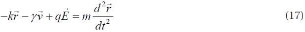
where
is the electric field of the electromagnetic wave,

is the displacement of the electron,

is the velocity of the electron, and
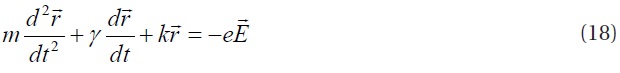
From Eq. (17), we obtain the differential equation of motion
Suppose the applied field
varies harmonically with time, then the time dependent factor is

The dipole moment
of the electron displaced
from its equilibrium position is given by

Consequently, from Eqs. (3), (19), and (20), the polarization is given by
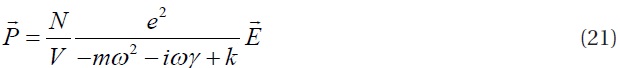
where
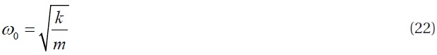
then Eq. (21) can be expressed as
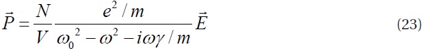
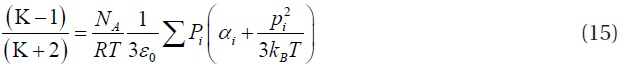
If the frequency of the applied electric field is considerably below the effective resonance frequency, namely
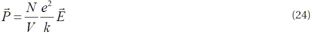
This is the static polarization. 100-kHz is considerably below the effective resonance frequencies of air and water molecules [5]. Therefore, we can use Eq. (15) for the theoretical and experimental feasibility test.
A parallel-plate capacitor was used for our experiment. The capacitor was constructed of aluminum plates with a thickness of 1.5 mm and a size of 400 mm × 430 mm. The plates were separated by 13-mm gaps.
The distance between two plates was made large enough to reduce the effect on the measured capacitance caused by the layers created on the inside surfaces of the capacitor by the adsorbed moisture or air molecules. However, the distance was small enough to observe a change in capacitance due to water molecules and to avoid being over the limit of measurement of the impedance meter.
The surface area of the plates was made to be as large as possible to minimize the error due to the edge effect.
The capacitance was monitored using an LCR impedance meter (GW Instek LCR819). The signal voltage of the impedance meter was 1 V with a frequency of 100 kHz.
We performed the experiment in a closed 3-m × 6-m sized lab. The lab was maintained at a temperature of 20℃. The humidity in the lab was monitored using a commercial hygro-thermometer and controlled with an ultrasonic humidifier.
The humidifier was located at one corner of the lab, and the LCR meter and the capacitor were positioned in the middle of the lab. While measuring the capacitance, all other conditions were kept the same, except the humidity in the lab, to minimize the experimental errors.
In order to equilibrate the air between the capacitor plates with the outside of the capacitor, we increased the relative humidity (RH) in the lab from 16% RH to 36% RH in 2 hours.
Since the purpose of this study was to determine the feasibility of the air capacitor as a humidity sensor, we performed the experiments for two cases, 16% RH and 36% RH, several times and the measured values were averaged for the analysis.
First, the dielectric constants predicted by the theory were compared with the well known experimental data [6] for verification. Here, we used the polarizabilities of N2 and O2 molecules in an SI unit, which were converted from reference [2].
Table 1 shows some calculated values of K under the assumption that the air is composed of 80% N2 and 20% O2, and the experimental values are from reference [6]. The temperature was fixed at 20℃. Although the calculated values do not apply for air, it would be sufficient to show the validity of the equations derived here. If the air is an ideal gas, as the pressure increases, the number of molecules in a unit volume also increases. Therefore, at a fixed temperature, the polarization would be proportional to the pressure. Because
[Table 1.] Values of dielectric constant K at 20℃.
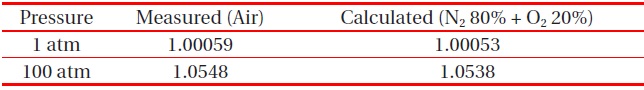
Values of dielectric constant K at 20℃.
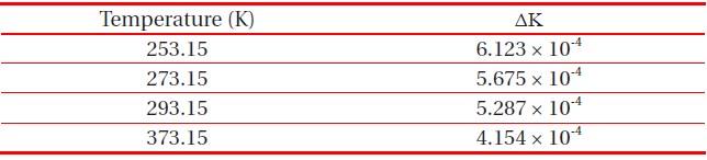
[Table 2.] Calculated ΔK for N2 80% + O2 20% at various temperatures and 1 atm.

Calculated ΔK for N2 80% + O2 20% at various temperatures and 1 atm.
[Table 3.] Calculated ΔK at 20℃ and 1 atm for various RH.
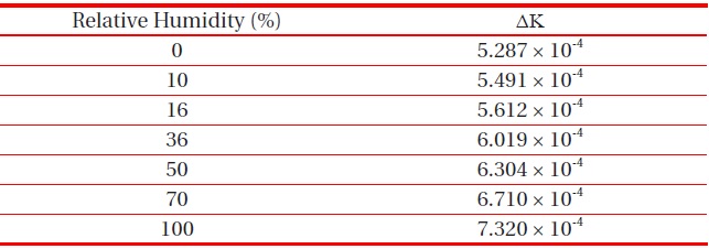
Calculated ΔK at 20℃ and 1 atm for various RH.
For further understanding of the behavior of ΔK, the temperature dependence of ΔK=K-1 was investigated. As the temperature increases at constant pressure, the gas expands, the number of molecules in a unit volume decreases, and the polarization decreases, so that ΔK is expected to decrease. The calculated values of ΔK at 1 atm and at several temperatures for the mixture of N2 and O2 are given in Table 2.
Likewise, we investigated the humidity dependence of ΔK at 20℃ and 1 atm, which can be seen in Table 3. As we expected at the beginning of this work, ΔK increases as the humidity increases.
Suppose C0 is the capacitance of the capacitor in a pure vacuum which is not easy to measure, C is the capacitance with a mixture of air and water vapor, and K is the dielectric constant of the mixture; then, C = KC0 and (C - C0)/C0 is equal to K-1 = ΔK. Therefore, if we have C0, we can compare the theoretically calculated values of ΔK with the experimentally determined values.
If Cs is the capacitance of the capacitor in air with humidity below the measurement limit of the hygro-thermometer, then we have
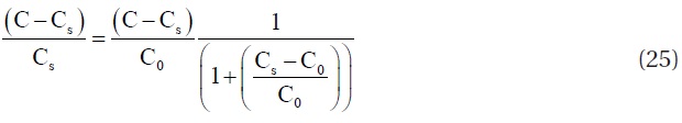
Since the order of magnitude of ΔK is 10-4~10-3 in this study, with a very good approximation, Eq. (25) can be expressed as follows.
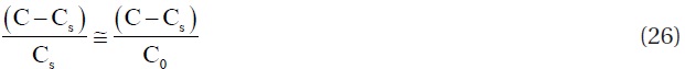
Also, because C > Cs and Cs > C0, we have
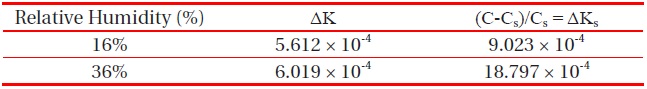
[Table 4.] Values of ΔK and ΔKs at 20℃ for 16% RH and 36% RH.

Values of ΔK and ΔKs at 20℃ for 16% RH and 36% RH.
As mentioned previously, (C - C0)/C0 = ΔK, and it can be calculated theoretically. However, ΔKs=(C - Cs)/Cs can be determined by experiments. Equation (27) implies that the theoretical values of ΔK should be greater than the experimental values of ΔKs. Hence, if experimental results show ΔKs > ΔK, then the air capacitor can definitely be used as a humidity sensing device. The results of ΔKs and ΔK at 20℃ for 16% RH and 36% RH are shown in Table 4, where the values of ΔK are calculated, again assuming the air is composed of 80% N2 and 20% O2, while the values of ΔKs were calculated from the experiments. For the air at 20℃, Cs was 0.13300 nF, C = 0.13312 nF with 16% RH, and C = 0.13325 nF with 36% RH.
As can be seen in Table 4, the changes in ΔKs are greater than the changes in ΔK, as expected in this study. From this research, we verified the notable increase in capacitance with increasing humidity.
All the materials comprising the capacitor would hardly experience any expansion with a change of humidity. Moreover, because the temperature was kept constant during the experiments, the change in capacitance is not due to the thermal expansions of the area and distance of the capacitor. Furthermore, the repeated experiments showed the same results. Consequently, a number of factor(s) are still to be considered in the theory.
Generally, on the surface of a solid in air, a large number of physically adsorbed molecules exist from the air [7]. The capacitor plates we used also should have a thick layer of adsorbed molecules, among which water molecules might exist [7]. Metal has a nature of being highly conductive for thermal energy. Therefore, when a molecule in air with a kinetic energy impinges on the metallic plates, it may lose its kinetic energy by a certain amount in a very short period of time during the collision, and may not have enough energy to return to the air. In other words, impinging molecules on a metallic surface may stick relatively easily to the surface by losing some part of its kinetic energy during the collision.
The density of the adsorbed molecules of a gas is greater than the density of the gas, because the motion of the adsorbed molecule is very feeble compared to that of the molecule in the gas.
Because the water molecule is polar, it may be adsorbed more easily than any other nonpolar molecule on an electric conductor such as a metallic plate.
From the preceding considerations, we could conclude that if the humidity increases, the density of the adsorbed water molecules increases, followed by the overall polarization increase in the capacitor, and finally becomes an increase in capacitance. We need a further study to examine this issue.
The well controlled experimental results clearly show that an air capacitor can be used as a humidity sensing device.
In summary, let us take an example, whereby we can determine the configuration and conditions to make a humidity sensor using an air capacitor.
According to Eq. (26) and our experimental results, we can approximate roughly ΔC ~ ΔK·Cs. Therefore, a large value of Cs is preferable, because it is easy to detect the change in C for that case. Moreover, the capacitance C for a parallel-plate capacitor in air is C =
The possibility of building a humidity sensor using an air capacitor that has a fast response time and longer durability compared with other conventional methods was examined theoretically and verified by experiments.
The humidity sensor in this study can measure not only the relative humidity but also the absolute humidity, because its capacitance changes according to the amount of water molecules in the air.
The changes in capacitance that are measured experimentally are greater than those expected theoretically, which may be due to the adsorbed water molecules on the inner surfaces of the capacitor; this needs further study. In addition, experiments and theoretical considerations on the temperature dependence of the capacitance of an air capacitor may be conducted in a further study.