Microelectromechanical Systems (MEMS) switches [1] designed to work at Radio Frequencies (RF) have been a primary focus of intensive research over the past few years in both academia and industrial organizations. RF MEMS switches have grown at a very fast pace, and have entered into many applications in wireless communication [2] and space sub-systems. RF MEMS switches have replaced the conventional GaAs FET and p-i-n diode switches in RF and microwave systems, because of their negligible power consumption of a few μ-watts, as well as low insertion loss, high isolation, much lower intermodulation distortion, small footprints, low cost, and light weight [3]. Due to the enormous advantages of MEMS switches, they are widely used at RF to millimeter-wave frequencies.
Typically, MEMS switches are fabricated using surface micromachining processes, and have a suspended thin metal membrane called a “bridge,” (which can be fixed-fixed, cantilever, or torsion beams). These bridges allow or block the electronic transmission through mechanical movement of the membrane above the electrode [3]. The membrane is usually made using gold or aluminium material. MEMS switches can be actuated by various methods, such as electrostatic [4-6], electromagnetic [7], piezoelectric [8], and thermal [9] actuation. Due to the near-zero power consumption and linearity, electrostatic actuation is most widely used, in which electrostatic force is generated between the fixed electrode and the movable membrane for switching operation. Several disadvantages include slow switching speeds, high actuation voltage, and hot switching in high-power RF applications [10].
This paper presents an analysis of stress in designed membranes, and the actuation voltage required for different spring constants. After the analyses, effective measures are presented in the discussion section to reduce stress and voltage requirements. The membrane is the most crucial part in MEMS switch designing. Hence, the need of this analysis is mandatory for every switch designed to validate the integrity and reliability of a design. Due to the lack of numerical analysis methods, these challenges can be solved using finite element modeling.
2.1 Fixed-fixed beam type MEMS switches
There are mainly two types of RF MEMS switches: cantilever type and fixed-fixed beam type. In cantilever-type switches, the membrane is fixed at one end and the other end is movable for actuation. While fixed-fixed beams are fixed on both ends, the central portion of the beam is deflected toward the CPW lines to change the state of the switch [6,11].
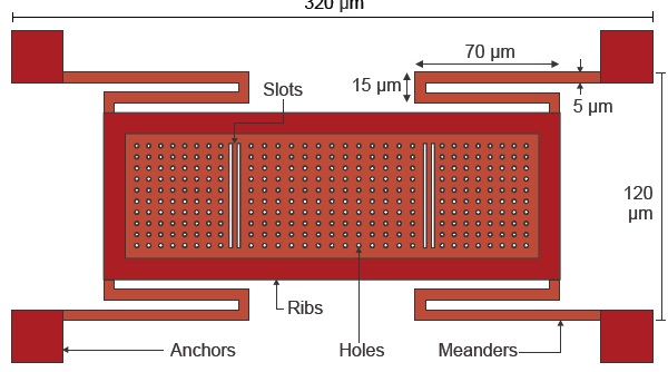
Many different types of membranes have been designed, some of which are single-bar type, while some have meanders. Meanders lower the spring constant of the beam and membrane. However, optimization is required so that the membrane can take advantage of the elastic recovery forces to return to the default suspended position [3].
Different types of meanders are available, but as the complexity of a membrane increases, the stress gradient also increases in meanders [4]. In this case, there can be a chance of breakage after few switching cycles.
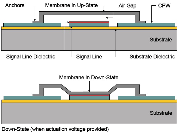
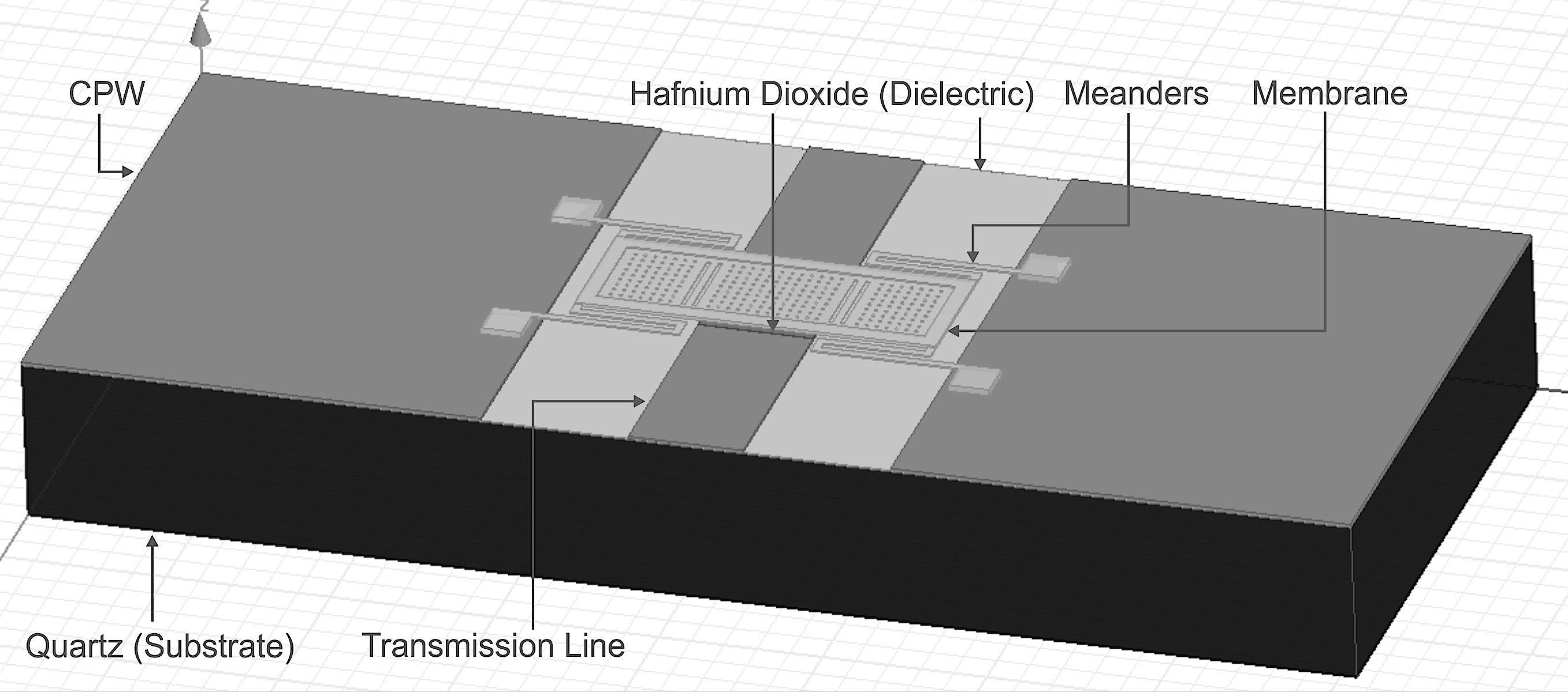
The typical fixed-fixed beam RF MEMS switch operation is shown in Fig. 1. Fixed-fixed beam switches can be series or shunt type. The shunt switches should be connected to the ground of the CPW lines, while series switches should not be connected to the grounds. The membrane is suspended on the CPW lines, while the sides of the membrane have to be fixed on both ends. The typical gap height between a membrane and signal line is 2.5 - 3 μm, depending on the application.
For the analysis, three different types of fixed-fixed beams are used in our previously designed switches, including
A typical RF MEMS switch with a fixed-fixed beam is shown in Fig. 2. The membrane is made on CPW lines.
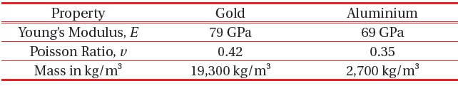
The membranes designed for this analysis cover most of the types of membranes, and some novel membrane designs for our switches. All the membranes are designed first using gold and analyzed, and then the material is changed to aluminum for performance comparison. Table 1 demonstrates the material properties used for membrane design.
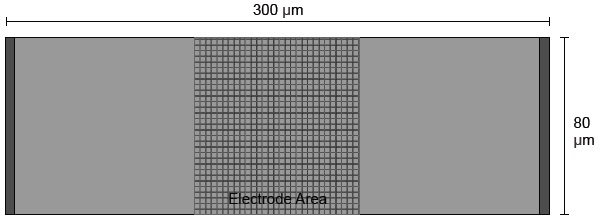
The first type of membrane is the one with no meanders. This membrane is simple and effective for various types of MEMS switches. Two pillars have a fixed height of 3 μm and a beam of L=300 μm and W=80 μm with T=1 μm is mounted on the pillars, such that the gap remains at 3 μm with the signal line. The specifications of membranes
The specific dimensions of membranes
2.4.1 Actuation mechanics and power handling capabilities
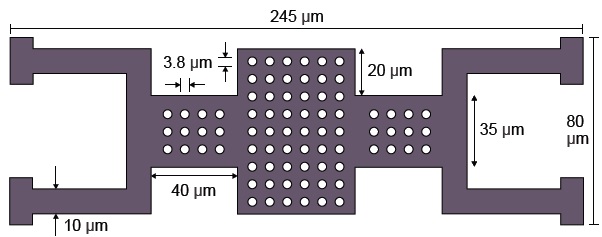
Due to the approach used to design these membranes, the load on a membrane is concentrated in the center, and meanders are used to lower the overall spring constant
[Table 1.] Material specifications.

Material specifications.
[Table 2.] Membrane specifications.
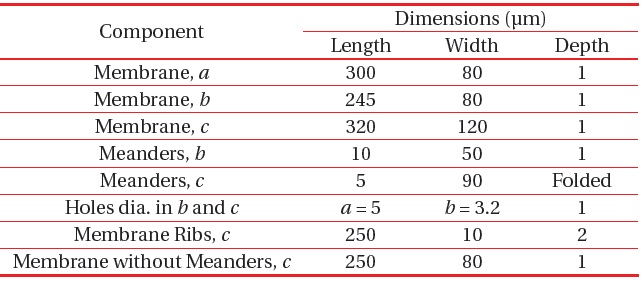
Membrane specifications.
The actuation voltage
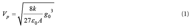
where
The analytical value of the actuation voltages are 25 V for membrane
The power handling capability is augmented in comparison to various designs due to the use of a single electrode. The switch relies on the elastic recovery force of meanders instead of the force of a membrane to pull it upwards, because the membrane is stiff around the edges.
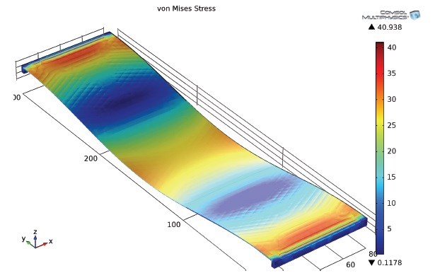
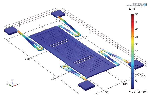
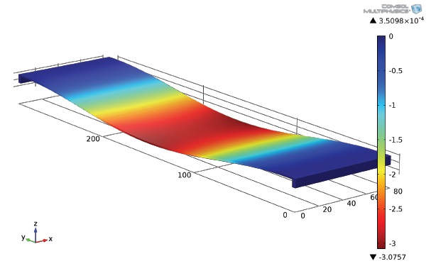
The von Mises Stress is analyzed to check the deflection of a membrane due to stress for a desired height. The membranes made using gold are designed and analyzed for stress simultaneously, and the material is changed to aluminium to analyze the difference. Figure 6 shows the displacement of membrane
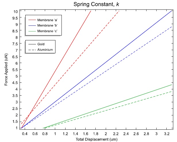
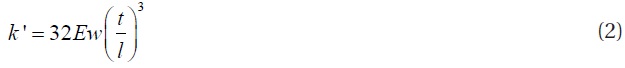
The spring constant,
per unit meter under applied force. The plot is obtained by setting a parametric sweep of applied force. Figure 9 shows the spring constant plot for all membranes made of gold and aluminium. The plotted values are quite close to the analytical calculations. The spring constant is given in (N/m). The spring constant for membranes without meanders with a distributed load can be calculated as [3]:
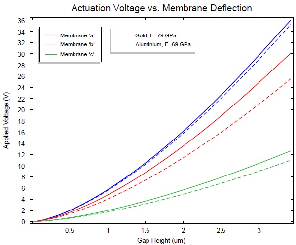
The pull-in voltage or the electrostatic actuation voltage required to pull the membrane down to change the state of a switch can be calculated by eq. (1). The pull-in voltage is plotted vs. gap between the membrane and the signal line is shown in Fig. 10. The graph is plotted for the sweep of the spring constant
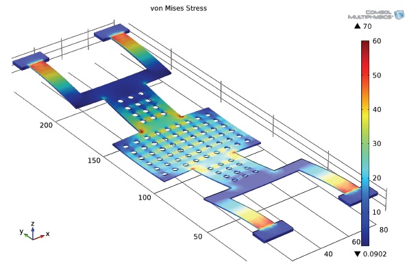
From the results, it is clear that there is more stress in the meanders, but the meanders are needed to reduce the spring constant and pull-in voltage requirement. The gold can withstand 100 MPa of stress, and aluminium can withstand 40-50 MPa of stress before destruction. Thus, from the Table 3, it is clear that the membrane
RF MEMS switches are replacing semiconductor switches
[Table 3.] Performance analysis.
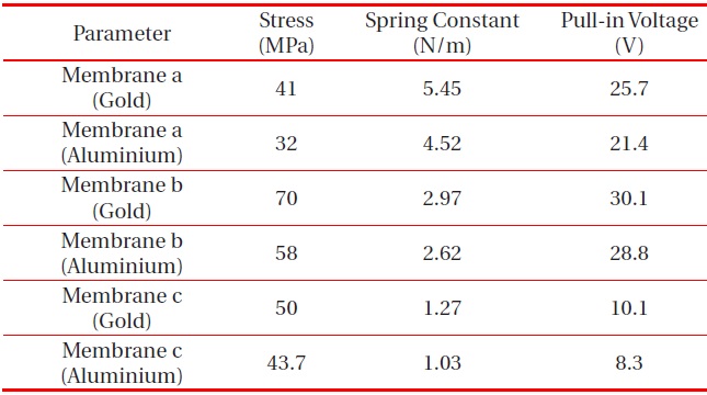
Performance analysis.
due to their tremendous advantages. The membrane is a crucial part of designing an RF MEMS switch. The reliability and performance of a membrane depends on its design. The stress, spring constant, and pull-in voltage were analyzed for different types of membranes made of gold and aluminium. From the results, it is clear that the membrane designed with meanders shows a low spring constant, and thus, low actuation voltage requirements. However, the meanders have to be designed carefully to reduce the stress levels. The von Mises stress has to be analyzed after the design of each part, as it reveals whether the material will withstand the maximum stress levels, or if it leads to destruction.