In this study, we present a more electrochemically enhanced electrode using activated carbon (AC)-sulfur (S) composite materials, which have high current density. The morphological and micro-structure properties were investigated by transmission electron microscopy. Quantity of sulfur was measured by thermogravimetric analysis analysis. The electrochemical behaviors were investigated by cyclic voltammetry. As a trapping carbon structure, AC could provide a porous structure for containing sulfur. We were able to confirm that the AC-S composite electrode had superior electrochemical activity.
Lithium-ion rechargeable batteries (LIBs) have been developed as portable power sources for a wide variety of electronic devices and as power batteries for electric vehicles (EVs) or hybrid electric vehicles (HEVs). The market demand for LIBs has been growing because of their competitive advantages of high energy density and light weight; this will only lead to further improvements. At present, lithium transition metal oxides, especially LiCoO2, are the most successful cathode materials on the consumer market. However, the specific energy ranges of lithium transition metal oxides, which are only specific capacity (100-200 mAhg-1), will not meet the increasing demands of electronic devices. In addition, safety issues regarding lithium metal oxide cathodes are critical because of the cathodes’ intrinsic thermal properties, e.g. fully charged lithium cobalt oxide can release oxygen, which oxidizes the solvent to cause battery thermal runaway. Moreover, cobalt is toxic and expensive. The insufficiencies in current cathode materials limit their applications in future usage, such as in large-scale batteries to power EVs and HEVs. Sulfur (S) has a strong potential to work as a cathode active material in rechargeable lithium batteries [1-4].
Sulfur accepts two electrons per formula unit in electrochemistry and exhibits higher theoretical specific capacity (1675 mAhg-1) and higher theoretical specific energy (2600 mWhg-1 with lithium anode) than any other known cathode active material [5-9]. Furthermore, sulfur is abundant in various minerals, cheap, and environmentally friendly. Therefore, there have been many scientific studies to develop Li-S batteries [10-19]. However, the poor cycle life of Li-S batteries has been a significant obstacle toward their commercialization. During the cycle, fast capacity fading occurs due to a variety of factors, including the dissolution of intermediate lithium polysulfide products (Li2Sx, 4 ≤ x ≤ 8) in the electrolyte, large volumetric expansion of sulfur (~80%) during cycle, and the insulating nature of Li2S. In order to improve the cycle life of Li-S batteries, the dissolution of polysulfides is a key problem. Polysulfides are soluble in the electrolyte and can
diffuse to the lithium anode, resulting in undesired parasitic reactions. The shuttle effect also leads to random precipitation of Li2S2 and Li2S on the positive electrode, which dramatically changes the electrode morphology and results in fast capacity fading. As a result, efficient trapping of polysulfides is highly desired for improving the cycle life of Li-S batteries.
In the study, we introduce the preparation of a composite electrode for Li-S batteries. Activated carbon (AC) is a promising carbon structure. AC is easily produced; it is also abundant in various materials, cheap, and environmentally friendly. The purpose of this study is to present an electrochemically enhanced cathode using AC-S composite materials that have high electrochemical behavior. Another purpose of this study is to look at the electrochemical property by characterizing composite electrodes in organic electrolytes.
2.1. Synthesis of AC-S composite
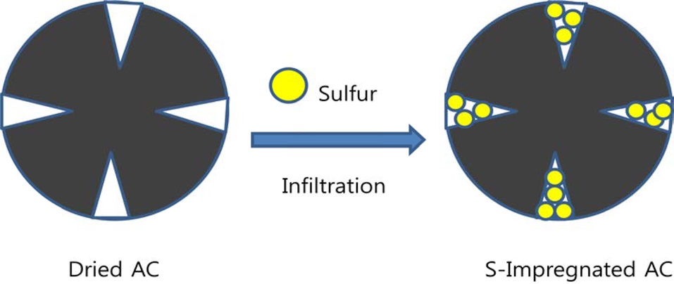
In Fig. 1, AC-S composite was synthesized using the infiltration method. We used MSP-20 material as the source of AC. MSP-20 is known as an active material for super capacitors. At first, 3 g of MSP-20 was heated at 140℃ in air in a muffle furnace and cooled to room temperature. Then, we were able to obtain dried MSP-20 as an elementary material. We prepared a 20 mL vial. We poured 5 mL of carbon disulfide solution into the mixture of 0.5 g of MSP-20 and 0.05 g of sulfur. The mixture was stirred and sonicated. After that, the mixture was heated at 30℃ in a hood in order to dry the solution. We placed the mixture in a muffle furnace and the mixture was heated at 140℃ for drying. Then, we were able to obtain the mixture as an active material for electrochemical measurement.
2.2. Preparation of electrodes
All electrochemical tests were done in a three electrode system. We prepared two types of electrodes. One type of electrode was a glassy carbon electrode (GCE); the other type of electrode was an aluminum foil (Al foil) electrode.
To prepare the GCE, working electrodes were prepared as follows. 5 mg of active material was added to 0.5 mL of distilled water. The mixture was sonicated. After that, 0.1 mL of Nafion was added to the mixture and sonicated. Then, we were able to obtain the mixture as slurry samples. 0.3 μL of the samples were placed on
the GCE and used as a working electrode. Then, the sample-coated electrode was dried at 60℃ in a drying oven. Finally, we were able to obtain the sample-coated GCE for electrochemical measurement.
To prepare the Al foil electrode, working electrodes were prepared as follows. 0.04 g of active material was prepared in the mortar. 0.005 g of Super-P carbon black as a conductive material and 0.005 g of polyvinylidene fluoride were added in a mortar. We poured a small amount of N-Methyl-2-pyrrolidone into the mixture. After that, we prepared slurry samples by mixing. The samples were placed on Al foil and sample-coated Al foil was dried in an oven. Finally, we were able to obtain the samplecoated Al foil electrode for electrochemical measurement.
2.3. Morphological and physical measurements
The morphology and the nanostructures of the samples were investigated using transmission electron microscopy (TEM, JEOL-2010). The quantity of sulfur was measured by thermogravimetric analysis (TGA) analysis (SDT Q600 V8.3 Build 101).
2.4. Electrochemical measurements
We used a platinum rod as a counter electrode; a saturated calomel electrode (SCE) was used as a reference electrode. We prepared the electrolytes as follows. 0.5 M of LiPF6 as a lithium salt was added to dimethylformamide (DMF) solution. The mixture was stirred until the salt was dissolved completely.
The electrochemical measurements were carried out in the prepared electrolytes at room temperature using an Iviumstat (Ivium Technologies, The Netherlands). Cyclic voltammetry (CV) tests were performed for 5 cycles between -2.8 and +1.0 V at 10 mVs-1 of scan rate [15,20].
3.1. AC-S nanocomposite characterization
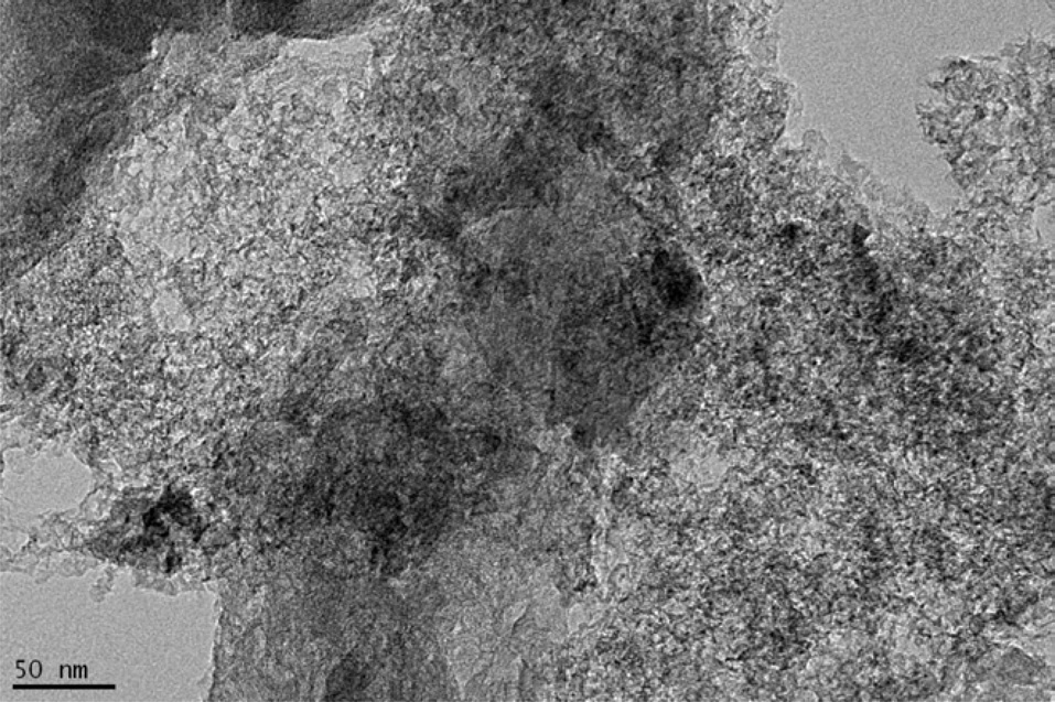
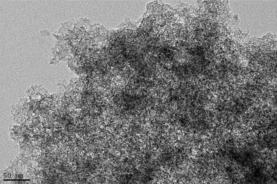
Morphological properties of the composite were analyzed by considering the TEM images. Fig. 2 shows the TEM image of MSP-20. Fig. 3 shows the TEM image of the MSP-20-S01 composite.
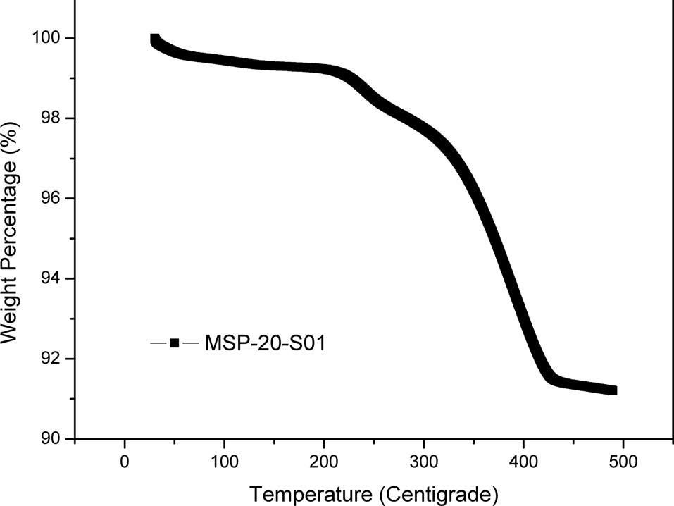
Elemental sulfur was loaded into MSP-20 through liquid phase infiltration by using sulfur solution in carbon disulfide (CS2). The infiltration of sulfur in MSP-20 was carried out through a solution impregnation and drying procedure to attain samples with various loadings using a 10 wt% sulfur solution in CS2. The solvent carbon disulfide was evaporated in a vented hood. After impregnation and drying, samples were annealed at 140℃. The annealing step stripped away the residual CS2. The resulting samples are denoted as MSPO-20-S01, with sulfur loading of 9 wt% determined by TGA in nitrogen. Shown in Fig. 4 is the TGA curve of the MSP-20-S01 composite. At a fixed heating ramp of 10℃/min, the evaporation rate of the sulfur from the MSP-20-S01 composite can be used as indirect evidence to locate the sulfur loaded on the porous carbon.
3.2. Electrochemical characterization
Electrochemical performance characterizations of electrodes were performed using CV. Figs. 5-8 show cyclic voltammograms of the samples during the cycle test. The samples were
analyzed between -2.8 and +1.0 V at 10 mVs-1 of scan rate. We carried out tests for 5 cycles.
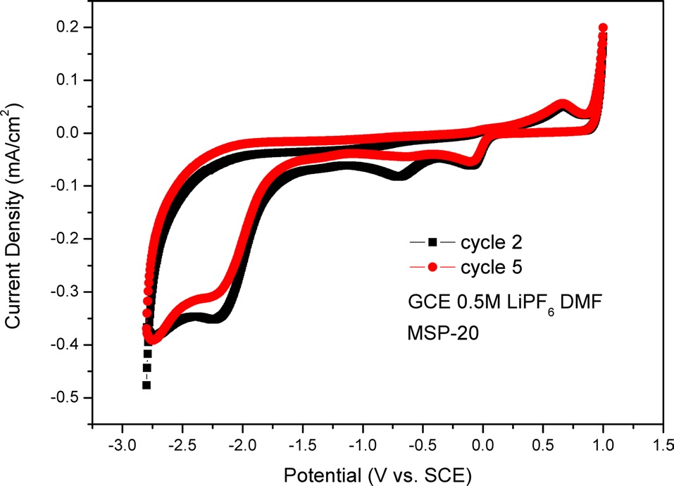
For the data shown in Fig. 5, we used a GCE as an electrode. There was MSP-20 on the GCE as an active material. Fig. 5 shows one oxidation peak and three reduction peaks. The oxidation peak is located at +0.67 V and the reduction peaks are located at -2.21 V, -0.69 V, and -0.09 V. In Fig. 5, in the cathodic process (i.e., the backward scan), the peak current density of cycle 2 is lower than that of cycle 5. This means that electroactivity decreases during the cycle test.
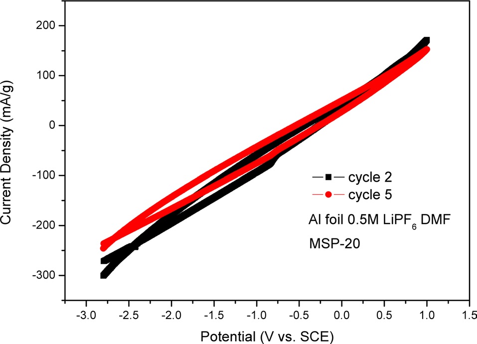
In Fig. 6, we used Al foil as an electrode. There was MSP-20 on the Al foil as an active material. Fig. 6 shows one reduction peak. The reduction peak is located at -0.83 V. In Fig. 6, in the cathodic process (i.e., backward scan), the peak current density of cycle 2 can be seen to be lower than that of cycle 5. This means that electroactivity decreases during the cycle test. The CV graph of cycle 5 has a slighter incline than that of cycle 2.
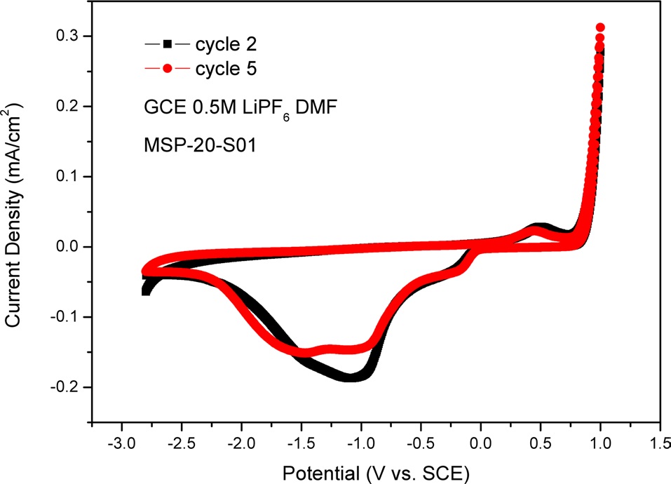
In Fig. 7, we used a GCE as an electrode. There was MSP-20-S01
on the GCE as an active material. Fig. 7 shows one oxidation peak and three reduction peaks. The oxidation peak is located at +0.51 V and the reduction peaks are located at -1.50 V, -1.03 V, and -0.18 V. In Fig. 7, in the cathodic process (i.e., backward scan), the peak current density of cycle 2 can be seen to be lower than that of cycle 5. This means that electroactivity decreases during the cycle test. In the cathodic process (i.e., backward scan), between -1.50 V and -1.03 V, the peak current density of MSP-20-S01 is lower than that of MSP-20. This means that lithium polysulfides can be made between intercalated Li-ion and sulfur in the porous carbon structure.
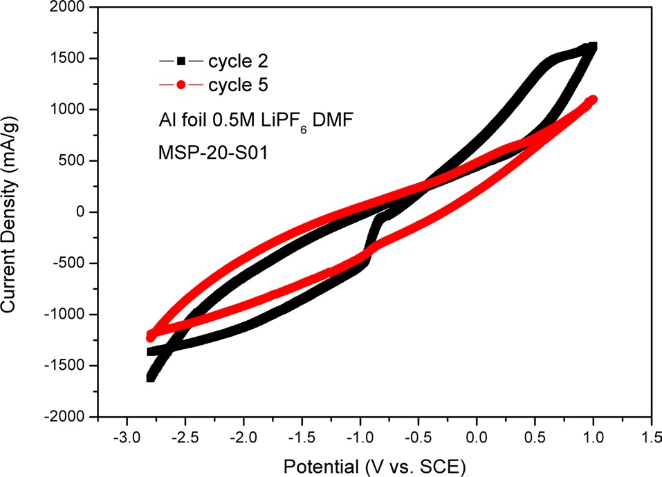
In Fig. 8, we used Al foil as an electrode. There was MSP- 20-S01 on the Al foil as an active material. Fig. 8 shows two oxidation peaks and one reduction peak. The oxidation peaks are located at -0.83 V and +0.64 V and the reduction peak is located at -0.96 V. In Fig. 8, in the cathodic process (i.e., backward scan), we were able to see two oxidation peaks. The two oxidation peaks of cycle 2 disappear during the cycle test, so there are no oxidation peaks in the CV graph of cycle 5. The peak current density of cycle 2 is lower than that of cycle 5. This means that electroactivity decreases during the cycle test. The CV graph of cycle 5 has a slighter incline than that of cycle 2. The important thing here is that the area of MSP-20-S01 is larger than that of MSP-20. This means that lithium polysulfides can be made between intercalated Li-ion and sulfur in the porous carbon structure, so we were able to confirm more electroactivity.
When we compare Fig. 7 with Fig. 8, Fig. 7 shows more curves of peak current density than does Fig. 8. Because GCE was made with graphite, the surface of GCE doesn’t react with Li-ion. So, in detail, Fig. 7 can show lithium polysulfides that can be made between intercalated Li-ion and sulfur in a porous carbon structure. However, in Fig. 8, because MSP-20-S01 was placed on one side of the Al foil, Li-ion can be attached to the other side of the Al foil. So, Fig. 8 shows less lithium polysulfide than does Fig. 7.
In this study, AC-S composite was prepared through an infiltration method using an organic solvent. This simple preparation process can provide a promising route for cost-effective production of processible carbon materials. As a trapping carbon structure, AC can provide a porous structure for containing sulfur. Lithium polysulfides can be made between intercalated Li-ion and sulfur in the porous carbon structure. We were able to confirm that the AC-S composite electrode had current density superior to that of the AC electrode. From the electrochemical characterizations, we were able to confirm that the AC-S composite can be an effective cathode candidate material for Li-S batteries.