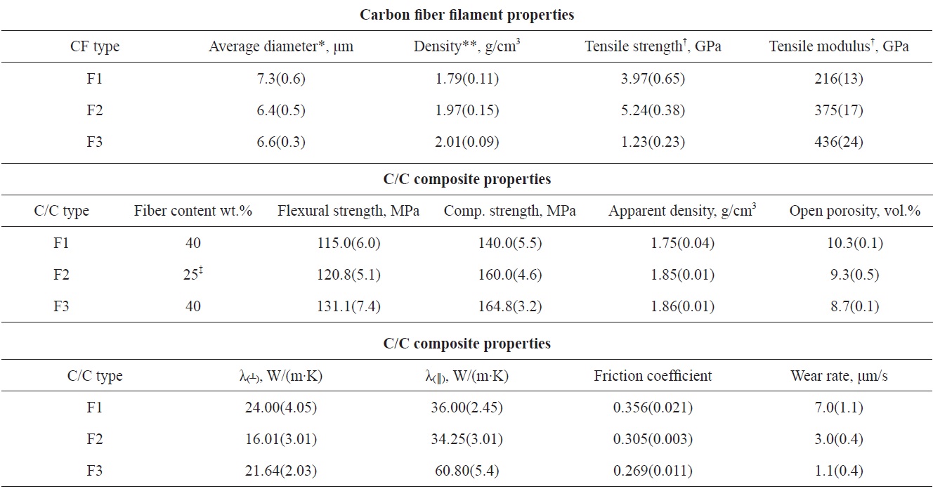
The effects of heat treatment temperature (HTT) of polyacrylonitrile-based carbon fiber (CF) on the mechanical, thermal, and tribological properties of C/C composites were investigated. It was found that HTT (graphitization) of CF affects the thermal conductivity and mechanical and tribological characteristics of C/C composites. Thermal treatment of fibers at temperatures up to 2800℃ led to a decrease of the wear rate and the friction coefficient of C/C composite-based discs from 7.0 to 1.1 μm/stop and from 0.356 to 0.269, respectively. The friction surface morphology and friction mechanism strongly depended on the mechanical properties of the CFs. The relief of the friction surface of composites based on CFs with final graphitization was also modified, compared to that of composites based on initial fibers. This phenomenon could be explained by modification of the abrasive wear resistance of reinforcement fibers and consequently modification of the friction and wearing properties of composites. Correlation of the graphitization temperature with the increased flexural and compressive strength, apparent density, and thermal conductivity of the composites was also demonstrated.
Carbon/carbon composites are widely used for the production of aircraft and automobile brakes [1,2] and potentially could be used in brakes for high-speed trains [3]. Owing to their combination of excellent mechanical properties, thermal conductivity, low density, oxidation resistance under high temperature, and good tribological characteristics, these materials are indispensable for producing brakes subjected to heavy loads and extreme application conditions [4]. However, high material cost limits the widespread application of C/C composites brakes.
The final heat treatment temperature (HTT) of carbon fiber (CF) is considered to be a critical parameter for the production of C/C composites with good friction and wear performance. It is known that the tensile modulus of polyacrylonitrile (PAN)-based CF rises when the temperature of heat treatment increases [5,6]; the thermal conductivity-temperature dependence also follows this pattern [6]. Shin et al. [7] found that the wear rate and friction coefficient of C/C composite reinforced PAN-based CF with a char matrix decreased with an increase of the fiber tensile modulus. The authors attributed this to the change of heat dissipation properties of composites such as temperature and load distributions in the contact area of friction surface. Dhakate et al. [8] compared the mechanical properties (high strength, intermediate modulus, and high modulus CF) of a C/C composite against a CF type under heat treatment. It was found that strong binding with the matrix took place due to the high content of free functional
[Table 1.] Characteristics of carbon fibers used and C/C composites produced
Characteristics of carbon fibers used and C/C composites produced
groups on the high strength CF-surface. The formed bonds possessed high stress transfer capacity. As a result, the highest volume shrinkage was obtained with a high strength CF-based C/C composite. However, the correlation between the friction mechanism of composites and the graphitization temperature of CFs has not been studied in detail. The present study examines the influence of graphitization temperature on the morphology of the friction surface and physical properties of C/C composites.
Three types of CF-reinforcement were used in the preparation of C/C composites. The first type (F1) of fiber was PAN-based CF, i.e. Panex®35 continuous tow containing 50 K filaments supplied by Zoltek (Hungary). The second (F2) and third (F3) fiber types were produced by heat treatment of the first type (F1) under temperatures of 2400 and 2800℃, respectively. Tensile strength, modulus, and density of F1, F2, & F3 fibers are presented in Table 1. Binder pitch (Bx95KS) with a softening point (SP) at 110℃ (Mettler technique, ASTM D3104 - 99(2010)) was obtained from RUTGERS (Germany). High temperature pitch (HP180M from RUTGERS, SP = 180℃ by Mettler) was used as an impregnator for the densification process.
2.2. Preparation of C/C composites
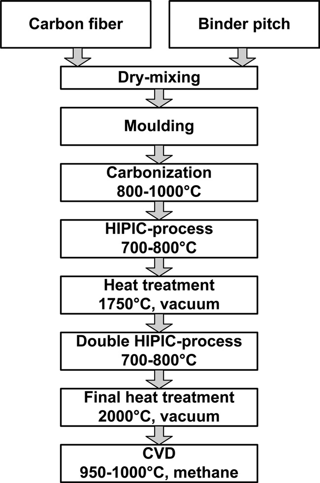
The same preparation process as employed for the C/C composites was used for each CF type. Chopped CF was used as reinforcement. Fig. 1 shows the detailed manufacturing process of the C/C composites. As a result three types of C/C composites, identified in accordance with the type of CF used, were fabricated.
2.3. Characterization of composite materials
Three discs (F1, F2, F3) were cut into samples of appropriate shapes. Apparent density and open porosity were defined by means of hydrostatic weighing: the method is similar to ASTM C20- 00(2010); sample size is 10x10x70mm. Mechanical tests were carried out on a universal testing machine (Hounsfield H5KS, UK). A hardness test was conducted by means of a Nanoindentation Tester, NanoScan-3D (FSBI TISNCM, RF). Thermal conductivity was determined in accordance with the longitudinal heat flow technique for samples in two directions (normal and parallel to the friction surface) at room temperature. Friction tests were conducted in a normal air environment using an inertia type ringon- ring configuration dynamometer. Friction coefficient and wear rate data were obtained. The microstructure and friction surface morphology were studied by means of Quanta 3D FEG scanning electron microscopy (FEI, USA). X-ray diffraction (XRD) patterns of ground-up samples of the carbon fibers and C/C composites were obtained in an X-ray diffractometer (Thermo ARL X-TRA and CuKα radiation (λ = 0.15418 nm).
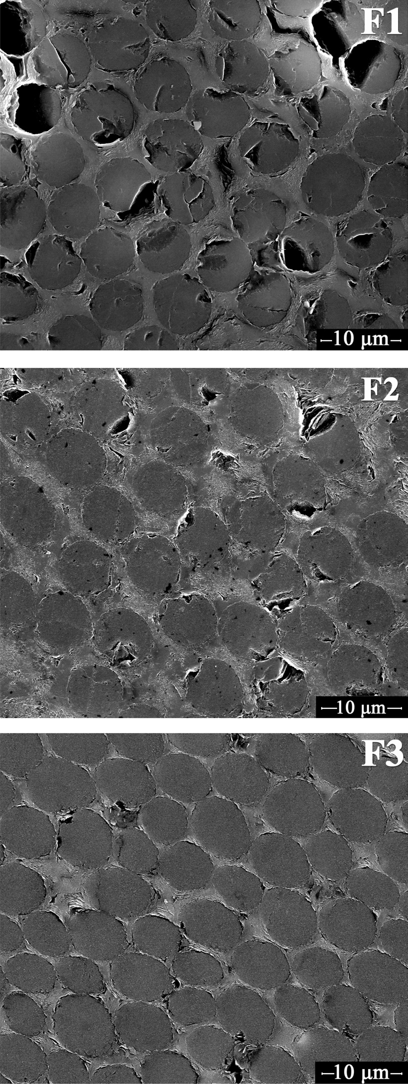
The results of mechanical and friction testing of F1-, F2-, and F3-composites are illustrated in Table 1. The increase of the tensile modulus of CF leads to a decrease of the wear rate of the C/C composite. To explain this phenomenon, a preliminary study of mechanical characteristics was carried out. Two types of composites, namely samples based on 1) high strength chopped PAN-based CF (treated under temperature of up to 1500℃) and 2) high modulus chopped graphitized PANbased CF (under 2800℃) and a pitch matrix, were used for the study. Mechanical characteristics of the reinforcement fibers and matrix were determined by means of the nanoindentation method by moving a sharp indenter normally to the composite friction surface and fiber axis. Results showed that the hardness and elastic fracture energy of high strength CF in the C/C composite were, respectively, 1.4 and 1.5 times larger than that for graphitized CF. Nanoindentation testing of the carbon matrix of the same composites gave inverse results: the hardness and elastic fracture energy of the matrix of the C/C composite, based on high strength CF, were 2 and 1.9 times smaller, respectively, than in the composite based on graphitized CF. is likely to be connected with higher shrinkage and the stress state on the reinforcement-matrix interface under heat treatment of the composite based on high strength CF [9]. This state results in the formation of a fissured structure during thin section preparation. During the preparation of polished cross-sections the stress state and strong binding of the reinforcement-matrix in the F1-composite result in cracking and destruction of the CF. As Fig. 2 illustrates, the F1-composite possesses the most fissured structure, while the structures of the F2- and F3-composites are less fissured. The
linear thermal expansion coefficient (LTEC) of CF also affects shrinkage of the reinforcement-matrix interface. The LTEC of CF is known to decrease when the tensile modulus increases [10]. Its high value leads to an increase of the matrix interface shrinkage. Furthermore, heat treatment of CF as reinforcement in the composite (at 1750℃ and 2000℃ as per preparation process) results in fiber lineal shrinkage, which creates more stress in the interface of the matrix. The hardness and elastic
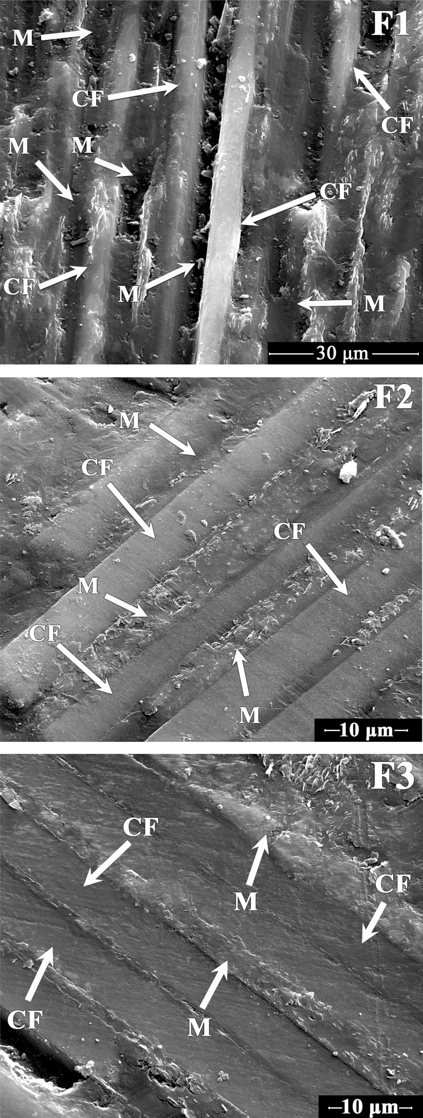
fracture energy of the reinforcement and the matrix determine the wear mechanism of C/C composites under friction. As Fig. 3 shows, the friction surface of composites, based on different tensile modulus CFs (F1, F2, & F3), possesses different morphology and relief. During friction testing of the F1-composite the fiber reinforcement primarily wears the char matrix. Debris generated in the wear process also plays a
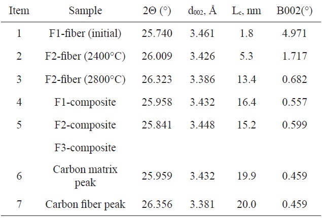
[Table 2.] Structural characteristics of carbon fibers and C/C composites studied

Structural characteristics of carbon fibers and C/C composites studied
major role [2]. CFs of the F1-composite during wear generate debris consisting of fiber pieces with a relatively high elastic fracture energy value, and the presence of this debris increases the wear rate of the F1-composite. In this case fibers and fiber debris act as an abrasive [7]. During friction testing of the F3-composite, based on graphitized CF (F3), reinforcement is primarily worn out due to the low elastic fracture energy of the fiber, and therefore debris consisting of graphitized CF crumbs is generated; this debris exhibits a self-lubricating behavior, forming a graphitic film that decreases the wear rate [11,12]. As Fig. 3 shows, in the case of the F1-composite, the CF (marked as
As Table 1 shows, with an increase of the HTT of the CF composite, the flexural and compressive strength and apparent density rise by 14%, 18%, and 5%, respectively, while open porosity falls by 18%. These results are attributed to the more fissured structure of the composite based on F1-fiber [8]. Pore structures of the composites, based on CF with different HTT, are different: the composites based on high modulus CF have slit-type pores and cracks predominantly running parallel to the fiber axis, while in the high strength CF-based composites pores running both in the fiber direction and normal to it are generated [9]. With regard to the thermal conductivity, it rises in a parallel direction: the value for F3-composite is 1,7 times higher than that for the F1-composite. Normal thermal conductivity of F1-composite is 11% higher than that of the F3-composite. This might be caused by stress-graphitization of the char matrix, which takes place in composites based on high strength CF [13]. As for the F2-composite, its low parallel thermal conductivity is likely connected with low fiber content (25 vs. 40).
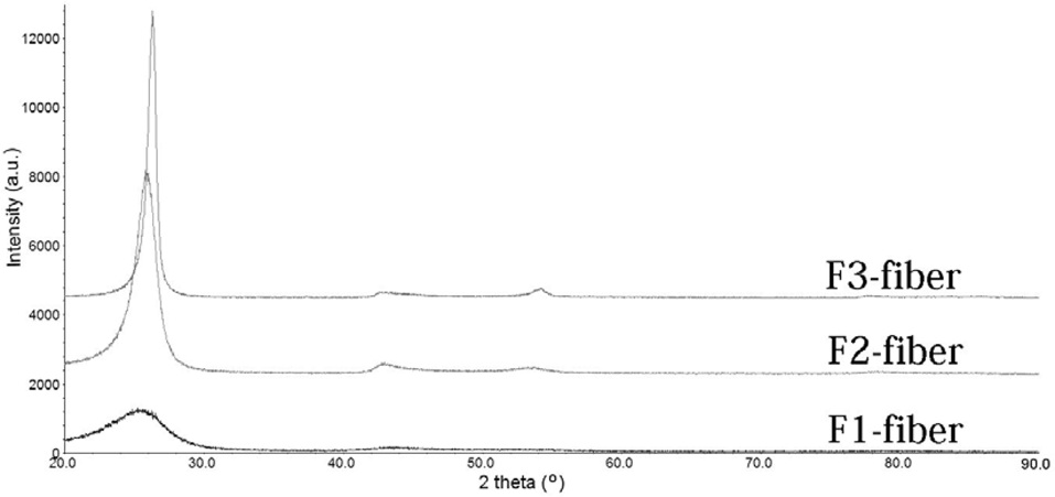
According to the data in Table 2 and Fig. 4, the increase of final heat treatment temperature for carbon fibers results correlates with the decrease of the interlayer distance (d002) and the growth of crystallite size (Lc). This behavior is typical of PAN based carbon fibers [5,14-15]. Crystallite size values of all the C/C composites under study have similar
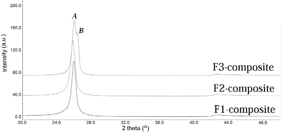
values. The size of crystallites is determined mainly by final temperature of composite heat treatment (see Fig.1). As shown in Table 2 and Fig.5, two separate peaks (А & В) with 2 Θ ~ 25.9o could be clearly seen on the X-ray pattern of F3- composite. These peaks correspond to carbon matrix and high modulus carbon fiber respectively. It should be noted that the FWHMs values were fixed equal to get stable fitting for these strongly overlapping peaks. Attempts to fit individual FWHM values for these two peaks lead to divergence of fitting procedure. F2-composite possesses higher Lc value than F2-fiber (treated under temperature of 2400°С), which apparently is associated with more intense crystallization of graphite crystallites in coal tar pitch-based coke under temperature 2000°С (see Fig.1). Peaks related to carbon matrix and carbon fiber in F2-composite completely overlap and couldn’t be separated by fitting procedure. According to the results received, the crystallinity of composites is not critical to wear mechanism.
Three types of C/C composites, samples based on a coal tar pitch-based matrix and 1) initial CF, or 2) CF, heat-treated at 2400℃, or 3) CF, heat-treated at 2800℃, were fabricated in this study. Their mechanical, thermal, and tribological properties were compared. It was found that with an increase of the HTT of the CF friction coefficient, the wear rate, hardness, elastic fracture energy of the CF in the composite, and composite open porosity decrease, whereas the hardness and elastic fracture energy of the matrix in the composite, flexural and compressive strength, apparent density, and thermal conductivity rise.