검색 전체 메뉴
PDF
맨 위로
OA 학술지
Compact Circularly Polarized Composite Cavity-Backed Crossed Dipole for GPS Applications
  • 비영리 CC BY-NC
  • 비영리 CC BY-NC
ABSTRACT
Compact Circularly Polarized Composite Cavity-Backed Crossed Dipole for GPS Applications
KEYWORD
Wide-Beamwidth , Circular Polarization , Crossed Dipole , Meander Line , Arrowhead Shaped Shape , Phase Delay Line , Cavity-Backed Reflector.
  • Ⅰ. Introduction

    The global positioning system (GPS) is the most popular member of Global Navigation Satellite Systems (GNSS) that provide location and time information about user in anywhere on the Earth [1]. GPS universally utilizes circularly polarized (CP) radiation due to Faraday rotation when signals pass through the ionosphere. In particular, GPS receiver antennas are required to have right-hand circular polarization (RHCP), a wide 3-dB axial ratio beamwidth that faces the sky, and a high front- to-back ratio to avoid interference from the ground. Various types of CP antennas were introduced to operate at GPS bands, including the microstrip antennas [2], [3], near-field resonant parasitic antennas [4], [5], crossed dipole antennas [6], and pinwheel-shaped planar monopole antennas [7]. However, most of these designs essentially focused on the CP generation or 3-dB AR bandwidth enhancement rather than improvement of the 3-dB AR beamwidth. Recently, several techniques for widening the CP radiation beamwidth have been reported, such as a pyramidal ground structure with a partially enclosed flat conducting wall [8], an auxiliary radiator [9], applying higher order modes [10], loading gaps and stubs on the patch [11], and a microstrip-monopole combination [12].

    In this paper, a compact composite cavity-backed crossed dipole is introduced as a simple way to improve the CP radiation beamwidth. The proposed design utilizes a cavity-backed reflector not only to render a unidirectional pattern but also to improve the CP radiation in terms of 3-dB AR bandwidth and beamwidth. For a compact size of radiator, two techniques are employed: insertion of meander lines in the dipole arm and shaping of the dipole arm end into arrowhead [4]. A vacantquarter printed ring is used as 90° phase delay line of crossed dipoles to produce CP radiation [6].

    Ⅱ. Antenna Design and Characteristics

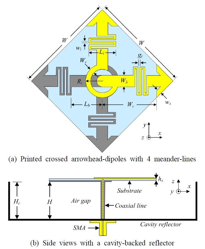
    Fig. 1 shows the geometry of the compact composite cavity-backed crossed dipole. The antenna was comprised of two printed dipoles, a cavity reflector, and a coaxial line. The cavity was a rectangular box with a dimension of 90×90 mm and a height of Hc=30 mm. The printed dipoles were placed at the center of the cavity and suspended at a height of H=30 mm from the bottom of the reflector. The coaxial line was punctured through the cavity to feed the printed dipoles. The dipoles were designed on both sides of a 42×42 mm Rogers RO4003 substrate with a permittivity of 3.38, a loss tangent of 0.0027, and a thickness of 0.2032 mm. The outer conductor of coaxial line was connected to the arms on bottom side of the substrate. The inner conductor of the feedline was extended through the substrate and connected to the arms on top side. Each dipole arm contained a meander line and an arrowhead-shaped end. The dipoles were crossed through a vacant-quarter printed ring that was acted as the 90° phase delay line. The meander line was started at Lb from the center, with a trace width of wi, and their segments had a gap size of gi and a length of Li. The ANSYS-Ansoft high-frequency structure simulator (HFSS) was used to investigate the antenna characteristics. The optimized antenna design parameters were chosen for the minimum AR at 1.575 GHz and the wide CP radiation beamwidth, as follows: W=42 mm, Wc=22.5 mm, Ri=5.4 mm, Wr=0.8 mm, Wb=4 mm, Lb=11 mm, Li=10 mm, gi=0.4 mm, wi =0.8 mm, ws=1.6 mm, hs=0.2032 mm, Hc=30 mm, and H=30 mm.

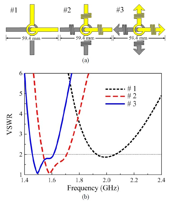
    Fig. 2(a) illustrates the process of antenna design; the initial design (design #1) was two straight dipoles crossed through the vacant-quarter printed ring. Four meander lines were then symmetrically inserted into the dipole arms (design #2). Finally, each dipole end was shaped like an arrowhead (design #3). Note that all design #1~3 were built on both sides of the 42×42 mm Rogers RO4003 substrate (εr=3.38, tanδ=0.0027, and thickness=0.2032 mm) and suspended at H=30 mm from the bottom of the 90×90 mm cavity-backed reflector. The above three structures were simulated using HFSS software and VSWRs were given in Fig. 2(b). From the simulations, the design #1 yielded the lowest resonant frequency at around 2 GHz and no resonance near the GPS band of 1.57 GHz. As shown in Fig. 2(b), design #2 yielded two resonances near 1.58 and 1.67 GHz. The arrowhead dipole (design #3) yielded lower resonant frequencies when compared with the corresponding values for design #2. Additionally, HFSS calculations showed that the thinner trace width (wi), the larger gap size (gi), and the larger arrowhead produce lower resonances, but the reduction in size is accompanied by degradation of the 3-dB AR bandwidth. These results indicate that the compact size of the primary radiation elements (42×42 mm~0.22 λ0×0.22 λ0 at 1.575 GHz) is attained by the use of meander lines in the dipole arm and the arrowhead- shaped trace at its end.

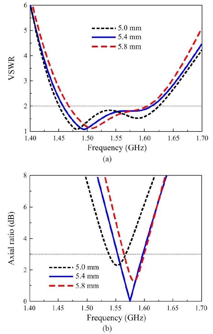
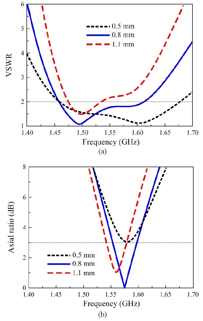
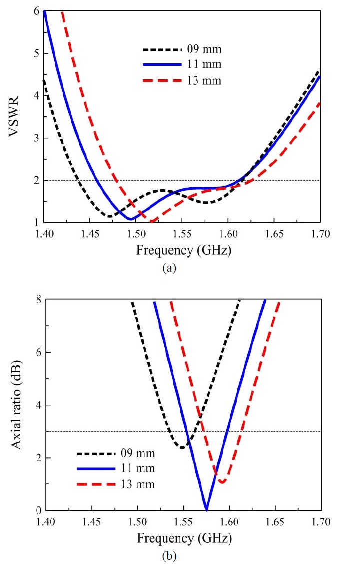
    The vacant-quarter printed ring was not only employed to produce CP radiation, but it also allowed the broadband characteristic. These capacities are observed in Figs. 3 and 4, which show simulated VSWR and AR of the antenna as a function of frequency for different radii (Ri) and widths (Wr) of the printed ring. As shown in Fig. 3, an increase of Ri slightly affected VSWR, while the CP center frequency increased. Here, the CP center frequency was defined as the frequency with minimum AR. In addition, Ri=5.4 mm offered the optimal CP radiation in terms of the widest 3-dB AR bandwidth and minimum AR. In Fig. 4, as wi was increased from 0.5 mm to 1.1 mm in increments of 0.3 mm, the impedance matching bandwidth narrowed concomitantly, while the CP center frequency decreased. The HFSS simulations indicated that the antenna with Wr < 0.5 mm yielded AR > 3 dB and Wr=0.8 mm offered the optimized results in terms of broad impedance matching and 3-dB AR bandwidths at the GPS L1 band.

    The proposed antenna employs meander lines to reduce the dipole length. The trace width of the meander lines (wi) is much smaller than the width of the dipole (Wb), so the current accumulates to an extreme degree on the meander line. This can be clearly seen in Fig. 5, which displays the simulated current distribution on the crossed dipoles at 1.575 GHz with two phase angles of 0° and 90°. It also explains the CP behavior of the proposed antenna; the vertical dipole arms worked at the phase angle of 0° and the horizontally oriented dipole arms worked at the phase angle of 90°. The arrangement of the meander lines has a significant effect on the antenna characteristics. Accordingly, the effects of the starting point of meander lines (Lb) on VSWR and AR of the antenna were studied and are shown in Fig. 6. As Lb was varied from 9 mm to 13 mm in increments of 2 mm, the resonances increased [Fig. 6(a)] and the CP center frequency also increased [Fig. 6(b)]. This result indicates that the operating frequency of the antenna can be controlled by adjusting the starting-point of the meander lines.

    Ⅲ. Measured and Simulated Results

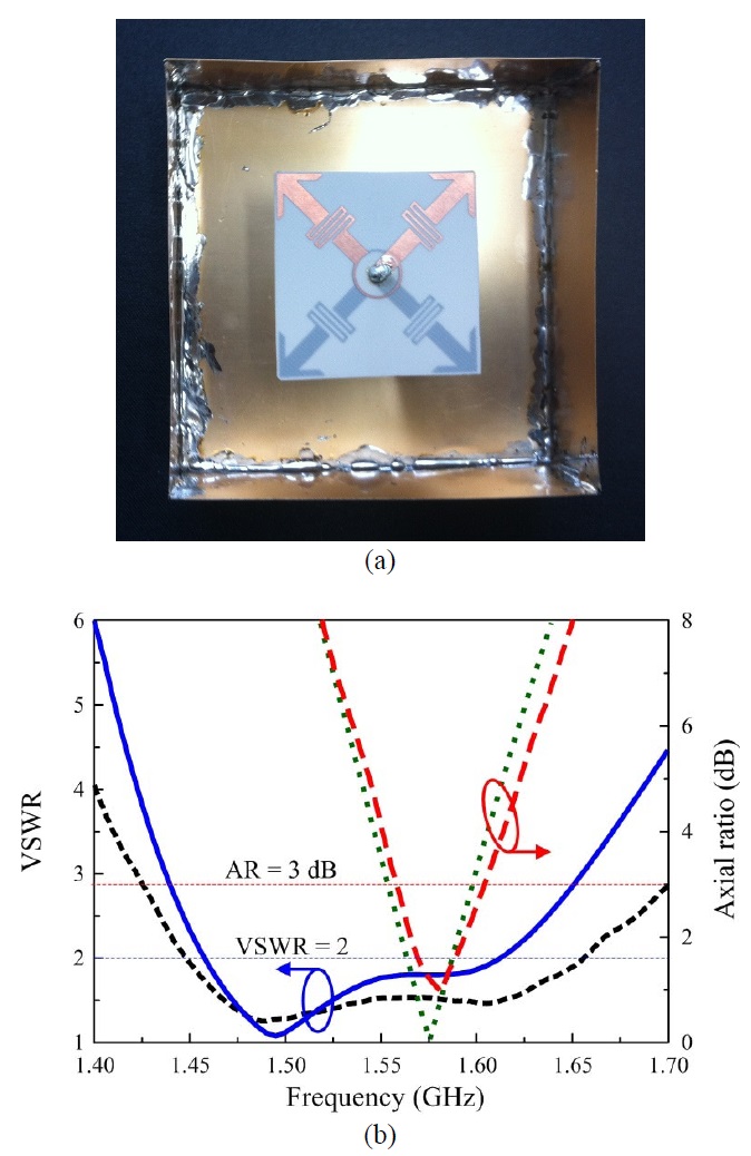
    The composite cavity-backed crossed dipole antenna was fabricated and measured. The planar crossed arrowhead dipoles were built on both sides of a Rogers RO- 4003 substrate with a copper thickness of 20 μm via a standard etching technology. The cavity-backed reflector was constructed using five copper plates (one 90×90 mm and four 90×30 mm) having a thickness of 0.2 mm. A sample of the proposed antenna [Fig. 7(a)] was used for input impedance and radiation pattern measurements. The measured and simulated VSWR of the proposed antenna are shown in Fig. 7(b). The measured bandwidth was 1.450~1.656 GHz for VSWR<2, while the simulated bandwidth was 1.458~1.613 GHz. A slight discrepancy between measurement and simulation could be attributed to the misalignment of the dipole-arms on the different sides of the substrate. The simulated and measured ARs of the proposed antenna are also shown in Fig. 7(b) and indicate a good agreement between the two. The measured 3-dB AR bandwidth was 1.555~ 1.605 GHz with the CP center frequency of 1.580 GHz (AR of 0.96 dB) while the simulated 3-dB axial ratio bandwidth was 1.554~1.597 GHz with the CP center frequency of 1.575 GHz (AR of 0.05 dB).

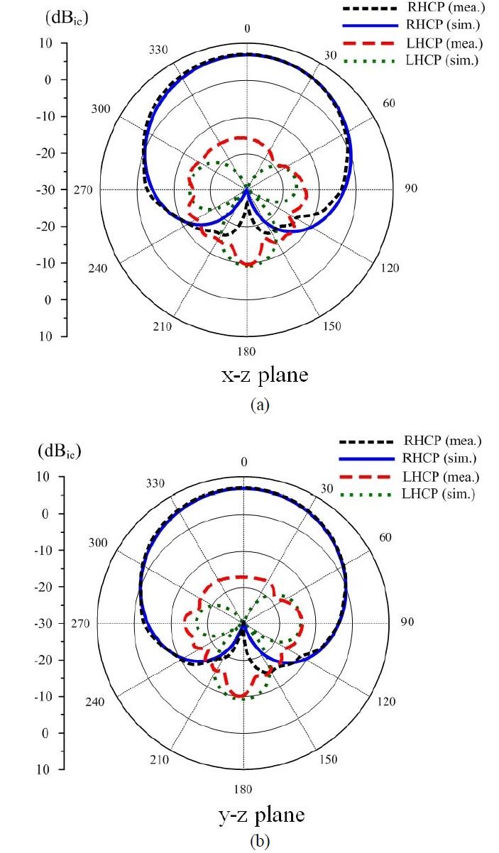
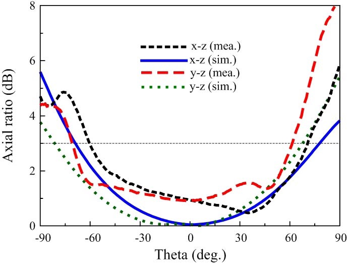
    Fig. 8 shows the 1.575 GHz radiation patterns of the antenna with RHCP, symmetrical profile, and wide beamwidth in both x-z and y-z planes. The RHCP, in particular, can be interchanged with the LHCP by reversing the vacant-quarter printed ring. The measurements yielded a gain of 7 dBic, a front-to-back ratio of 27 dB, and 3-dB beamwidths of 104° and 105° in the x-z and y-z planes, respectively. Fig. 9 shows the simulated and measured AR of the antenna versus theta angle at 1.575 GHz. The measured 3-dB AR beamwidths were 130° and 132° in the x-z and y-z planes, respectively. The simulated beamwidth for 3-dB AR were 145° and 148° in the x-z and y-z planes, respectively. The CP radiation beamwidth was slightly narrower for the measurements than for the simulations. This could be attributed to the substrate bending effects.

    Ⅳ. Conclusion

    A CP composite crossed dipole was introduced for use in GPS with broadband characteristics (1.45?1.65 GHz for VSWR < 2 and 1.555~1.605 for AR < 3) and wide beamwidth radiation (>100º for 3-dB beamwidth and > 130º for 3 dB AR beamwidth). A vacant-quarter printed ring was used as the 90º phase delay line to produce CP radiation. Arrowhead dipoles and meander lines were employed for a significant reduction of the radiator sizes. The cavity-backed reflector was utilized not only to achieve a unidirectional radiation pattern but also improve the CP radiation beamwidth. The proposed wide beamwidth antenna can be widely applied to GPS purposes, as well as to satellite communications.

참고문헌
  • 1. Enge P., Misra P. 1999 "Special issue on global positioning systems" [Proc. IEEE] Vol.87 P.3-15 google
  • 2. Lam K., Luk K., Lee K., Wong H., Ng K. 2011 "Small circularly polarized U-slot wideband patch antenna" [IEEE Antenna Wireless Propagat. Lett.] Vol.10 P.87-90 google
  • 3. Dey S., Chebolu S., Mittra R., Park I., Kobayashi T., Itoh M 1995 "A compact microstrip antenna for CP" [Antennas and Propagation Society International Symposium, AP-S. Digest] P.982-985 google
  • 4. Jin P., Lin C., Ziolkowski R. W. 2012 "Multifunctional, electrically small, planar near-field resonant parasitic antennas" [IEEE Antennas Wireless Propagat. Lett.] Vol.11 P.200-204 google
  • 5. Jin P., Ziolkowski R. W. 2012 "High directivity, electrically small, low-profile, near-field resonant parasitic antennas" [IEEE Antennas Wireless Propagat. Lett.] Vol.11 P.305-309 google
  • 6. Baik J., Lee T., Pyo S., Han S., Jeong J., Kim Y. 2011 "Broadband circularly crossed dipole with parasitic loop resonators and its array" [IEEE Trans. Antennas Propagat.] Vol.59 P.80-88 google
  • 7. Lee W., Oh K., Yu J. 2012 "A wideband circularly polarized pinwheel-shaped planar monopole antenna for wireless applications" [J. Electro-Mag. Eng. Sci.] Vol.12 P.155-160 google
  • 8. Su C. W., Huang S. K., Lee C. H. 2007 "CP microstrip antenna with wide beamwidth for GPS band application" [Electron. Lett.] Vol.43 P.1062-1063 google
  • 9. Chen Z., Toh W., Qing X. 2008 "A microstrip patch antenna with broadened beamwidth" [Microwave Opt. Technol. Lett.] Vol.50 P.1885-1888 google
  • 10. Ouyang J., Yang F., Yang S., Nie Z. 2008 "A novel E-shape radiation pattern reconfigurable microstrip antenna for broadband, wide-beam, high-gain applications" [Microwave Opt. Technol. Lett.] Vol.50 P.2052-2054 google
  • 11. Duan Z., Qu S., Wu Y., Zhang J. 2009 "Wide bandwidth and broad beamwidth microstrip patch antenna" [Electron. Lett.] Vol.45 P.249-250 google
  • 12. Wu C., Han L., Yang F., Wang L., Yang P. 2012 "Broad beamwidth circular polarisation antenna: microstrip- monopole antenna" [Electron. Lett.] Vol.48 P.1176-1178 google
OAK XML 통계
이미지 / 테이블
  • [ Fig. 1. ]  Geometry of the proposed antenna.
    Geometry of the proposed antenna.
  • [ Fig. 2. ]  (a) Dipole-length reduction process and (b) VSWR as a function of frequency for different crossed dipoles.
    (a) Dipole-length reduction process and (b) VSWR as a function of frequency for different crossed dipoles.
  • [ Fig. 3. ]  (a) VSWR and (b) AR as a function of frequency for different radii of the vacant-quarter printed ring (Ri).
    (a) VSWR and (b) AR as a function of frequency for different radii of the vacant-quarter printed ring (Ri).
  • [ Fig. 4. ]  (a) VSWR and (b) AR as a function of frequency for different widths of the vacant-quarter printed ring (Wr).
    (a) VSWR and (b) AR as a function of frequency for different widths of the vacant-quarter printed ring (Wr).
  • [ Fig. 5. ]  Simulated current distribution on the crossed arrowhead-dipoles at 1.575 GHz for two phase angles.
    Simulated current distribution on the crossed arrowhead-dipoles at 1.575 GHz for two phase angles.
  • [ Fig. 6. ]  (a) VSWR and (b) AR as a function of frequency for different starting points (Lb) of the printed inductor.
    (a) VSWR and (b) AR as a function of frequency for different starting points (Lb) of the printed inductor.
  • [ Fig. 7. ]  (a) Fabricated antenna and (b) simulation and measurement of VSWR and AR for the proposed antenna. VSWR measurement; VSWR simulation; AR measurement; AR simulation.
    (a) Fabricated antenna and (b) simulation and measurement of VSWR and AR for the proposed antenna. VSWR measurement; VSWR simulation; AR measurement; AR simulation.
  • [ Fig. 8. ]  Radiation patterns of the antenna at 1.575 GHz.
    Radiation patterns of the antenna at 1.575 GHz.
  • [ Fig. 9. ]  AR versus theta angle at 1.575 GHz.
    AR versus theta angle at 1.575 GHz.
(우)06579 서울시 서초구 반포대로 201(반포동)
Tel. 02-537-6389 | Fax. 02-590-0571 | 문의 : oak2014@korea.kr
Copyright(c) National Library of Korea. All rights reserved.