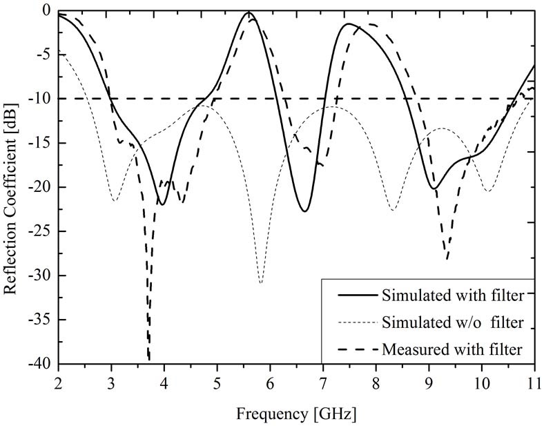
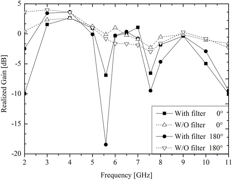
검색 전체 메뉴
PDF
맨 위로
OA 학술지
Band-Notched Ultra-Wideband Antenna with Asymmetric Coupled-Line for WLAN and X-Band Military Satellite
  • 비영리 CC BY-NC
  • 비영리 CC BY-NC
ABSTRACT
Band-Notched Ultra-Wideband Antenna with Asymmetric Coupled-Line for WLAN and X-Band Military Satellite
KEYWORD
Parallel Coupled Line , Notch-Bands , Patch Antenna , Ultra-Wideband (UWB).
  • Ⅰ. Introduction

    The allocation by the Federal Communication Commission (FCC) of the unlicensed band at frequencies between 3.1~10.6 GHz [1] for commercial purposes has resulted in rapid development of ultra-wideband (UWB) wireless communication systems. This frequency band is now in great demand in microwave components such as indoor and hand-held wireless devices, owing to its merits, particularly its good impedance matching, large bandwidth, low signal distortion and high speed of more than 100 Mbps within the operation frequency bands [2]. However, a problem arises that affects and interrupted UWB operation. For example, UWB systems will experience interference from the wireless communication bands of Wireless Local Area Network (WLAN) (5.15~5.35 GHz & 5.725~5.825 GHz) and X-band military satellite (7.25 ~7.75 GHz & 7.9~8.4 GHz). Therefore, the bands used fort WLAN and X-bands military satellite must be rejected. UWB researchers have attempted to suppress this interference by studying and investigating various band stop methods that reject the typical WLAN band or large part of it [3]~[6]. One of the methods used to suppress some interference frequencies adapt a parallel coupled line and this can demonstrate notch characteristics [7], [8].

    This paper describes a UWB monopole antenna with band-stop characteristics that uses a parallel-coupled dual- line. The asymmetric dual-line is suggested. The proposed antenna can suppress interference from strong narrow and broad by controlling the asymmetric dual-line. However, this solution can only reject planned interference bands. The operation characteristics in UWB, which eliminates influences related to WLAN and X-band military satellite, are advanced by determining and optimizing the proposed antenna by a parasitic line in a parallel- coupled line. Additionally, to achieve the good impedance matching, the bottom GND of the proposed antenna is modified by cutting rectangular slot on the center edge and symmetrical rectangular slots on the right and left edge [9]. These adaptations allowed the optimal design, fabrication, and measurement of a UWB notch antenna with an asymmetric dual-line.

    Ⅱ. Antenna Geometry

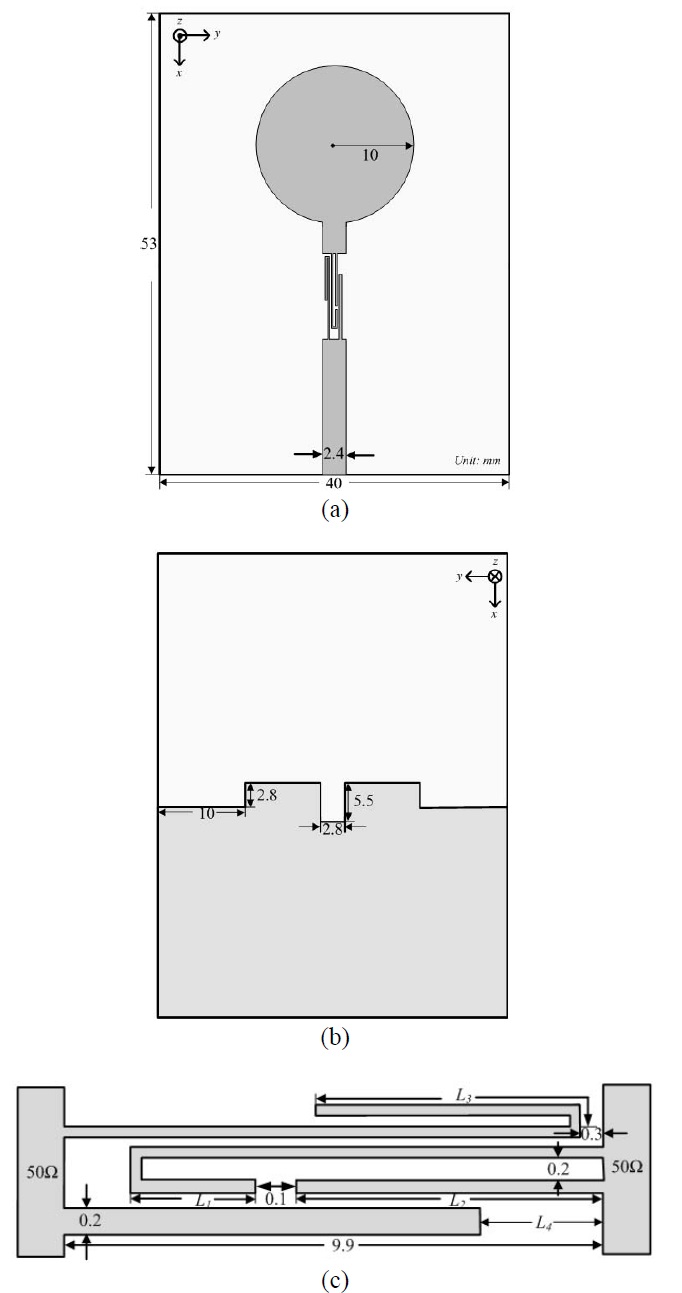
    The configuration of the UWB printed antenna for band-notch characteristics is proposed in Fig. 1(a) and (b). The proposed antenna consists of a circular patch radiator and a parallel-coupled asymmetric dual-line on a Taconic substrate with a size of 53 mm×40 mm, thickness of 1.14 mm, and relative permittivity 2.2. The adopted circular patch is operated as a radiating function and the microstrip feed line is fixed at 2.4 mm to activate 50-Ω characteristic impedance at 3.1~10.6 GHz. The detailed parallel-coupled asymmetric dual-line of the proposed antenna is shown in Fig. 1(c). Based on these points, the parameters are as follows: the parameters follow as: L1=2.2 mm, L2=6.3 mm, L3=5 mm, L4=2.3 mm. The gap between the strips in the parallel-coupled strips in parallel-coupled line is 0.1 mm except for the 0.2 mm previously mentioned. This interdigital coupled-line structure generates a higher current density and phase transit so that it can activate a notched band under the operation passband [10]. The reason for forming a cut-off frequency is so that the parallel coupled-line structure can achieve high tight coupling [11]. The band-notch bandwidths can be controlled by parameter analysis with the length L1 and L2 in a parallel-coupled dual-line. When the values of L1 and L2 differ, this can be used as a cut-off characteristic for the two different frequency bands. In contrast, when the values of L1 and L2 is are identical, the band-notched effect occurs at one frequency band. As shown in Fig. 2, the asymmetric dual-line is also available to reject the two band-notches by controlling L1 and L2. The proposed antenna also takes into consideration that parasitic line L3 and L4 are suitable for shifting to suppress the specified frequency WLAN and X-band military satellite bands independently. The simulated frequency responses of the parametric analysis with L3 and L4 are depicted in Fig. 3(a) and (b). Consequently, the higher band (X-band military satellite band) shifts to low when L3 is increased. Conversely, the lower band (WLAN) moves to high when L4 is increased.

    Ⅲ. Simulated and Measured Results

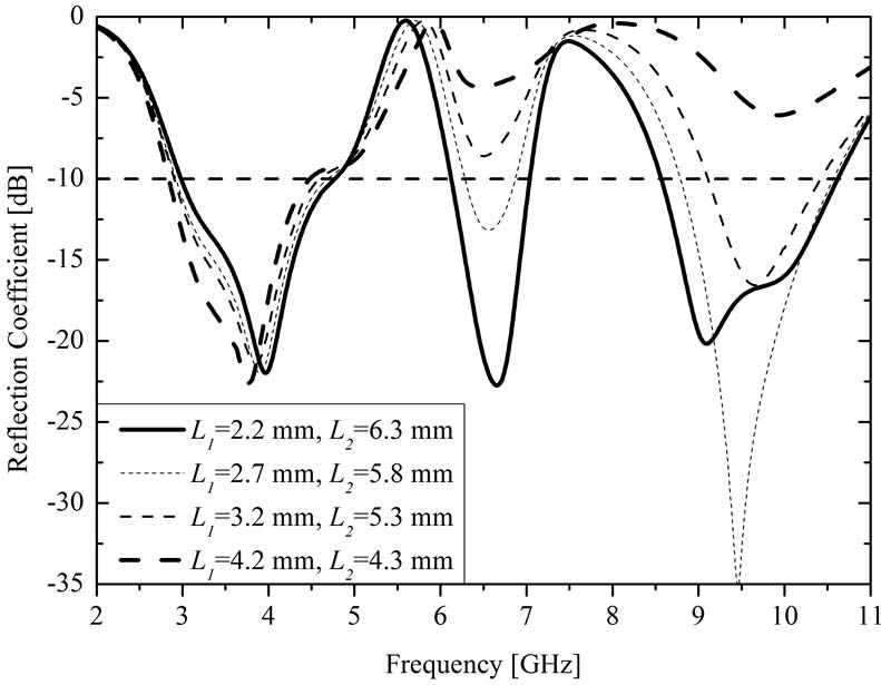
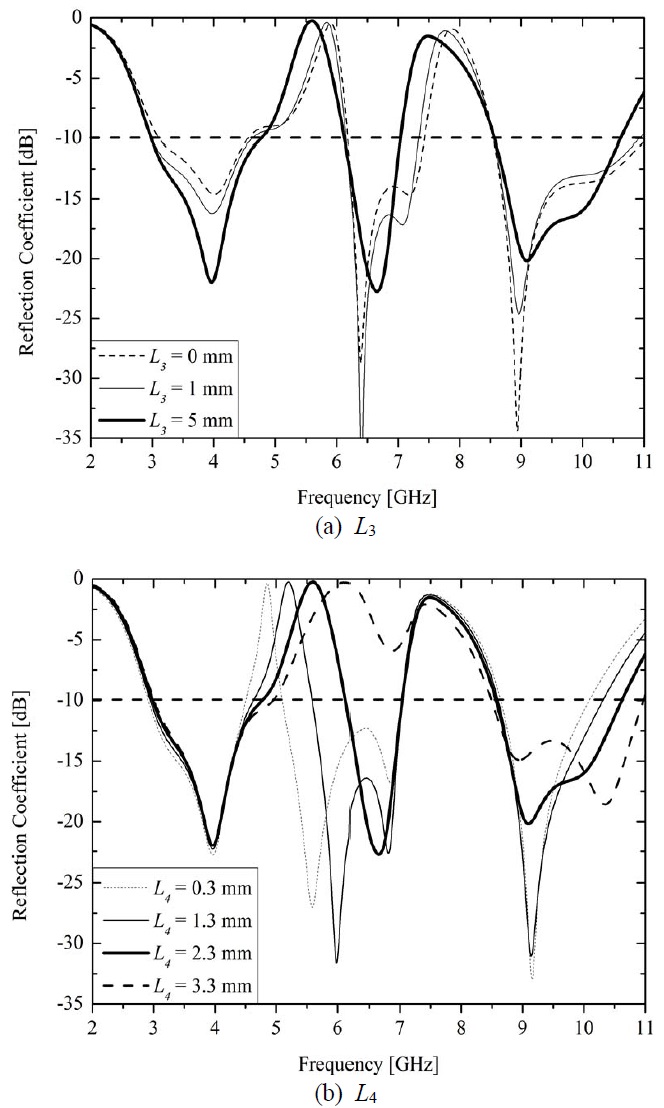
    The proposed UWB antenna is simulated using electro- magnetic simulation tools HFSS and measured using Wiltron 3605B network analyzer at the frequency from 2 GHz to 11 GHz. By adopting the methods of a different length for L1 and L2 and tuning the parasitic length L3 and L4, the WLAN and X-band military satellite bands are bypassed. Fig. 4 shows the simulated and measured reflection coefficient (dB) with and without the asymmetric dual-line (S11<?10 dB). The result is somewhat different between the simulated and measured value, which shifts to and upper frequency about 20 MHz. These results satisfy the planned bandwidth with only a slight error in measurement. The simulated and measured radiation patterns are shown as E-plane and H-plane in Fig. 5(b) and (c). The proposed fabrication has dipole-like stable and omnidirectional radiation patterns across all the operation bands. Finally, the realized gain is shown for the simulated result at two angles 0° and 180° in Fig. 6. Consequently, a rapid decrease occurs at notch frequencies when the band-notched dual-line is added at 0° and 180°.

    Ⅳ. Conclusion

    This work proposes a shorted monopole antenna with a coupled UWB antenna with asymmetric dual-line for notch characteristics has been proposed. We adapted an asymmetric dual-line and confirmed the rejection of narrow and broad bands (5.15~5.85 GHz & 7.25~8.4 GHz). The band-notch frequencies are tuned by adjusting reasonable values through parameter analysis. The results obtained using the proposed antenna have been promising, and hence, this antenna appears to be suitable for use in UWB communication systems.

참고문헌
  • 1. 2002 "First report and order, revision of part 15 of the commission's rule regarding ultra-wide band transmission systems" google
  • 2. Oppermann I., Hamalainen M., Iinatti J. 2004 UWB Theory and Applications P.3-4 google
  • 3. Peng Lin, Ruan Cheng-Li 2011 "UWB band-notched monopole antenna design using electromagnet- bandgap structures" [IEEE Trans. on Microw. Theory and Techniques] Vol.59 P.1074-1081 google
  • 4. Wu Sung-Jung, Kang Cheng-Hung, Chen Keng-Hsien, Tarng Jenn-Hwan 2010 "Study of an ultra wideband monopole antenna with a band-notched open looped resonator" [IEEE Trans. Antennas. Propag.] Vol.58 P.1890-1897 google
  • 5. Liu J., Gong S., Xu Y., Zhang X., Feng C., Qi N. 2008 "Compact printed ultra-wideband monopole antenna with dual band-notched characteristics" [Electron. Lett.] Vol.44 P.710-711 google
  • 6. Yu Chao, Hong Wei, Chiu Leung, Zhai Guohua, Yu Chen, Qin Wei, Kuai Zhenqi 2011 "Ultrawideband printed log-periodic dipole antenna with multiple notched bands" [IEEE Trans, Antennas, Propag.] Vol.59 P.725-732 google
  • 7. Shaman Hussein, Hong Jia-Sheng 2007 "Asymmetric parallel- coupled lines for notch implementation in UWB filters" [IEEE Microw. and Wirel. Compon. Lett.] Vol.17 P.516-518 google
  • 8. Song K., Xue Q. 2010 "Asymmetric dual-line coupling structure for multiple-notch implementation in UWB bandpass filters" [Electron. Lett.] Vol.46 P.1388-1390 google
  • 9. Azim R., Islam M. T., Misran N. 2011 "Ground modified double-sided printed compact UWB antenna" [Electron. Lett.] Vol.47 P.9-11 google
  • 10. Sun Sheng, Zhu Lei 2006 "Capacitive-ended interdigital coupled lines for UWB bandpass filters with improved out-of-band performances" [IEEE Microw. and Wirel. Compon. Lett.] Vol.16 P.440-442 google
  • 11. Song K., Fan Y. 2009 "Compact ultra-wideband bandpass filter using dual-line coupling structure" [IEEE Microw. Wirel. Compon. Lett.] Vol.19 P.30-32 google
OAK XML 통계
이미지 / 테이블
  • [ Fig. 1. ]  (a) Top layer, (b) bottom layer, (c) topogoly of the proposed asymmetric notch design.
    (a) Top layer, (b) bottom layer, (c) topogoly of the proposed asymmetric notch design.
  • [ Fig. 2. ]  Comparisons of simulated reflection coefficient for various lengths L1 and L2 in asymmetric coupledline.
    Comparisons of simulated reflection coefficient for various lengths L1 and L2 in asymmetric coupledline.
  • [ Fig. 3. ]  Comparisons of simulated reflection coefficients for various lengths
    Comparisons of simulated reflection coefficients for various lengths
  • [ Fig. 4. ]  Simulated and measured reflection coefficient (dB) with and without a notch coupled-line.
    Simulated and measured reflection coefficient (dB) with and without a notch coupled-line.
  • [ Fig. 5. ]  Simulated and measured 2D radiation patterns of proposed antenna.
    Simulated and measured 2D radiation patterns of proposed antenna.
  • [ Fig. 6. ]  Realized gain (dB) of the proposed antenna.
    Realized gain (dB) of the proposed antenna.
(우)06579 서울시 서초구 반포대로 201(반포동)
Tel. 02-537-6389 | Fax. 02-590-0571 | 문의 : oak2014@korea.kr
Copyright(c) National Library of Korea. All rights reserved.