The problem of spacecraft attitude control is solved using an adaptive neuro-fuzzy inference system (ANFIS). An ANFIS produces a control signal for one of the three axes of a spacecraft’s body frame, so in total three ANFISs are constructed for 3-axis attitude control. The fuzzy inference system of the ANFIS is initialized using a subtractive clustering method. The ANFIS is trained by a hybrid learning algorithm using the data obtained from attitude control simulations using state-dependent Riccati equation controller. The training data set for each axis is composed of state errors for 3 axes (roll, pitch, and yaw) and a control signal for one of the 3 axes. The stability region of the ANFIS controller is estimated numerically based on Lyapunov stability theory using a numerical method to calculate Jacobian matrix. To measure the performance of the ANFIS controller, root mean square error and correlation factor are used as performance indicators. The performance is tested on two ANFIS controllers trained in different conditions. The test results show that the performance indicators are proper in the sense that the ANFIS controller with the larger stability region provides better performance according to the performance indicators.
Spacecraft attitude control is an important aspect of performing many space missions. There has been a lot of interest in designing an accurate and stable controller for attitude control. Recently, state-dependent Riccati equation (SDRE) controllers have been introduced and applied to spacecraft attitude control. An SDRE controller produces a robust and suboptimal control signal, and is relatively easy to implement in nonlinear systems (Chang et al. 2009, 2010, Abdelrahman et al. 2011, Abdelrahman & Park 2011, Park et al. 2011). But despite its benefits, it has some drawbacks: 1) there is no systematic way to determine optimal value for weighting matrices which affects the optimality of the controller. 2) It can be difficult to derive state dependent coefficient (SDC) matrix if the plant system is highly nonlinear and complex. 3) From the perspective of real time application, it presents a high computational burden because it is necessary to update the solution of the Riccati equation every sampling time.
To provide a solution to the third of the problems mentioned above, adaptive neuro-fuzzy inference system (ANFIS) can be used, as it can model any system once it is given the input-output data pairs of the original system. ANFIS was first introduced by Jang (1993), and has been used by many researchers in control and nonlinear system identification (Jang & Sun 1995, Buyukbingol et al. 2007, Ghomsheh et al. 2007, Hua & Hengxin 2008, Sivarao et al. 2009, Tahmasebi & Hezarkhani 2010, Baseri & Alinejad 2011, Pratama et al. 2011). ANFIS is a combination of a neural network and a fuzzy inference system, and it is based on the TS fuzzy model (Takagi & Sugeno 1985). The fuzzy inference system uses a linguistic variable so that it can incorporate the experiences of human experts, but there used to be hardly any method of constructing a fuzzy inference system in a systematic way. Neural networks have the capacity of learning from data to update adaptive parameters, but do not have any kind of specific structure for system identification. In this respect, the neural networks and fuzzy inference system can help each other by compensating for each other’s weak points. By taking the advantages from both of them, ANFIS comes out. Therefore ANFIS has a structural way of identifying a specific system using the power of learning of neural networks.
Abdelrahman et al. (2010) proposed a method of applying ANFIS to spacecraft attitude control to reduce the computational load on the SDRE controller. In their approach, ANFIS is trained using the training data obtained from attitude control simulations using an SDRE controller so that ANFIS can mimic the control signal of the SDRE controller with respect to the state error. The same approach is adopted in this paper with some modifications: 1) to model the SDRE control system more accurately, coupled training data is used, while Abdelrahman et al. (2010) used decoupled training data. 2) To deal with the multiple input variables, the subtractive clustering (SC) method proposed by Chiu (1994) is used for initialization of the fuzzy inference system of ANFIS. The procedure for training the ANFIS is offered by Jang et al. (1997) as a hybrid learning rule.
Another viewpoint of this paper is in the stability region estimation and performance indicator of ANFIS controller. To estimate the stability region of ANFIS using Lyapunov stability theory, it is necessary to calculate the Jacobian matrix of the control system. The Jacobian of the ANFIS control system is hard to obtain analytically, so a numerical SDC formulation proposed by Vaddi et al. (2009) is used to calculate the Jacobian matrix numerically. Root mean square error (RMSE) and correlation factor (CF) are calculated as performance indicators for the system identification capability of the ANFIS controller.
2. ANFIS CONTROLLER FORMULATION
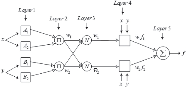
ANFIS consists of 5 layers, and each layer has several adaptive nodes. The nodes are adaptive in that they contain adaptive parameters. ANFIS is based on the Takagi-Sugeno (TS) fuzzy model,
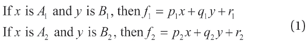
and is illustrated in Fig. 1 for the two rule case (Jang et al. 1997). The functions of the nodes in each layer are as follows:
Layer 1: the node output in this layer is membership function for input variables.
Q1,i = μAi (x), i=1,2
Q1,i = μBi-2 (y), i=3,4
Layer 2: the node output in this layer is product of the membership functions for each variable, which is called
In this paper, Gaussian membership functions are used.
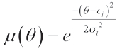
where
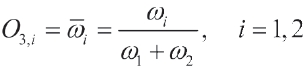
Layer 3: the node output in this layer is a normalized firing strength.
Layer 4: the node output in this layer is
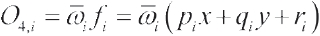
where
Layer 5: the node output in this layer is the summation of all rules’ output.
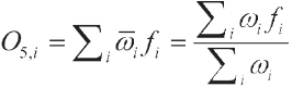
In Layers 1 and 2, all possible membership function values are obtained for each input, and the firing strength is ready for each rule as a product of membership functions. In Layers 3 and 4, each rule’s output is ready for summation in Layer 5, which produces the output of ANFIS.
The purpose of training ANFIS is to model the SDRE control system so that ANFIS can produce a control signal that is as close as possible to the control signal obtained by SDRE controller with the same state error. The coupled training data used in this paper contains 6 error states and 1 corresponding control signal in a pair as described below,
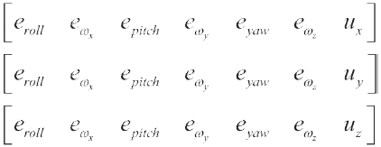
where (
For training data containing many input variables, it is not adequate to use a grid partitioning method because the number of rules in ANFIS increases exponentially with the number of inputs. For example, 2 membership functions for 6 inputs means 26 rules. The number of rules, however, is not dependent on the number of membership functions or input variables in SC, but is dependent on the cluster size. Therefore, as an initialization of ANFIS, SC (Chiu 1994) is used.
After the fuzzy inference system is initialized by SC, the ANFIS training process starts. The process is divided into two sequences according to the hybrid learning method proposed by Jang et al. (1997). One is to update the premise parameter and the other is to update consequent parameters. Least squares estimator is used for consequent parameter updating, and back propagation is used for premise parameter updating.
3. SDRE CONTROLLER FORMULATION
To apply SDRE controller to the attitude control problem, the spacecraft dynamics are represented by angular velocity and the vector part of quaternion as follows (Chang et al. 2008),
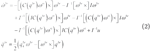
where
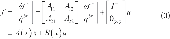
where
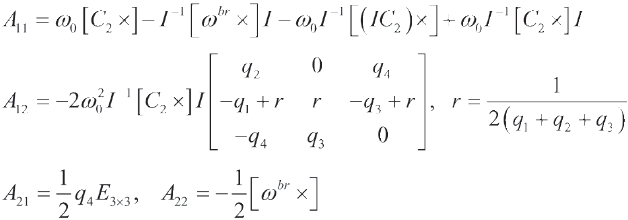
and
Using Eq. (3), the SDRE can be formulated as follows
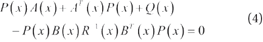
Once

Eq. (5) is the control signal to minimize a performance index represented by
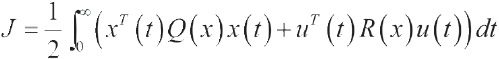
4. LYAPUNOV STABILITY AND PERFORMANCE INDICATOR OF ANFIS
4.1 Stability Region Estimation
Proposed by Bracci et al. (2006), a numerical method to estimate the region of attraction of the SDRE-controlled systems has been successfully applied to the attitude control problem by Chang et al. (2008). The method is as follows:
To apply this method, the dynamics in Eq. (3) are linearized around the equilibrium point.
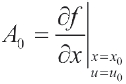
where
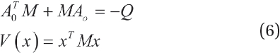
and time derivative of the Lyapunov function can be obtained as follows.

In Eq. (6),

is the stability region. This method is applied to estimate the stability region of the SDRE controller and the ANFIS controller proposed in this paper.
4.2 Performance Indicators of ANFIS
Aldrian & Djamil (2008) applied ANFIS to predict daily rainfall and presented RMSE and CF as performance indicators to check the effectiveness of the given ANFIS in modeling the original system. The two performance indicators are formulated as follows.
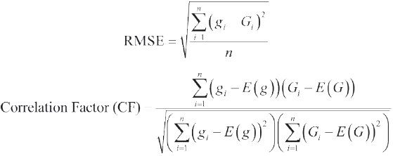
where
Simulations have been carried out to test the performance of ANFIS controller when it is applied to the attitude control problem. The spacecraft is assumed to be on the low Earth orbit 600 km above the Earth’s surface, and the orbit is assumed to be circular. The spacecraft moment of inertia is assumed to be
for Euler angles and angular velocity, respectively.
5.2 Test and Simulation Results
Stability region of SDRE and ANFIS control system has been estimated using the Lyapunov-theory-based method proposed by Bracci et al. (2006) (see Section 4). This method requires the calculation of the Jacobian matrix of the control
system. However, it is very difficult to get the Jacobian matrix of ANFIS control system using analytical calculation. To solve this problem, the numerical SDC formulation proposed by Vaddi et al. (2009) has been applied to calculate the Jacobian matrix. The angular velocity vector is fixed to [0.5730 0.5730 0.5730] deg/
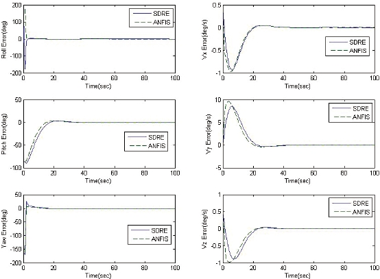
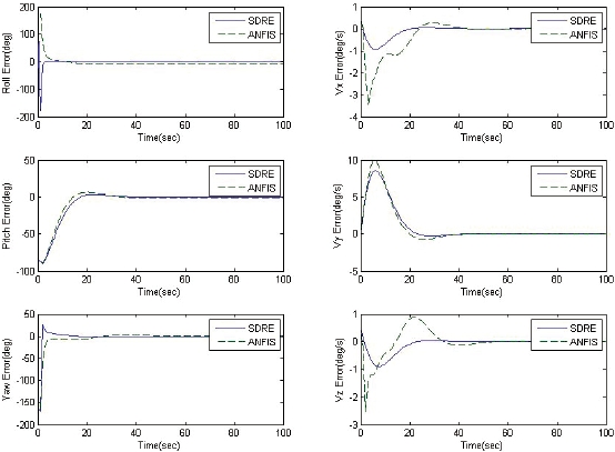
different ANFISs which are trained in different conditions; that is, cluster size in SC (i.e. number of rules) and training data configuration. How well the ANFIS is trained is measured in this paper by the size of the stability region. A well-trained ANFIS controller is an ANFIS controller whose stability region contains 199 states of the total of 1,000 test states, while the ill-trained ANFIS controller is an ANFIS controller whose stability region contains 91 states.
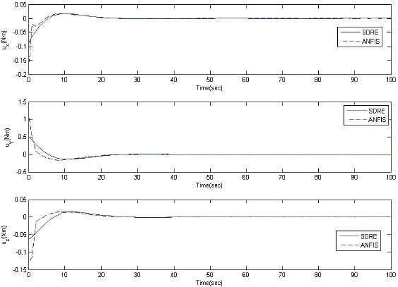
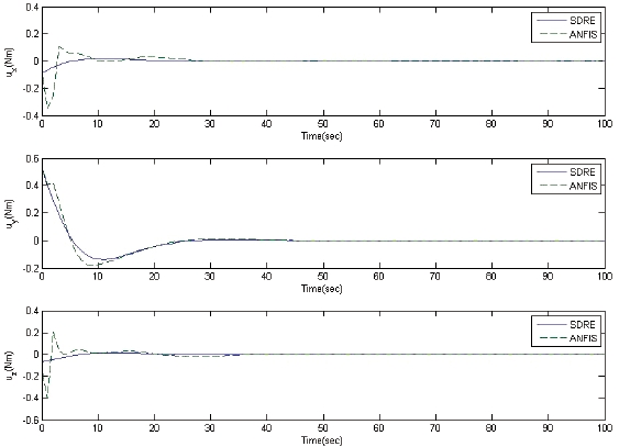
The performance of the well-trained ANFIS controller is compared to that of the SDRE controller and that of the ill-trained ANFIS controller. Figs. 2 and 3 show state error history of well-trained and ill-trained ANFIS control systems, respectively, using the initial conditions mentioned above. Figs. 4 and 5 show the corresponding control signal history for the two ANFIS control systems. We can see that the well-trained ANFIS control system trajectories
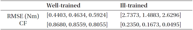
[Table 1.] Performance indicators.

Performance indicators.
follow the SDRE control system trajectories more closely. The performance indicators (RMSE and CF) have been calculated using the 1,000 test data sets obtained randomly from uniform distribution in the range of [-180, 180] deg for Euler angles and [-1, 1] deg/
6. CONCLUSIONS AND DIRECTIONS FOR FUTURE RESEARCH
ANFIS controller is constructed and applied to the attitude control problem. The ANFIS controller is trained using data obtained by attitude control simulations using an SDRE controller. The fuzzy inference system of ANFIS is initialized by SC with 6 input variables. RMSE and CF are used to test the performance of the ANFIS controller, and stability region of the controller is estimated using numerical SDC formulation based on Lyapunov stability theory. The ANFIS performance is shown to be dependent on the number of rules of ANFIS and the training data configuration. Through a comparison between well-trained and ill-trained ANFIS, the performance indicators are shown to be adequate indicators. However, the range of the stable region of the ANFIS control system does not cover all test state regions with fixed angular velocity, while the SDRE control system appears to be globally asymptotically stable. Moreover, the numerical error possibly caused by numerical SDC formulation has not been considered. Nevertheless, the results shown in this paper allow us to confirm the usability of ANFIS controller. Future research should pursue the design of a globally stable ANFIS controller.