A Ground Based Augmentation System (GBAS) is an enabling technology for an aircraft’s precision approach based on a Global Navigation Satellite System (GNSS). However, GBAS is vulnerable to interference, so effective GNSS interference detection and mitigation methods need to be employed. In this paper, an intentional GNSS interference detection and characterization algorithm is proposed. The algorithm uses Automatic Gain Control (AGC) gain and adaptive notch filter parameters to classify types of incoming interference and to characterize them. The AGC gain and adaptive lattice IIR notch filter parameter values in GNSS receivers are examined according to interference types and power levels. Based on those data, the interference detection and characterization algorithm is developed and Monte Carlo simulations are carried out for performance analysis of the proposed method. Here, the proposed algorithm is used to detect and characterize single-tone continuous wave interference, swept continuous wave interference, and band-limited white Gaussian noise. The algorithm can be used for GNSS interference monitoring in an excessive Radio Frequency Interference environment which causes loss of receiver tracking. This interference detection and characterization algorithm will be used to enhance the interference mitigation algorithm.
The GNSS signal power level at a receiver is extremely low. Therefore, radio frequency interference (RFI) is a serious concern, particularly for GNSS-based safetycritical systems such as the Ground Based Augmentation System (GBAS). Non-Fed CAT I GBAS was approved by FAA in September 2009. However, its operational stability test failed due to a privacy jammer’s intentional interference. This incident showed that the GBAS was not designed robustly against intentional jamming. After upgrading GBAS software and implementing a physical configuration change and law enforcement against jamming, the system became more stable but it is still vulnerable to excessive radio frequency interference [1]. GBAS equipment’s RFI requirement in ICAO ANEX 10 states that GBAS receivers shall not output misleading information in the presence of interference levels exceeding the specified RFI mask, which are -120.5 dBm for inband continuous wave interference and -110.5 dBm/MHz for broadband interference [2]. These requirements ensure safe flight operation by making the receivers provide navigation information only in a normal radio frequency environment. However, for safe flight operation, there should be a system which provides situational awareness even in an excessive radio frequency interference environment. This is especially true in Korea. In the past two years, South Korea has experienced intentional GPS jamming several times. By investigation, it was found that the incident was due to North Korea’s intentional jamming and the types of jamming signals were single-tone continuous wave on L1, and swept continuous wave on L2 and L5 frequency bands [3]. GPS jammers in place near the Demilitarized Zone (DMZ) could easily disrupt GPS signals in Incheon international airport from 50 kilometers away. Therefore, providing timely alert by detection and characterization of GNSS RFI, and eliminating the possible cause in a timely manner are important to ensure safe flight operation based on the GBAS.
There are various methods to detect GNSS interference. They are mainly classified as the pre-correlation detection method and the post-correlation detection method depending on where the algorithms are applied. Antenna, AGC and ADC have been used to detect and characterize the RFI in pre-correlation techniques [4-7], while receiver observables like C/No, phase distortion, and pseudo-range step measurements are used for post-correlation techniques [8-11]. For most civil applications, post correlation detection methods using receiver observables have been preferred because they do not require additional hardware modification. However, post-correlation methods can be used only when a receiver is tracking the GNSS signal, so the methods are not adequate for characterization of intentional interference whose power is above a civil receiver’s tracking threshold. Also, post-correlation methods require more time to detect interference than pre-correlation methods because C/No estimation requires an averaging time of approximately 1 second to achieve unbiased estimation results [12]. To overcome these limitations, this paper is focused on the pre-correlation method using AGC gain and adaptive lattice IIR filter parameters, which can be used for intentional interference which causes loss of tracking. The algorithm is developed to detect and characterize single-tone continuous wave interference, swept continuous wave interference and band-limited white noise, which are the most common intentional interferences [4]. For the verification and performance evaluation of the proposed algorithm, GPS signal data in various interference scenarios are generated using a GPS and interference simulator. The performance of the algorithm was analyzed by Monte Carlo simulation and the simulation results showed that the algorithm is capable of detection and characterization of the specified intentional interferences.
This paper is organized as follows: the GPS signal and interference simulator are described in section 2. In section 3, the AGC model and adaptive lattice IIR notch filter parameters are explained and section 4 describes the proposed interference detection and characterization algorithm. The algorithm’s performance is evaluated in section 5 and finally section 6 concludes this paper.
2. GNSS Signal and Interference Simulator
GNSS signals are modeled differently depending on the signal modulation scheme. However, the proposed interference detection and characterization algorithm utilizes the signals before the correlation process, so considering every different modulation scheme is not necessary for the development of the algorithm. In this paper, a MATLAB SIMULINK-based GPS L1 signal and interference simulator is used to assess AGC gains and generate IF signal data in various interference scenarios [13]. The simulator generates a GPS L1 C/A signal, which is modeled as Eq. (1).

where A is IF signal amplitude,
The Additive White Gaussian Noise (AWGN) is modeled by a variance of
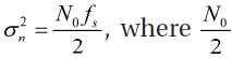
is the power spectral density of the noise and


where
The band-limited white noise is generated using the bandlimited white noise block and band pass filter block. Using the simulator, users can select the type of interference and adjust power and duration. The simulator generates the GPS signal and combines it with noise and interference, then the signal goes through band pass filter, AGC, ADC blocks and it is saved to a file in binary format. Also, AGC gain values are saved to a file which will be used as a database for AGC characterization.
3. AGC and Adaptive Lattice IIR Notch Filter Parameters for Interference Detection
3.1.1 AGC model
The Automatic Gain Control (AGC) in a Global Navigation Satellite System receiver is used to adjust the power level of the IF signal at the input to the Analog-to-Digital Converter (ADC) to minimize the quantization loss [15]. The AGC level as an interference assessment tool has been investigated before [16]. In GNSS receivers, where the signal power is below the thermal noise floor, the AGC is driven by the ambient noise or interference rather than the signal power. The interfering signal is a main source that changes the AGC gain. Therefore, AGC can be a valuable tool for assessing the interference [2,17]. AGC is sensitive to both wide band noise and continuous wave interferences. In addition, its gain responds differently depending on the type of interferences [2,17,18]. Therefore, if a receiver’s AGC is characterized against various interferences in advance and an incoming interference type is known, interference power can be estimated from the receiver’s AGC gain. In this paper, the simulator’sAGC gain response was examined according to different types of interference and the data were used for power estimation of interference sources.
As previously mentioned, without intentional jamming, the thermal noise with Gaussian distribution dominates the received signal power strength. The RMS amplitude of the thermal noise plus jamming noise must remain essentially constant at the input of the ADC. When RF interference occurs, the action of the AGC is to rapidly reduce the gain in order to maintain the original RMS level at the input of the ADC. The analog gain control voltage has an effect on the gain of the AGC as follows:

where:
The two coefficients are different depending on manufacturers, and even the same front-end models have slightly different characteristics [17]. However, if an AGC has a preplanned design and it is characterized for a receiver in interference environments, the receiver’s AGC gain values can be used for interference detection [19]. For algorithm development, the GNSS signal and interference simulator is adapted an exponential AGC model which is controlled by a digital feedback loop and 8 bit ADC. AGC gain values in different interference scenarios are saved for characterization.
3.1.2 AGC Characterization
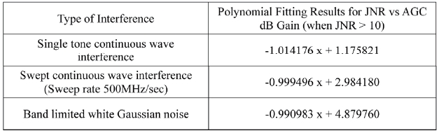
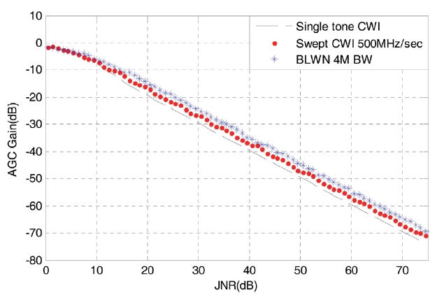
This section presents an analysis of the interference effects on AGC gain according to the types of interference at different power levels. Interference types used for AGC characterization include single-tone continuous wave interference at a GPS center frequency, swept continuous wave interference with 500MHz/sec in a 4 MHz band width, and band limited white noise in a 4MHz band width. The received GPS signal power level was set to -155dBW, and power spectral density of the Additive White Gaussian Noise was assumed to be -204dBW/Hz. The GNSS signal and interference simulator generates signals by increasing interference power and AGC gain values are logged in a file. The AGC Characterization results are shown in Fig 1. AGC gain decreases as JNR increases with different gradient depending on the type of interference. Singletone continuous wave interference affects the gain of AGC the most, while band-limited white noise affects the gain of AGC the least. This tendency is correspondent to the results in [17]. Different types of interference affect the AGC gain differently and those effects can be characterized. From JNR 10dB, AGC Gain and JNR are linear in dB. Therefore, if the type of interference is known, it is possible to estimate JNR from AGC gain using this characterization results. The polynomial fitting results of the JNR versus AGC gain are in Table 1. The remaining problem of interference classification is solved by the algorithm using the adaptive lattice IIR notch filter parameters.
3.2 Adaptive Lattice IIR Notch Filter Parameters for Interference Classification
3.2.1 Adaptive Lattice IIR Notch Filter
Originally, the adaptive notch filter has been researched for continuous wave interference detection and mitigation Fig. 1. AGC Characterization Results Table 1.
[Table 1.] Polynomial Fitting Results from AGC characterizatio

Polynomial Fitting Results from AGC characterizatio
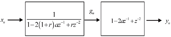
[20,21]. It is a low-complexity time domain approach which is computationally efficient compared to the frequency domain approach. In this paper, the adaptive lattice IIR notch filter structure is employed which was proposed in [22]. Adaptive lattice IIR notch filter parameters are used for the detection algorithm and the recursive least square (RLS) algorithm is used to estimate the continuous wave
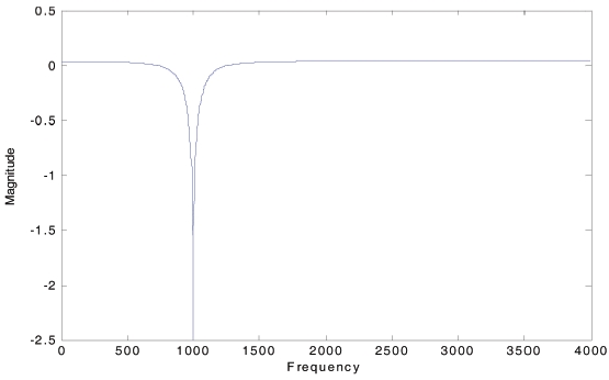
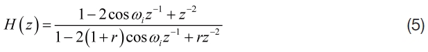
interference frequency. This filter can be used for continuous wave interference excision. Fig. 2 presents the notch filter in the frequency domain. Single-tone continuous wave interference is represented as a spectral line in the frequency domain. The notch filter can eliminate signal components in that specific frequency region by placing a notch.
The transfer function of that notch filter can be represented as Eq. (5), where
When the notch is placed at the interference signal’s frequency, the output power is minimized. Therefore, the RLS algorithm uses the notch filter output power as a cost function

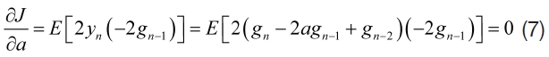
where,
and
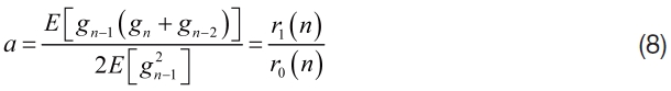
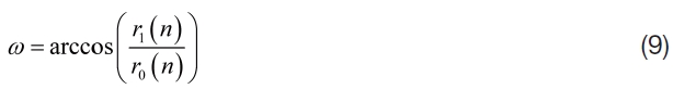
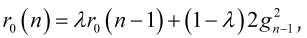
The frequency of continuous wave interference can be estimated using Eq. (9) with
3.2.2 Adaptive Lattice IIR Notch Filter Parameters for Interference Detection and Classification
The interference detection and classification algorithm utilizes

Those parameters have unique characteristics according to the type of incoming interference signal.
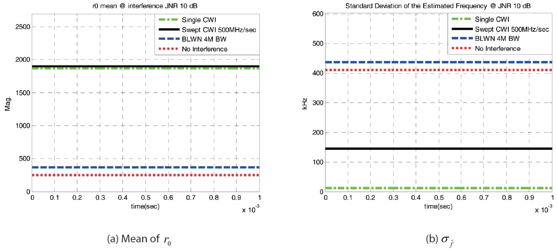
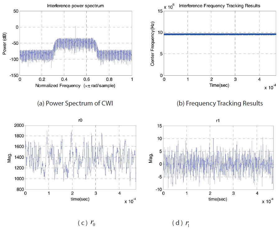
without an interference signal. In addition, the standard deviation of the estimated frequency can be used to classify the type of interferences.

of the single-tone continuous wave interference is comparably small because its frequency is fixed, while
of swept continuous wave interference becomes larger according to the range that the frequency moves during 1 ms intervals.
of the band-limited white noise is the largest because its frequency is random. Fig. 5. (b) shows the standard deviation of the frequency estimates for different interferences. In the proposed algorithm, the mean of
4. Interference Detection and Characterization Algorithm
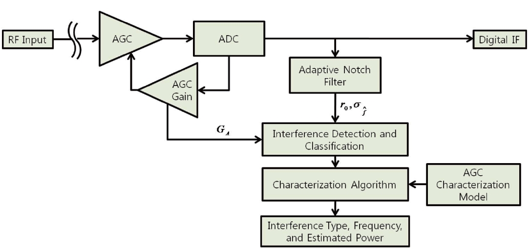
In this section, the interference detection and characterization algorithm is proposed by using AGC gain, adaptive lattice IIR notch filter parameters, and AGC characterization data. The parameter,
interference. However,
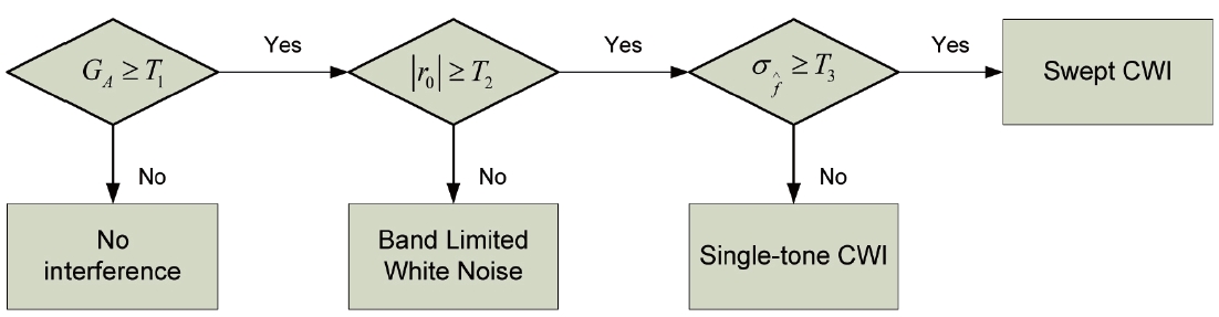
single-tone continuous wave interference, swept continuous wave interference, and band-limited white noise. Using this algorithm, more accurate power estimation is possible and this can lead to more accurate interference localization. Fig. 7 presents the flow chart of the overall algorithm in a reference GNSS receiver.
5. Performance Evaluation of the Proposed Algorithm
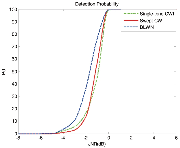
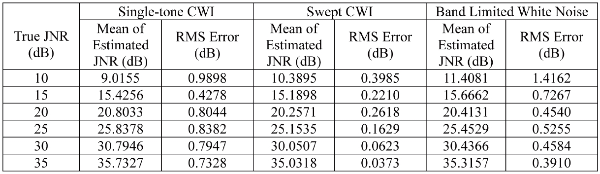
The selection of the detection threshold has a great effect on the performance of the interference detection. In this paper, the threshold is selected to detect the interference signal whose JNR is more than 0 dB, which affects the accuracy of GNSS receivers. To obtain the optimum detection parameters, the false alarm rate is fixed to 0.01, based on the Neyman-Pearson approach. To evaluate the proposed algorithm’s performance, continuous wave interferences, swept continuous wave interferences, and band-limited white noise signals are generated with power levels from JNR -15dB to JNR 35dB. The detection probability has been calculated by Monte Carlo simulations, on the basis of 300 independent runs of the detection algorithm. Fig. 8 refers to the detection probability of the single-tone continuous wave interference, swept continuous wave interference, and band limited white noise. In addition, the power estimation performance was evaluated by comparing true interference power and estimated interference power by the characterization algorithm. The mean of the estimated interference power and its RMS errors according to different power levels are outlined in Table 2. The results show that the algorithm can estimate interference power with less than Fig 8. Detection Probability of the Interference Signals 1dB RMS error.
[Table 2.] Estimated JNR and RMS Errors

Estimated JNR and RMS Errors
In this paper, the interference detection and characterization algorithm was proposed using AGC and adaptive lattice IIR notch filter parameters. AGC characterization results showed how the AGC of a reference receiver responds differently to different types of RFI. A linear model was found to be appropriate for modeling the AGC response against interference with JNR above 10 dB. Adaptive notch filter parameters were examined for interference detection and classification purpose. As a result, the mean of and the standard deviation of estimated frequency, were found to be suitable for detection and classification of single-tone continuous wave interference and swept continuous wave interference. Furthermore, in order to detect band limited white noise, the interference detection and characterization algorithm was designed by combining AGC and adaptive notch filter parameters. The simulation results demonstrated that the proposed interference detection and characterization algorithm can successfully detect and characterize three different interferences. The algorithm can detect interferences above JNR 0 dB with 100% detection probability. This algorithm can be used for intentional GNSS interference monitoring and enhancement of the interference mitigation algorithm.