The performance of a target drone depends on the kind of anti-aircraft weapons training to which it will be subjected. In the case of short range anti-aircraft gun training, the flight is conducted within a 1km range and missile-oriented training is performed over a distance of 5km. For short-range training, RC controllers are widely used. But the ground pilot’s skill has an effect on the training efficiency. In order to achieve a higher level of training, autonomous flight control systems are installed in target drones in recent years. In cases where the pilot cannot control the target drone because of limited visibility, training has been performed using autonomous UAVs. Target drones are frequently shut down during training, and so, are treated as expendables. From this view point, low cost is an important aspect in designing autonomous target drones. Therefore selecting the components of the autopilot, such as the IMU, GPS, and micro controller, is very restrictive. In this paper a MEMS rate gyro and a GPS, which are easily obtained in hobby shops, are considered for the construction of an autopilot.
The mission given to a target drone is to track a prescribed path. Various path following algorithms can be applied[1]. Usually a path following algorithm generates lateral acceleration and altitude as commands to roll attitude hold and altitude hold controller respectively. The conventional roll attitude hold and altitude hold controllers require estimations of roll and pitch angles. With IMU and GPS, an INS/GPS system [2] could be implemented to estimate the Euler angles, however those require a high-performance MEMS IMU and controller, which are beyond our consideration. An attitude reference system (ARS) [3] could be an alternative for estimating the Euler angles. In ref. [4], the Euler angles are estimated by GPS output only. These require a high performance micro-controller to run a Kalman filter. We proposed an autopilot which uses only a rate gyro and GPS, without complex algorithms such as INS/GPS or ARS.
The autopilot algorithm is designed for a fixed-wing aircraft, to be used as a target drone, which does not have a rudder due to the associated cost. The designed controller was validated through the six-degrees of freedom simulation.
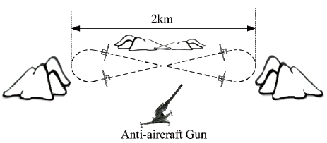
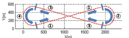
In this study, a target drone for the training of anti-aircraft guns is considered. The training is done at close range, and a target is necessary to fly on the p shown in Fig. 1. Straight flight segments should be involved to shoot the target, which is most appropriately operated within around 2km range, due to environmental conditions and/or range considerations.
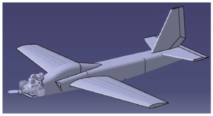
Because the target operating environment is as dangerous as a battle field, the target drone is treated as a consumable. Control surfaces of typical fixed-wing aircrafts consist of aileron, elevator and rudder. To reduce costs, the rudder is excluded in most target drones [5]. Fig. 2 shows the target drone considered and Table 1 describes the specification.
[Table 1.] Target drone specification
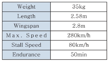
Target drone specification
The target drone is nominally operated with a speed of 250km/h at a height of 200m. A linear model was obtained for the nominal flight conditions from aerodynamic analysis [6] using DATCOM. The dynamics are described by the following state equations.
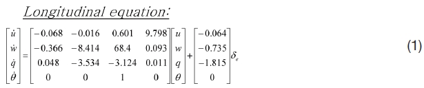
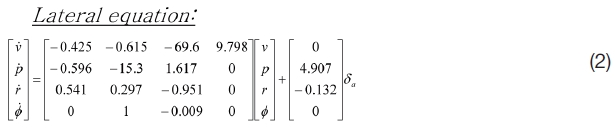
Where [
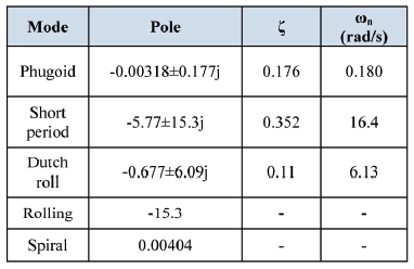
Based on the linear model, the longitudinal and lateral mode is obtained as Table 2.
[Table 2.] Target drone performance

Target drone performance
It is observed from Table 2 that dutch roll damping is poor. A yaw damper is to be adopted for conventional aircraft, but cannot be implemented for this target drone, which has no rudder.
Since low cost rate gyro, GPS and micro controllers are used to implement an autopilot, complex algorithms such as INS/GPS or ARS, which require high performance sensors and heavy computation loads, are not implemented. Therefore the Euler angles are not available. Moreover a yaw damper could not be implemented because of the rudderless configuration. So, altitude and azimuth control were reflected in these the characteristics of the target drone, but the velocity control was implemented using the typical PID controller.
Throughout this paper, the throughput rates of IMU and GPS are assumed to be 50Hz and 4Hz, respectively.
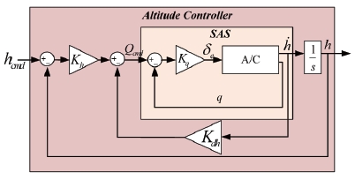
Fig. 3 shows the structure of altitude hold controller.
A longitudinal stability augmentation system (SAS) is designed to improve short period damping. The SAS gain,
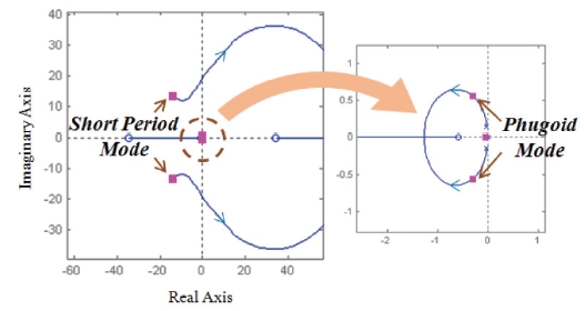
damping ratio from 0.352 to 0.7, as shown in Table 2. In a typical altitude hold controller, a pitch hold loop is included to increase the phugoid mode damping ratio. However because the pitch angle is assumed to not be available, the climb rate is fed back to obtain a reasonable damping ratio, as shown in Fig. 4.
The transfer function from
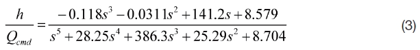
Figure 4 shows that a root locus, as
The damping of the phugoid mode is improved as
The altitude and climb rate are obtained from a GPS with a 4Hz rate which is much faster than the natural frequency of
the phugoid mode. Therefore, the time delay due to the GPS update rate does not have much effect on the performance of the altitude hold controller. Hence, the outer loop in Fig. 4 is run with a 4Hz rate, the same as the GPS output rate, while the SAS inner loop is performed with a 50Hz rate.
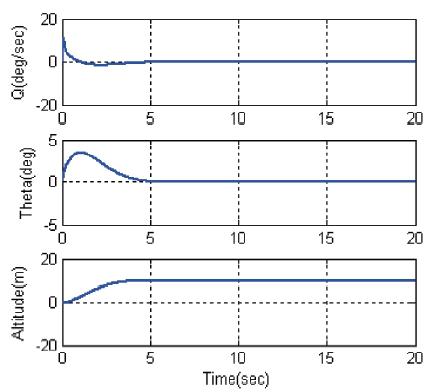
Fig. 5 shows the longitudinal responses for a step change of altitude command. The altitude controller designed results are based on a well damped step response and 3 seconds settling time.
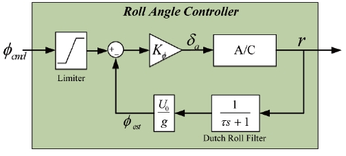
For the lateral control, roll and yaw SAS are usually implemented to have fast roll response and good yaw damping. Since the time constant of rolling mode is given as 0.07 sec in Table 2, it is fast enough, the roll SAS is not needed to be inserted into the lateral controller. Moreover the rudderless configuration prohibits the implementation of yaw SAS. Fig. 6 shows the structure of the roll angle hold controller without a roll SAS or yaw SAS. To prevent excessive roll, the roll command is limited by 45deg.
Typically, the roll angle is used for the roll hold mode, but from the assumption in section 3.1, the roll angle is not available directly from the sensor. Fig. 6 proposes to use the yaw rate instead of the roll angle to calculate feedback quantities.
In the coordinate turn, the relationship between the roll angle and the rate of azimuth angle is described as:
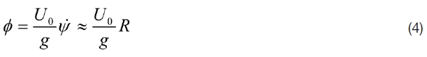
The last approximation in equation (4) holds for small roll and pitch angle. Based upon this consideration, equation (4) is used to estimate the roll angle in Fig. 6, where
Equation (4) holds for a steady state. In the beginning of a turn, the yaw rate is in the transient state and oscillates with a dutch roll frequency. Because of the rudderless configuration, dutch roll damping cannot be improved. The poor property of dutch roll generates excessive oscillation in the transient state.
To prevent feedback of oscillation, a first order low-pass filter is inserted in the yaw rate feedback loop. The cutoff frequency is chosen to be 1/5 of the dutch roll frequency. Fig. 7 shows the root locus for the roll hold controller without the low pass filter in Fig. 6.
As seen in Fig. 7, the system becomes unstable even for small
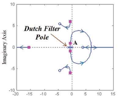
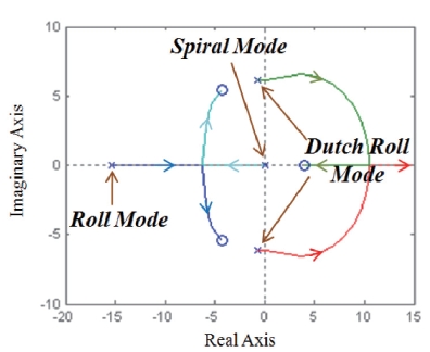
Fig. 8 shows the root locus for yaw rate with filter. Dutch roll mode moves toward anf to the left by inserting a low
pass filter, while dutch roll mode becomes unstable in Fig. 7. In Fig 8, the rectangular marker ‘■’ denotes the closed loop poles at the design point.
The location of pole A depends on the cutoff frequency of the low pass filter. Since the low pass filer is introduced to block the dutch roll oscillation, the performance of the roll hold controller is limited by dutch roll damping. Therefore the roll response of the proposed controller is slower than that of the conventional roll hold controller, which feeds back the roll angle. From the location of pole A, the bandwidth is around 1rad/sec.
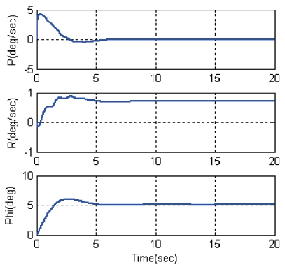
Fig. 9 shows the step response of the roll hold controller.
Yaw rate response shows that dutch roll oscillation appears as transient with a small amplitude. However dutch roll oscillation does not appear in the roll angle response. The rising time of roll angle is about 1.4sec.
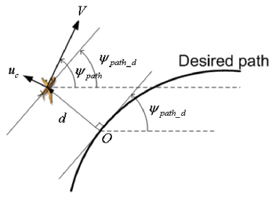
The guidance algorithm described in reference [1] is adopted here. Figure 10 shows the kinematics for the vehicle to follow the desired path. The behavior of distance error is described by
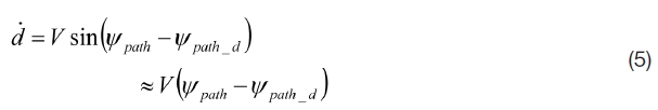
Where
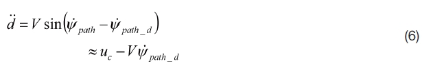
If the lateral acceleration is given as

then equation (6) becomes

where

is the calculated angular rate of the desired path, and where
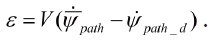
It is observed that the dynamics of distance error is expressed as a second order system, and that the bandwidth of the guidance loop is about
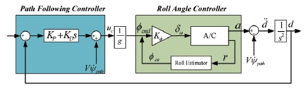
The lateral acceleration command is converted to roll angle and applied to the roll angle hold controller, as shown in Fig. 11.
The bandwidth of the roll angle hold controller should be much wider than
To evaluate the performance of the autopilot, a sixdegrees of freedom simulation was conducted for the target drone operated at 200 km/h and at 200m height in the region shown in figure 1. Measurement noise of the rate gyro is assumed to be white Gaussian with a standard deviation of 0.9deg/sec, which is typical of low cost MEMS rate gyros. The rate gyro and GPS are assumed to generate outputs of 50Hz and 4Hz respectively.
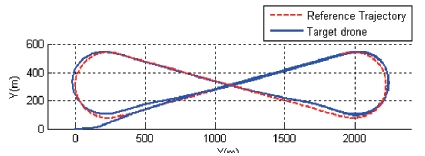
The dashed line in Fig. 12 denotes a figure-of-8 shape desired path for the target drone to follow. The desired path consists of straight lines and circular arcs, the radius of which is 250m.
Fig. 13 shows the path for the 6-DOF simulation. The aircraft starts flying toward (+)x direction at the origin, and is guided to follow the line segment ①. The distance error at the start position is large due to the initial condition, but decreases gradually as the aircraft is guided. On the early section of ②, the aircraft flies further outward than the reference circular arc, due to the slightly delayed roll response. Later, it flies inside the circular arc and follows the straight section ③ accurately.
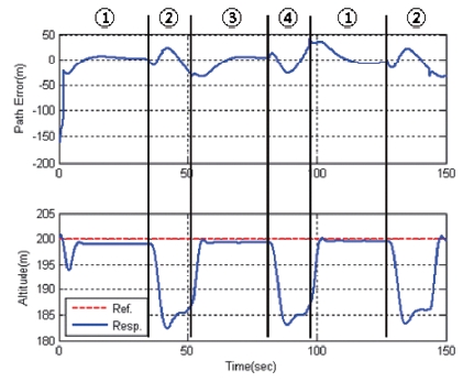
Fig. 14 shows the distance error and altitude during the operation. In turning, the segment distance error and altitude error are 35m and 18m, respectively. But in the straight segment, where the anti-aircraft gun training is performed, distance error was 7m and altitude error was 1m.
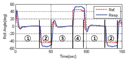
Roll command and response are shown in Fig. 15. In the straight line segment ① and ③ roll responses follow the roll command at a steady state. But in circular arc section ② and ④, the roll angle is larger than the roll command at the steady state. Equation (4) is used to estimate the roll angle hold for a coordinate turn within a small roll and pitch angle. Because the aircraft is without a rudder, it could not make coordinate turns as the roll command is large, and so, the roll angle is over estimated by equation (4). This causes the excessive roll at circular arc segments. In spite of the excessive roll, the aircraft is well guided in terms of the anti-aircraft gun training as shown in Fig. 13 and 14.
We designed an autopilot for a rudderless target drone using a low cost rate gyro, GPS, and microprocessor. The autopilot consists of altitude hold, roll hold, and a path following controller. The vertical speed output of the GPS is used to improve phugoid damping in the altitude hold controller, while the pitch rate is fed back to improve short period damping. The roll hold controller feeds back the yaw rate by assuming that the roll angle is proportional to the yaw rate at a steady state. In the transient state, at the beginning of turn, the yaw rate oscillates with dutch roll. To suppress the negative effect of the oscillation, the yaw rate is filtered out before feedback. The path following controller operates as an outer loop of the altitude and roll hold controllers.
In order to verify the performance of the autopilot, a 6-DOF simulation is conducted. A reference path is then generated based on the requirement for anti-aircraft gun training. In the turning segment, the distance error and altitude error are 35m and 18m, respectively. But in the straight segment, where the anti-aircraft gun training is performed, distance error was within 7m and altitude error was just 1m. The results imply that the proposed autopilot guides the target drone to follow a prescribed path well, in terms of anti-aircraft gun training.