Due to the rapid development of aerospace and industrial technology, aircraft development skills are also becoming more sophisticated and software dependent. So, the development of certification technology is necessary to ensure aircraft safety. Aircraft safety regulations are the minimum requirements needed to ensure the safety of the aircraft. If these regulations are not met during the certification process of aircraft development, the aircraft redesign costs will increase. Therefore, an airworthiness? design integration system that integrates aircraft safety regulations analysis and database development must be developed during the initial stages of aircraft development [1].
NASA from the United States currently uses an airworthiness?design integration system called CONDUIT (Control Designer's Unified Interface) [2]. This program integrates flight control system modeling, hardware attribute information, HQ (Handling Quality) characteristics and regulations, test data, and a variety of other information to verify the authenticity of development requirements and compliance. The CONDUIT allows the designer to retain a preferred control law structure, the system parameters to meet the handling quality requirements. Also, the CONDUIT is designed to allow for rapid problem setup and easy evaluation of complex handling quality specifications. In addition, the CONDUIT environment uses MATLAB as the arithmetic engine of the program to manage all the control system functions. All control laws are entered in MALAB's SIMULINK environment. Furthermore, the CONDUIT is also a visual environment that displays the information in plots and graphs that aid in the rapid understanding of the control system [3].
A German airline company uses MS-Excel based software called PC-Aero which utilizes an MS-Access based aircraft certification database in development. The certification database organizes and controls all the main certification tasks: regulation (FAR/JAR/CS 23/25/27/29), means of compliance, certification documents, compliance summary and the corresponding responsibilities [4].
However, the CONDUIT’s certification regulations are limited, and PC-Aero has usage constraints that are still lacking certification requirements.
Thus, as shown in Fig-1, the proposed examples are benchmarked, taking into consideration the initial design stages through all phases of aviation safety and certification
standards. An airworthiness?design integration system that integrates all of these elements must be developed to reduce design changes and trial and error.
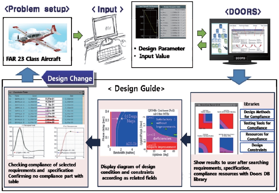
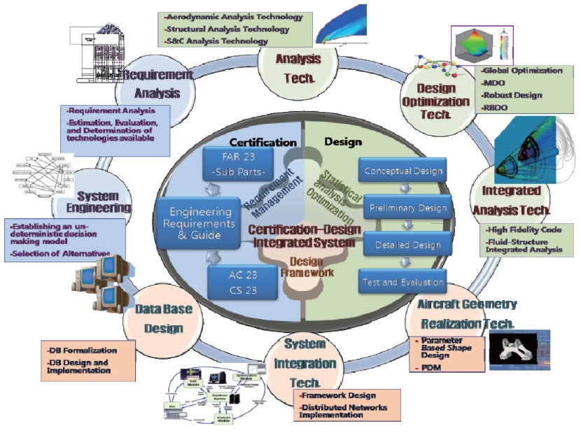
In this study, small aircraft certification requirements from the design phase will be analyzed to establish certification conditions and design guidelines for aircraft developers to follow. The documents mentioned above are established by the Database (DB) system. A database is a collection of information and is managed by a database management system (DBMS) [5]. By using DBMS, data integration can be performed between certification data and the data from detailed design process. Based on these plans, a pilot system is developed and applied to verify the system. Fig-2 shows the Airworthiness?Design Integration System concepts. The Airworthiness?Design Integration System utilizes certification techniques and design/analysis techniques to derive the optimal results. This system is established by integrating MDO (Multidisciplinary Design Optimization) techniques and an information technology framework.
2. Aircraft Airworthiness-Design Integrated System
The Airworthiness?Design Integrated System sets up the design process of small aircraft for FAR 23 class aircraft safety regulations and supports the optimal aircraft design through optimization techniques.
The process for the proposed system construction is made up of the pre-conceptual design stage, airworthiness certification analysis stage, and optimal configuration design stage.
The pre-conceptual design stage defines pre-aircraft configurations through user-requirements analysis results. The airworthiness certification analysis stage analyzes aircraft safety regulations that are related to small aircraft development and builds a database. The designed
database includes design constraints and verification requirements. The optimal configuration design stage integrates certification regulations and standard aircraft design information to optimize the system design. The airworthiness?design integration process can utilize design/ analysis/optimization organically through multidisciplinary design optimization techniques, which can maximize resources and time to establish an optimal aircraft design. The aircraft certification database will be established for applications based on FAR Part 23 (Federal aviation Regulations) [6] and the Civil Aviation Safety Authority’s KAS (Korea Airworthiness Standard) Part 23 [7].
2.1 Process of Certification Database System
The certification regulations are the related design elements, regulation database, resource management analysis system, airworthiness?design integration data technology, Web-based analysis structure, integrated product design system, and computing environment. All must be included within the infrastructure with a relevant technology level [8].
Studies are needed to improve the analysis techniques of design related resources and database establishment with regard to regulations.
The purpose of the airworthiness?design database is to properly classify and save the numerous requirement requests, design constraints, and regulations during the design phase. It must also allow for efficient data research and management.
Especially, in Fig-3, with DOORS [9], the user can trace related regulations and each user can be assigned different authorization levels for database use. Also, a large number of users utilize the database simultaneously.
2.1.1. Certification Analysis
The Airworthiness?Design Integration System can secure qualitative and quantitative airworthiness standards for aircraft design and reflect the required technical standards. In order to make this possible, related regulation content must be analyzed and a database established.
Related certification requirements from domestic aircraft technical standards Part 23, Part 33, Part 34, Part 36, the United States 14CFR23 and AC (Advisory Circular), and European CS (Certification Specifications) [10] can be analyzed to select primary certification requirements.
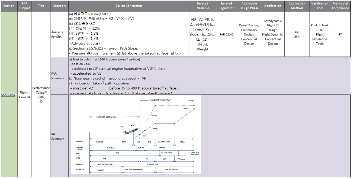
In this study, through analysis of FAR 23, KAS 23, AC 23, and CS 23, certification regulations are needed for design and were charted in the Design?Certification Related Table (DCRT) as shown in Fig-4. This table displays the association between the certification requirement and design variables as it pertains to the multidisciplinary design constraints at each phase. A designer will utilize this table to propose
applicable regulations regarding design stages, verification variables, verification methods, verification resources, and verification tools.
2.1.2 Engineering Requirements and Guide
Certification regulations and technical standards for aircraft are written in the same format as laws and regulations, and rarely provide specific values in evaluating for the development costs of small aircraft. It is also difficult for the designer to constantly refer to regulations during the development stages. Therefore, using prior authorization requirements set out by architects in aircraft design to define objectives and comply easily with regulatory requirements for certification, an Engineering Requirements and Guide can be produced.
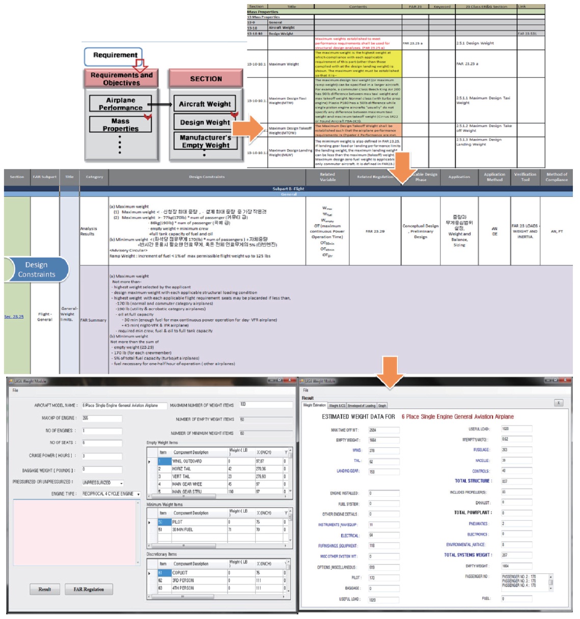
ER&G is a manual that documents certification requirements, design requirements, and airworthiness? design guidelines.
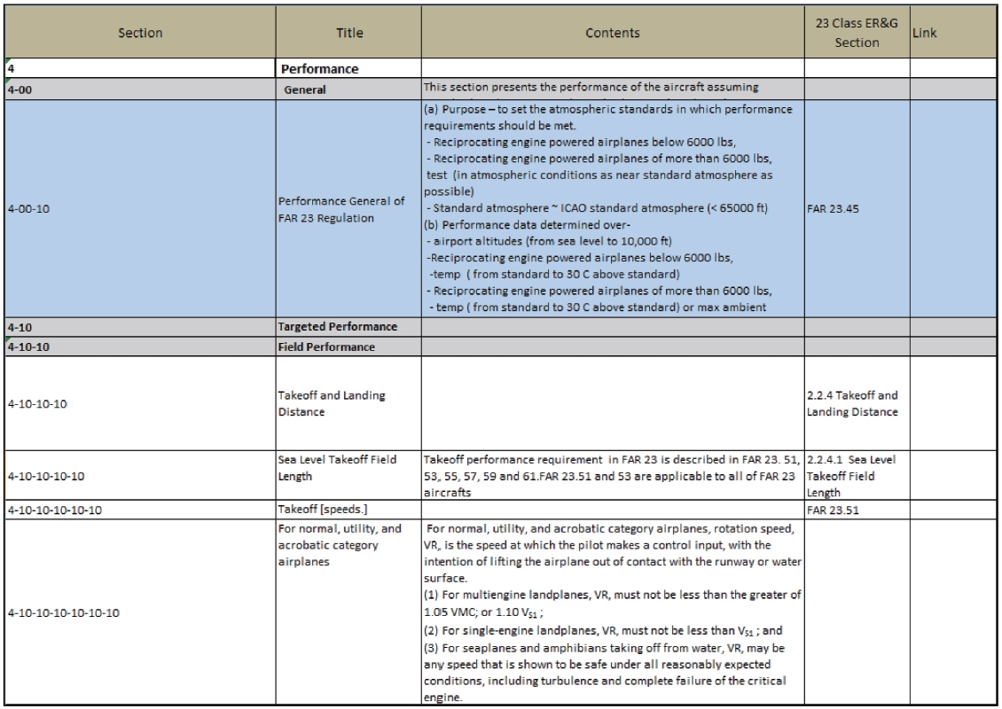
This document compares existing FAR 25 class aircraft Design Requirements & Objectives [11] and Part 25 certification. It also analyzes Part 23 certification and requests necessary information from the publishers to meet the specific conditions of FAR 23 class aircraft as shown in Fig-5. This ER&G manual is reviewed by a Canadian certification professional and built as an airworthiness? design database.
2.1.3 Airworthiness-Design Database Usage Scenario
The ER&G and Design-Certification Related Table (DCRT)
contain mission/performance/operational requirements, FAR 23 certification requirements, and any additional requirements including AC 23 and CS 23 content [12]. The two documents are connected and added to the airworthiness? design database, which makes design requirements, certification requirements, and design constraints easily accessible for aircraft developers.
The ER&G from the airworthiness?design database is analyzed systematically by aircraft technical standards, and the development of aerodynamics, propulsion, structure, control, stability, and so on are interlinked within the entire system [13,14]. In this process, as shown in Fig-6, authentication elements are classified by sector from design to verification, and analysis tools and resources are developed to validate certification requirements for compliance checking.
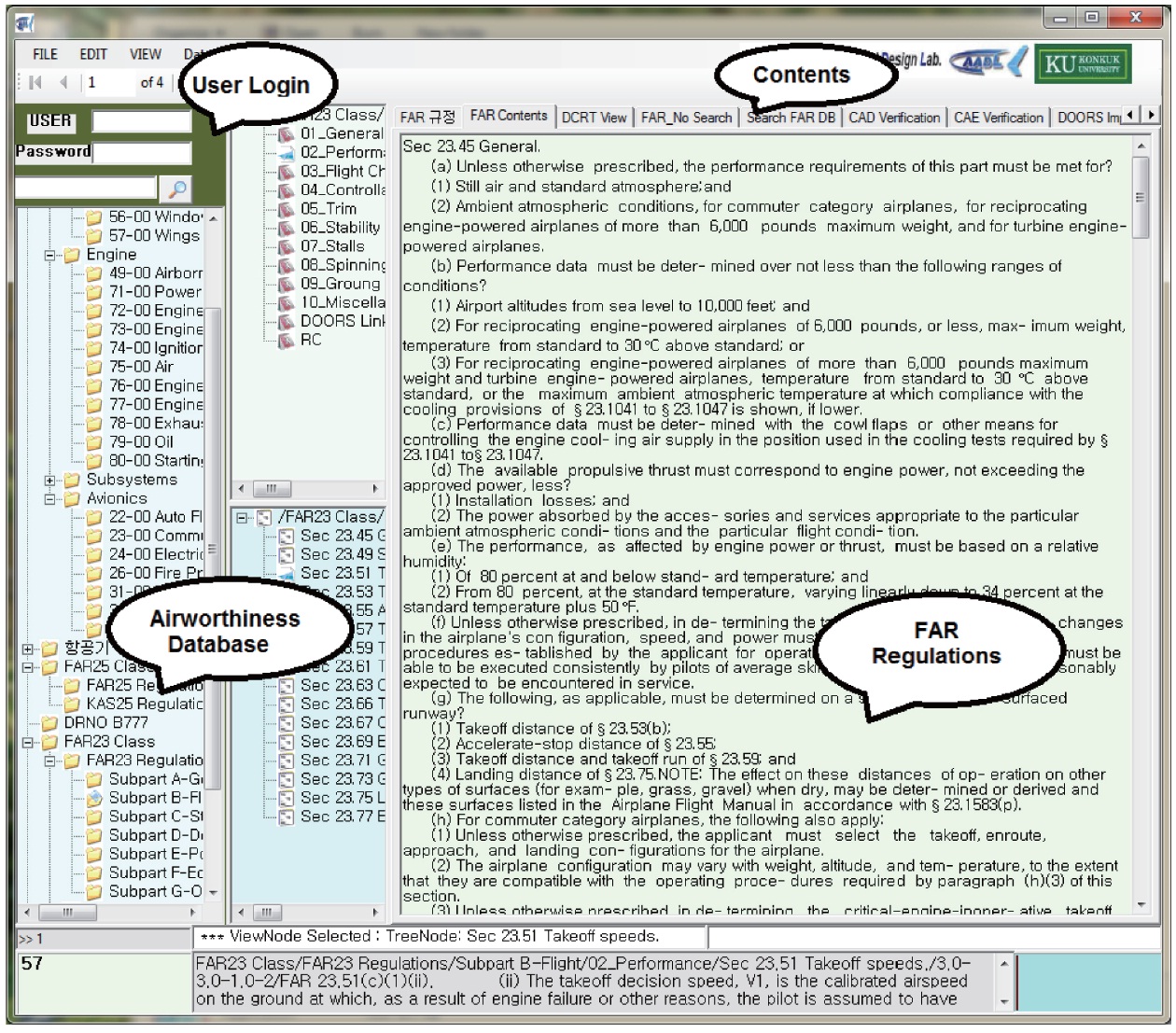
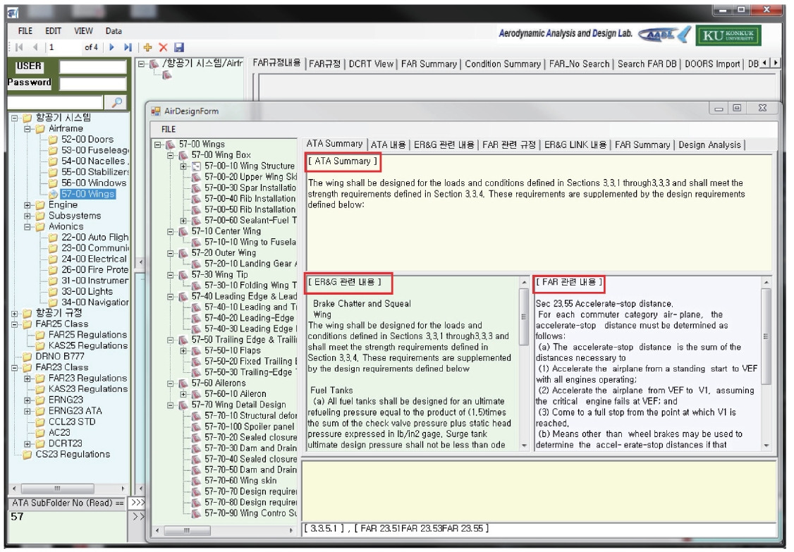
To establish an Airworthiness?Design Integrated System which uses a connection method by analyzing the certification requirements and detailed design processes, a USE CASE is developed. To verify the plausibility of the system, a pilot system is developed and adopted. Fig-7 presents an example of the system user interface. Designers gain permission to utilize the database through a login, and
are allowed to access their respective design stages according to the ATA (Air Transport Association) aircraft classification scheme.
2.2.1 Database Configuration
The system’s database is made up of the DOORS DB, which saves certification regulation data, and the SQL Server DB, which is used as the database management system for the design framework.
The SQL Server stores data from the DOORS DB and associates index information from ATA/ER&G/FAR 23/AC and other documents.
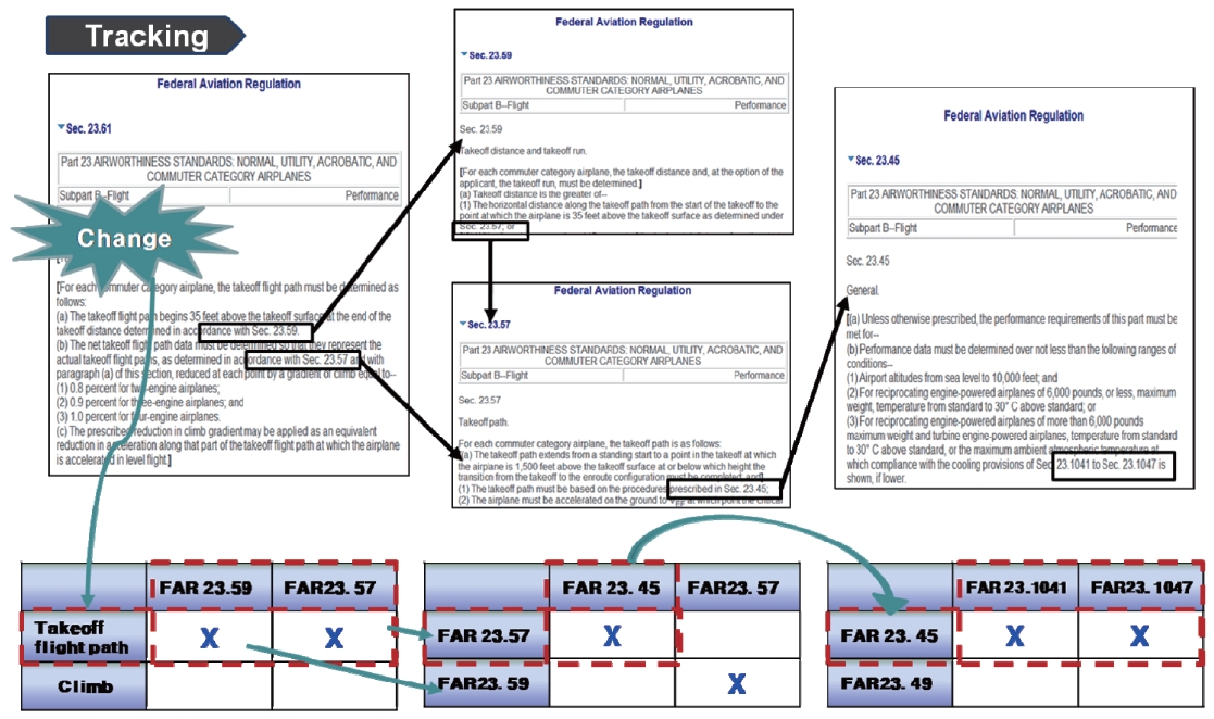
The database must be configured to allow for efficient ATA/ER&G/FAR 23/AC 23 information verification and searchability. To make this possible, the relationship between data and their structure has been studied. This made the keyword function as an index, the content readily searchable and also made related documents accessible. In addition, the ability to track revised regulations and document modifications are also provided while using the system, as shown in Fig-8.
2.2.2 CATIA Interface
As shown in Fig-9, when the desired aircraft data are entered for aircraft design parameters of the CAD Model, the API function of CATIA (VB Script) can be interconnected with CATIA knowledge.
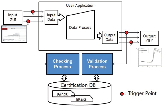
2.2.3 Checking and Validation Process
The airworthiness database and design database are connected for the verification process, which is separated into an input stage (Checking) and output stage (Validation), as shown in Fig-10. In the checking process, input variables are checked to see whether they are satisfied with the requirements for certification, verified and provide necessary information to developers. During the validation process, the proposed design variables can be used by the GUI (Graphic User Interface) to provide data for a comprehensive decision.
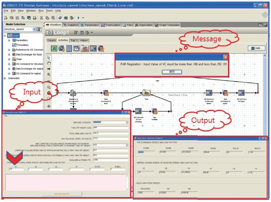
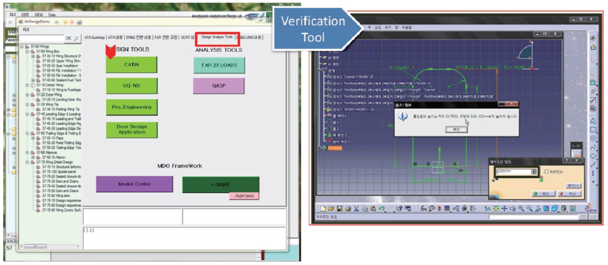
The utilization of the verification tool is implemented under commercial framework iSIGHT-FD software. Fig-11 shows the data input GUI, data output GUI and checking/ validation program connection and compares the data with the certification regulation from the database. A
designer can obtain aircraft design information without fully understanding the verification content and certification regulations.
3. Case Study of Aircraft Design Program
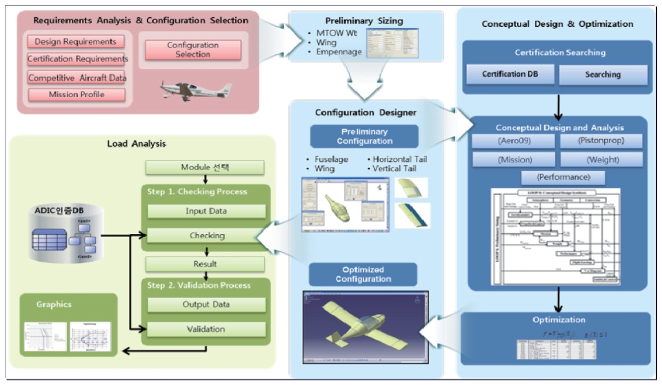
Figure 12 describes the use case scenario of the FAR- 23 class aircraft design programs with airworthiness regulations. In the first phase, designers have to define their requirements of the aircraft specifications from the design requirements program and describe the mission profile for the required aircraft. According to this user request information, the preliminary sizing program calculates aircraft data and generates draft geometry modeling with CAD commercial software (CATIA ? Computer Aided Threedimensional Interactive Application) from DASSAULT SYSTMES. The fuselage, wing, horizontal tail and vertical tail data from the configuration designer links automatically to the conceptual design module. The conceptual design module combines the aero09 program, mission program, performance program, weight program, propulsion program and the stability and control program. The conceptual design module calculates aerodynamics data of the aircraft and details aircraft design data. The certification database checks and validates the result of conceptual design data which is either satisfied or not satisfied with FAR regulations. For the optimization, genetic algorithm and sequential quadratic programming methods are used. The load analysis module provides and calculates flight loads, horizontal tail loads, control surface and system load, vertical tail surfaces, wing flaps and special devices, engine loads and ground loads data that are satisfied with FAR-23 regulations.
Preliminary sizing is developed by using simple and systematic empirical relations to work out a first layout both easily and accurately from a minimal set of user specified requirements. The preliminary sizing determines the stabilizer size and wing location which satisfy the stability requirements by using aerodynamics and stability equations. The program estimates the initial take-off weight, wing loading and thrust-to-weight ratio to design the shape of the target aircraft design.
3.2 Configuration Designer (ACD)
The aircraft configuration designer is a program based on Dassault systems CATIA CAD software and VBA scripting using the CATIA Application Programming Interface (API).
The main purpose of the ACD is to provide an easy tool for 3D configuration development and integrate it into a design analysis loop. The class function/shape function transformation (CST) and the elliptic distribution function method are used to present geometry modeling in the ACD.
3.3 Aircraft Design Synthesis Program (ADSP)
The ADSP program is developed by using the higher fidelity and detailed analysis modules to refine the first layout from the preliminary sizing. It is composed of six analysis modules which are aerodynamics, propulsion, mission, weight, stability and control and performance analysis discipline. The aerodynamic analysis, which is called AER009, is developed by using the empirical relations [15]. It is composed of drag and lift estimation. The Life coefficient results of aero009 show the better agreement with the Vortex Lattice Method [16] and Aircraft DATCOM [17] with experiment data for Navion aircraft and F/A 18-Hornet aircraft configuration. The drag coefficient is validated for a generic fighter aircraft by comparing with experiment data. The aero09 is well-developed by enhancing the strong point current aerodynamic methods to predict aerodynamic characteristics at the aircraft conceptual design stage. The aerodynamics analysis predicts aerodynamic characteristics at the aircraft conceptual design synthesis stage with various Mach numbers. The propulsion analysis module is developed for both piston and jet engine. The thrust, power available and required thrust, and power versus with speed are provided from propulsion analysis. The mission analysis estimates the burned fuel weight, takeoff weight, and the end of mission weight. The weight analysis calculates the weight components of aircraft. The stability and control analysis module provides the directional and lateral derivatives for each component such as wing, fuselage, vertical and horizontal tail. The detailed take-off and landing analysis is calculated to simulate the takeoff and landing flight condition accurately from performance analysis. Furthermore, the basic aircraft performances such as range, maximum range, endurance, maximum endurance, maximum rate of climb, and bank angle are also calculated.
3.4 Load Analysis Program (LASA)
The LASA program is developed to calculate the loads on an airplane using methods acceptable to the FAA. This program consists of 11 modules those are weight estimation, weight-CG, structural speed, mach limitation, air loads, aero coefficients, flight loads, aileron loads, flap loads, wing inertia, net loads, engine mount loads, landing loads, and
tab loads. Those data are validated with FAR-23 regulations.
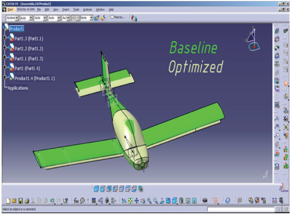
The gradient-based optimization method is applied in the preliminary sizing program to estimate the optimized values of total takeoff gross weight. The cross-plotting of sizing data is presented with the carpet plot which is based upon superimposing the takeoff weight plots from sizing plots. The ADSP program considered the multi-fidelity models technique for the multi-objective design optimization process. The multi-objective design optimization problem is to minimize the take-off gross weight and maximize the range while satisfying the design constraints. After the optimization process, the ACD program re-generates the optimized aircraft design model. Figure 13 demonstrates the baseline configuration versus optimized configuration.
In this study, aviation safety requirements are related to the development of general aviation aircraft which are analyzed and proposed design constraints and verification items. When applicable certification conditions are established, certification requirements and design guidelines are documented in the ER&G. A DOOR database utilizing, the design system, certification related resource management, and database utilization are constructed. The certification requirements and detailed design processes are associated to produce a USE CASE, and a Airworthiness?Design database system is developed to produce methods. From the initial design phase, designer can predict applicable regulations and verification methods, verification tools by using airworthiness?design database. By linking and using the airworthiness?design integration system, the user can check and validate that the analysis result data are satisfied with certification regulations.