Solar Sail propulsion has been validated in space (IKAROS, 2010) and soon several more solar-sail propelled spacecraft will be flown. Using sunlight for spacecraft propulsion is not a new idea. First proposed by Frederick Tsander and Konstantin Tsiolkovsky in the 1920’s, NASA’s Echo 1 balloon, launched in 1960, was the first spacecraft for which the effects of solar photon pressure were measured. Solar sails reflect sunlight to achieve thrust, thus eliminating the need for costly and often very-heavy fuel. Such “propellantless” propulsion will enable whole new classes of space science and exploration missions previously not considered possible due to the propulsive-intense maneuvers and operations required.
Solar sail propulsion uses sunlight to propel vehicles through space by reflecting solar photons from a large (often > 100 m per side), mirror-like sail made of a lightweight, highly reflective material. The continuous photonic pressure provides propellantless thrust to perform a wide range of advanced maneuvers, such as to hover indefinitely at points in space, or conduct orbital plane changes more efficiently than conventional chemical propulsion. Eventually, a solar sail propulsion system could propel a space vehicle to tremendous speeds―theoretically much faster than any present-day propulsion system. Since the Sun supplies the necessary propulsive energy solar sails require no onboard propellant, thereby significantly increasing useful payload mass.
Practical concepts for solar sailing have existed for approximately 100 years, beginning with Tsiolkovsky and Tsander in the 1920s. A team at JPL completed the first serious mission study in the late 1970s for a rendezvous with Halley’s Comet [1]. In the early-to-mid 2000’s, NASA’s In-Space Propulsion Technology Project made substantial progress in the development of solar sail propulsion systems. Two different 20 m solar sail systems were produced and successfully completed functional vacuum testing in the Glenn Research Center’s (GRC’s) Space Power Facility at Plum Brook Station, Ohio [2].
In the summer of 2010, the Japanese Aerospace Exploration Agency, JAXA, launched a solar sail spacecraft named the Interplanetary Kite-craft Accelerated by Radiation Of the Sun, IKAROS, in tandem with another mission to Venus. The IKAROS is the first deep-space demonstration of solar sailing [3]. While the effects of solar radiation pressure (SRP) are smaller on IKAROS when compared to other concepts for solar sails, numerous sail ‘firsts’ were achieved, including verifying SRP effects on the sail and performing in-flight guidance and navigation techniques using the solar sail.
In late 2010, NASA launched the NanoSail-D which deployed a 10 m2 sail in Earth orbit.
In 2011, NASA selected L’Garde, Inc.’s Sunjammer mission for flight validation in 2014. The Sunjammer sail will be boosted to Geostationary Transfer Orbit (GTO) as a secondary payload. Once released from the booster vehicle, Sunjammer will perform a propulsive burn and boost itself to an earth escape orbit. Upon obtaining this trajectory, the sail will be deployed.
Additional solar sail missions from the USA and Europe are being developed. Funded by The Planetary Society,
Because of the continuous force provided by solar radiation pressure on a solar sail, solar sail spacecraft can fly in non-Keplerian orbits and can continually maneuver throughout flight without the use of finite propellant.
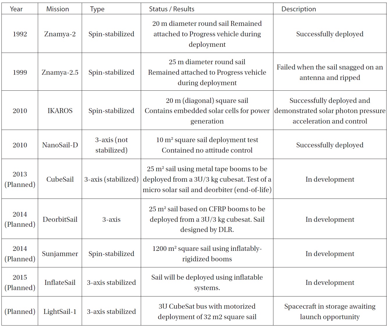
Table 1 shows a list of known solar sail demos and missions ? past and future.
2. Solar Sail Fundamentals and History
The force from solar pressure comes from the momentum transfer when solar photons (light) are reflected off the sail ? which is made of lightweight, highly reflective material. If the sail is tilted so that the force vector adds velocity to the orbital velocity of the spacecraft, then it goes faster and the orbit is enlarged. If the sail is tilted the other way so that the force vector subtracts velocity from the orbital velocity, then the spacecraft goes slower and the orbit is made smaller. Thus the direction of the solar sail spacecraft can be controlled by changing the attitude of the solar sail itself. This is how a solar sail “tacks.” Flying in Earth orbit requires frequent tacking every orbit in order to track the Sun, maneuvers not required when flying in interplanetary space. For this reason most solar sail flight applications are in interplanetary space ? hovering between the Earth and Sun for solar weather monitoring, maintaining a fixed position for Earth or other planetary observation, and enabling rendezvous and roundtrip missions to comets and asteroids.
The principle of solar sailing is succinctly stated by
ac=F/M=2Pe/c/M
where ac is the acceleration imparted to the spacecraft at 1 AU distance from the Sun, F is the force from solar photons (energy), M is the spacecraft mass. Force is the power density from solar light multiplied by the area of the sail: Pe=1370 watts/m2 x Area. From this equation the key spacecraft design objectives immediately follow: to the extent practical, keep the mass small and the area large.
That sunlight has energy and can provide a force has been known since the late 19th century, and the effect was observed as a non-gravitational force perturbing the orbits of comets. But it was Frederik Tsander and Konstantin Tsiolkovsky in the Soviet Union in the 1920s who first theorized about it providing a propulsive force for spacecraft. The first mission application seriously studied by NASA was an extremely large solar sail to enable a rendezvous with Halley’s Comet. It was an audacious idea, before its time, but the study of the mission captured both public and technical interest and led to several smaller development efforts mostly with private funding. However, by the 1990s, several national space agencies began technology programs for solar sails.
The Russian Space Agency conducted solar sail deployments in free-standing experiments observable by astronauts from their space station. The first Znamya in 1993 was successful; the second in 1999 collided with a deployed spacecraft antenna.
The first actual solar sail spacecraft built for flight was The Planetary Society’s privately funded Cosmos 1, built and
[Table 1.] Known Solar Sail Demos and Missions (Past and Future)

Known Solar Sail Demos and Missions (Past and Future)
launched in Russia. The 2005 launch failed. Meanwhile JAXA began a series of deployment test flights in 2004 leading to the successful flight of IKAROS in 2010.
NASA developed a sail vehicle on a CubeSat bus, NanoSail-D. It was not intended for actual solar sailing, but rather as a demonstration of a sail to act as an atmospheric drag device for deorbit. Its launch failed in 2008. A second attempt was made in 2010 using the flight spare. It succeeded in its orbital deployment of the sail and reentered the atmosphere several months later.
The Planetary Society took the basic NanoSail concept and developed a fully functional sailcraft with attitude control, communications, and telemetry capability called LightSail. The spacecraft is now completely assembled and sitting in storage awaiting a launch opportunity to a sufficiently high altitude -- out of the Earth’s atmosphere where solar pressure dominates.
3. Missions Enabled by Solar Sails
Now that the principles of solar sailing have been discussed, a range of potential mission applications can be investigated. Before specific mission concepts are presented, the useful domain of operation of solar sails can be outlined. Traditionally, solar sailing has been seen as an efficient means of delivering science payloads to planetary bodies, small solar system bodies, or solar polar orbit. However, solar sails can also be used to enable highly non-Keplerian orbits. These new families of orbits are extensions to the classical two and three-body problems of orbital mechanics. By exploiting the continuous low thrust available from a solar sail, exotic orbits can be found which are displaced high above the plane of the solar system, or orbits can be artificially processed to track the motion of the Earth’s magnetic tail. In the longer term, high performance solar sails can enable fast outer solar system mission to beyond the heliopause and into true interstellar space.
3.1. Near and Mid-Term Missions
Potentially the simplest application of solar sailing, with the lowest required sail acceleration, is the GeoSail mission concept. A small solar sail with a characteristic acceleration of order 0.1 mm s?2 can be used to process a long elliptical Earth-centered orbit to keep a science payload permanently within the Earth’s geomagnetic tail. The sail forces the orbit major axis to process at close to 1o per day so that the major axis of the ellipse always point along the Sun-Earth line, with the orbit apogee directed away from the Sun. Since a low mass field and particle instrument suite is typically required for geomagnetic tail missions, GeoSail can in principle be an early, low cost science application of solar sailing [7].
For a sail with a characteristic acceleration of order 0.15 mm s?2 other mission opportunities are enabled. For example, the Geostorm mission concept uses a solar sail to station a space weather payload sunwards of the classical L1 Lagrange point close to the Sun-Earth line. The sail is canted so that the artificial equilibrium position is displaced both sunwards, and slight off the Sun-Earth line to ensure that the sail is away from the solar radio disk when viewed from the Earth. Being displaced sunwards of the classical L1 point the space weather payload will detect scoronal mass ejections early and so potentially doubling the warning time of impending terrestrial space weather events [8].
Other applications of solar sails in near-Earth space include exploiting artificial equilibria high above the ecliptic plane. For a sail with a characteristic acceleration of order 0.2 mm s?2 the sail can be stationed directly over the polar axis of the Earth at the summer solstice. An imager located at such an artificial equilibrium position would provide a realtime, hemispherical view of high latitude regions and the poles for climate science, albeit with a low spatial resolution due to the large Earth-spacecraft distance of order 3 million km. Conventional spacecraft in polar orbit can provide high spatial resolution, but the temporal resolution of high latitude regions is typically poor since images from many polar passes need to be assembled to provide full coverage of the Arctic and Antarctic [9].
Solar sails can easily deliver payloads to close, polar orbits about the Sun for solar physics mission applications. Payloads can be delivered by firstly spiraling inwards to a close, circular heliocentric orbit, the radius of which is limited by the thermal tolerance of the sail film (typically of order 0.25 AU). Then, the orbit inclination of the solar sail is cranked by turning the sail and alternately directing a component of the light pressure force above and below the orbit plane every half orbit. For example, a solar sail with a high characteristic acceleration of 1 mm s?2 can deliver a payload to a solar polar orbit at 0.5 AU with a mission duration of only 2.5 years starting from an Earth escape trajectory [10].
Other inner solar system missions, such the delivery of payloads to Mercury offer quite spectacular opportunities. A ballistic transfer to Mercury using conventional chemical propulsion requires an extremely large v of order 13 km s-1, although this can be reduced using gravity assists at the expense of increased mission duration. A solar sail with a large payload mass fraction and a characteristic acceleration of 0.25 mm s-2 will deliver a payload to Mercury in only 3.5 years, while a solar sail with double the performance will require only 1.5 years. These inner solar system missions then make optimum use of solar sailing by utilizing solar light pressure to enable extremely high-energy missions [11].
For payload delivery to Mars outward spiral times tend to be somewhat longer than for ballistic transfers. However, solar sailing is not constrained by the waiting period between ballistic launch opportunities. Again, for a large characteristic acceleration of 1 mm s-2 the trip time to Mars is of order 400 days, with an additional 100 days required for capture to an initial highly elliptical orbit and the subsequent inward spiral to a low planetary orbit. While solar sails can in principle deliver a larger payload mass fraction than chemical propulsion, one-way Mars missions do not make optimum use of solar sailing since the required Δv is relatively modest.
Although one-way Mars missions do not appear attractive, two-way sample return missions do provide opportunities. For a ballistic mission, the mass delivered to Mars must include propellant for the return leg of the trip. For a solar sail mission however, propellant is only required for a lander to descend to and ascend from the Martian surface.
Other inner solar system missions for the more distant future include the use of large solar sails to reduce the total mass to low Earth orbit, and so total cost, required for the human exploration of Mars. A solar sail with a large payload mass fraction and low characteristic acceleration can deliver logistics supplies to Mars which are not time critical. For example, a large 2 x 2 km square solar sail of mass 19,200 kg can deliver a 32,000 kg payload to Mars orbit in 4.2 years from an initial Earth parking orbit. The solar sail can then return to Earth in 2 years to be loaded with another payload for delivery to Mars. This appears to be the largest solar sail which could be reasonably delivered to Earth orbit in a single launch using a large expendable vehicle.
Due to the diminished solar radiation pressure in the outer solar system, insertion of payloads into planetary orbit must be achieved using storable chemical propulsion, or aero braking if appropriate. Payloads can be delivered to Jupiter and Saturn with minimum transfer times of 2.0 and 3.3 years respectively using a solar sail with a characteristic acceleration of 1 mm s-2. After launch to an Earth escape trajectory the solar sail makes a loop through the inner solar system to accelerate onto a quasi-ballistic arc.
Again, due to the potentially unlimited Δv capability of solar sails, multiple small body rendezvous missions are possible, as are small body sample returns. For example, a sample return from comet Encke can be achieved with a mission duration of order 5 years, again using a sail with a characteristic acceleration of 1mm s-2. An Encke mission is particularly difficult since the comet has a high eccentricity, requiring significant energy for both the rendezvous and return phase. Also of interest is the possibility of a survey of multiple asteroids. This is a particularly attractive and cost effective concept since the mission is essentially open ended, allowing repeated science returns using the same suite of instruments [12]. A solar sail with autonomous on-board navigation and planning software offers exciting possibilities for such missions.
The long-range goal, some might say even the raison d’etre of solar sailing, is interstellar flight. Sailing on light is the only technology we now have that can someday enable practical interstellar flight. Sunlight will run out, even within our solar system, as an effective source of light force, but a powerful laser could focus light over interstellar distances and the resulting beamed light sail can accelerate the spacecraft to achieve interstellar missions. To achieve this goal will require a large space-based laser, presumably solar powered. Such a capability is many decades away [13].
However interstellar precursors may be possible much earlier with pure solar sail flight. Using the low mass nanospacecraft with larger sail areas and advanced sail film material, missions that fly in toward the Sun with a very low perihelion can achieve very high escape velocities from the solar system. Achieving missions with extra-solar system destinations hundreds of AU from the Sun may be possible in less than 50 years [14].
4. Technology Status - Small Solar Sails
With the rapid development and utilization of very small spacecraft such as cubesats, the need for innovative, lightweight propulsion systems with very high ΔV capabilities has increased commensurately. Solar sail propulsion offers these small spacecraft increased capability, allowing propulsiveintense maneuvers to be accomplished inexpensively and with minimal accommodation requirements.
NanoSail-D is a 3U cubesat sailcraft that was successfully launched on the FastSat-1 mission on November 19, 2010 with deployment on January 17, 2011 [15]. The flight phase of the mission successfully demonstrated a deorbit capability that could potentially be used to bring down decommissioned satellites and space debris by re-entering and totally burning up in the Earth's atmosphere. The stowed sails were 2.5 u CP-1 material with an area of approximately 10 m2 and utilized 2.5 m Triangular Rollable And Collapsible (TRAC) booms. NanoSail-D re-entered the Earth’s atmosphere on September 17, 2011, after spending 240 days in space.
CubeSail is a nano-solar sail mission based on the 3U CubeSat standard, which is currently being designed and built at the Surrey Space Centre, University of Surrey and funded by Astrium. CubeSail will have a total mass of around 3 kg and will deploy a 5 x 5 m sail in low Earth orbit. The primary aim of the mission is to demonstrate the concept of solar sailing and end-of-life deorbiting using the sail membrane as a dragsail. The spacecraft will have a compact 3-axis stabilized attitude control system, which uses three magnetic torquers aligned with the spacecraft principle axis as well as a novel two-dimensional translation stage separating the spacecraft bus from the sail.
The CubeSail will demonstrate solar sailing by changing the inclination of its orbit. To keep the effects of drag low, the CubeSail will face towards the normal of the orbital plane, flying on its edge into the velocity vector. The initial orbit is a ~700 km sun-synchronous orbit. The inclination stays roughly the same throughout the 360 days of the simulation for the CubeSat, while the CubeSail achieves a 2o change in inclination. At the end of its lifetime the CubeSail will change orientation and point its sail along the velocity vector. The increased cross sectional area will cause rapid descent. CubeSail could therefore be used as a deorbiting device and when attached to any spacecraft [5]. It will be able to affect the ballistic coefficient of the spacecraft after deployment, causing rapid deorbiting.
DeorbitSail is a cubesat mission to demonstrate inspace deployment of a large thin membrane sail and to demonstrate deorbiting. The sail will be deployed from a 10 x 10 x 30 cm cubesat platform which will be 3-axis controlled.
The uncontrolled growth of the space debris population has to be avoided in order to enable safe operations in space for the future. Space system operators need to take measures to conserve a space debris environment with tolerable risk levels, particularly in Low Earth Orbit (LEO) altitude regions.
DeorbitSail will demonstrate the use of sail deployment technology for use as a deorbiting system. The effectiveness of such deorbiting device is predicted to be high at altitudes lower than 1000 km for mini-satellites (20 to 500 kg) if deorbiting time constraints of 25 years are being considered. The same design will also be capable of using solar radiation pressure as a deorbiting force above 1000 km in altitude.
InflateSail will be stored in a 3U cubesat structure and the launch costs will be freely covered as part of the space technology flight demonstrator mission QB50. It is to demonstrate rigidization of an inflatable structure in orbit. InflateSail is a circular sail supported by an inflatable structure that can potentially be used as a drag brake for deorbiting, as a solar sail propulsion system, as a large reflector/antenna, or as a Sun shield. It is to have a total sail area of approximately 10 m2 with a 3 m diameter inflatable torus frame that stretches the sail film by a series of equidistant cords. The torus is to be suspended from the satellite bus by three inflatable booms.
LightSail-1 is being developed by the Planetary Society using entirely private funding. The 3-axis stabilized spacecraft will have a total area of 32 m2 and be deployed from a cubesat. The LightSail is designed to deploy at an altitude of 800 km and will demonstrate controlled sailing after deployment.
The LightSail spacecraft is complete and now in storage awaiting a launch.
5. Technology Status - Large Solar Sails
To implement many of the ambitious solar sailing missions described in Section 3 will require very large sails on the order of a few tenths to a half of a kilometer in diameter. Sails in this size class are being developed and tested in Europe, Japan, and the United States.
IKAROS launched by JAXA on May 21, 2010. IKAROS successfully deployed on June 9, 2010. In December 2010 IKAROS successfully passed by Venus showing an accumulated acceleration of 100 m/s [3]. The spacecraft weighs approximately 300 kg and consists of four 7.5 u sail quadrants which deploy using centrifugal force to a diameter of 20 m [16]. Several unique features of IKAROS include:
Thin film solar cells attached directly to certain areas of the membrane. They generate almost 500W. The area ratio is 5%.
Steering device: Variable reflectance elements are loaded near the tips of the membrane. They can be used to control the spin direction and provide attitude control.
The L’Garde Sunjammer mission will see the development and flight of a 1200 m2 solar sail with an anticipated launch date in 2014. The preliminary design calls for the sail to be boosted to Geostationary Transfer Orbit (GTO) as a secondary payload. Once Sunjammer (the sailcraft is named after a short story by Arthur C. Clarke) is released from the booster vehicle, it will perform a propulsive burn and boost itself to an earth escape orbit. Upon reaching this trajectory, the sail will be deployed and the demonstration mission will begin.
The Sunjammer design relies on L’Garde inflatable rigidizable technology in the sail structure. The sail structure consists of four conically-stowed, inflatably-deployed, coldrigidized booms. These four booms are connected at the center of the sail area to the sailcraft bus. Less than 2 days after launch, the solar sail will be deployed to full size and separated from the carrier. Within 6 days of launch the sail will be calibrated and trimmed. For the next 30 days the sail will navigate to demonstrate and fulfill navigation requirements. Sunjammer will fly the sail near L1 and finally to a sub-L1 location. Along the way, an onboard magnetometer will be measuring magnetic field and comparing the results with NOAA’s Advanced Composition Explorer. It is hoped that these measurements will foster infusion of this technology into the space weather monitoring community.
5.3. Gossamer Spacecraft Initiative
The German space agency DLR has an active program of solar sail development through the Gossamer Spacecraft Initiative (GSI). The GSI has three parts with Gossamer-1 a small 5 x 5 m in-orbit deployment test, Gossamer-2 a 20 x 20 m in-orbit deployment test and Gossamer-3 a full solar sail demonstration of a 50 x 50 m sail. At the completion of the roadmap, the solar sail assembly would then be available for future science and commercial mission applications. Gossamer-1 will use DLR composite boom technology with the booms wound onto a spool and deployed by a drive motor. The sail film will use conventional 7.5 mm Kapton. Goassmer-3 is expected to deliver a characteristic acceleration of greater than 0.1 mm s-2 and will spiral to Earth escape after deployment.
Solar sail technology is advancing rapidly around the world. The Japanese IKAROS mission confirmed via flight testing in deep space that large solar sail technology is viable for space flight operations and NanoSail-D performed a similar function for small spacecraft. Many important applications of solar sails have been identified as useful to the international science community and there is a growing interest in using solar sails to implement them.