An optimum heat sink for a 30 W chip on board (COB) LED down-light is designed, fabricated, and characterized. By using the SolidWorks Flow simulator and thermal analysis software, the thermal characteristics of the optimum heat sink is analyzed. Four different types of heat sink are simulated and an optimum structure of the heat sink is found. The simulated temperature of the heat sink when operating the LED down-light is 55.9℃, which is only a difference of 2℃ from the measured temperature. In order to reduce the temperature further, a copper spreader is introduced to the heat sink. The temperature of the heat sink with the copper spreader is 3℃ lower than without the copper spreader.
The LED light bulb is a low power and highly efficient light source. It is superior to the conventional light bulb or florescent light in terms of energy efficiency, intensity of illumination, lifetime, and durability. Due to these advantages, the conventional light bulbs are gradually replaced by LED light bulbs [1].
However, the LED light bulb is relatively expensive and may have problems such as transition of color temperature, degradation of light efficiency, and short lifetime due to the increase of junction temperature. The researches of packaging and circuit technology for LED light bulbs are prevailing and now people are focusing on resolving the problems mentioned previously due to the junction temperature [2].
As the size of the LED component increases, the light extraction efficiency degrades, which tarnishes the greatest advantage of the LED light source. Furthermore, the wide area of the LED component makes not only light emission efficiency but also heat radiation worse.
When the size of the LED component increases, the injection of the operating current increases and internal and external quantum efficiency degrades, which result in decreasing the amount of light and shortening its lifetime.
In addition, decreasing luminous flux at a certain level of temperature results in changing the color temperature of white light that is combined with yellow phosphor. Therefore, design of the highly efficient heat radiation structure with a small size of the LED component is very important in LED light bulbs [3]. The heat radiation problem in LED light bulbs is caused by the fact that the supplied power of 70-80% is transformed to heat energy. In order to resolve the heat radiation problem in LED light bulbs, the basic solution is the optimum design of the heat sink fin structure. In the efforts of reducing thermal resistance at the LED package level, researches of chip on board (COB) technology or high thermal conductive materials are widely conducted [4].
However, thermal design in LED light bulb industry is performed without thermal simulation for a heat sink. They usually use a conventionally manufactured heat sink for the LED light bulb. They only analyze the thermal characteristics of the LED light bulb by measuring the temperature of LED light bulbs and iterate the process until an optimum design is found. This iteration is inefficient in terms of cost and time.
In this paper, an optimum design of a heat sink for a 30 W COB LED down-light is suggested. The thermal-flow phenomenon of the heat sink is analyzed by simulations and the thermal characteristics of the optimally designed heat sink are evaluated by measurements to propose an efficient thermal design method.
2. DESIGN OF LED HEAT RADIATION
2.1 Theory of LED heat radiation design
Heat transfer in a COB LED package subsequently occurs from chip to package, from package to heat sink, and from heat sink to the external environment. In a solid medium, heat transfer occurs from a hot area to a cold area of the medium when the temperature gradient exists in the medium. Besides, in microscopic view, heat transfer results from the interactions between atoms or molecules in the material. The interactions include the vibration of atom lattice or movement of free electrons. The thermal flow rate depends on the heat transfer coefficient of material, denoted by k, and is applied by Fourier’s Law of heat transfer theorem given by the following equation [5].

Eq. (1) is the heat transfer equation in which A is the cross sectional area, ΔT is the amount of temperature variation, x is the length, and k is thermal conductivity, respectively.
Figure 1 is a graph of the thermal-flow phenomenon with respect to temperature variation vs. distance. Figure 1 shows that temperature is inversely proportional to the distance. A heat sink transfers heat through fins and by natural convection, therefore it is an efficient method for thermal design. As the convection area (
The heat transfer equation regarding the heat sink is given in Eq. (2) as follows.

If there are fins in heat sink, fin availability should be large to increase efficiency of the heat sink. Fin availability (
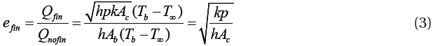
In order to increase fin availability (
2.2 Specifications of the COB LED package
A 30 W COB LED package used in this work is manufactured by CITILED Company. The part number of the COB LED package is CLL050 and the detail specifications and its pictures are shown in Table 1 and Fig. 2, respectively.
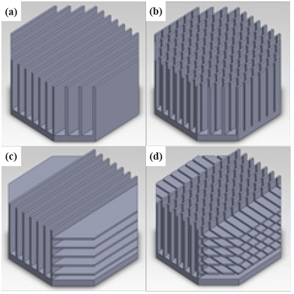
Four different types of fin shape and structure are designed. Each design has a total surface area of 181 m2 with the tolerance
[Table 1.] Detail specifications of the 30 W COB LED package.

Detail specifications of the 30 W COB LED package.
of ±2%. The total surface area is initially calculated by Heatsinkdesigner, a heat sink design simulator. The total surface area is obtained to be 181 m2 for the best heat transfer characteristic. Figure 3 shows the four different types of the 181 m2 heat sink
[Table 2.] Material properties used in SolidWorks flow simulation.
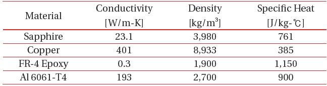
Material properties used in SolidWorks flow simulation.
structure. The dimension of the four heat sinks is 120 mm × 120 mm × 62 mm. The thickness of the base and fin is 7 mm and 2.8 mm, respectively. The heat sink is made out of aluminum.
3. EXPERIMENTAL RESULTS AND DISCUSSIONS
3.1 Heat transfer simulation method
The thermal analysis for the four different types of heat sink is performed with SolidWorks Flow Simulation, a thermal analysis simulator. The material properties for the thermal analysis are given in Table 2. In the simulator, a closed space volume of 1 m3 is established to enclose the heat sink in free space. The space has environmental properties as follows: the temperature of 25 ℃ and heat transfer coefficient of 5 W/m℃. In order to improve the convergence of the simulation, more than 700 thousand meshes are created.
3.2 Simulation results and discussions
Temperature characteristics for the four different types of heat sink is summarized in Table 3. As can be seen, Type A has the lowest temperature of 55.9℃. Figure 4 shows the temperature contour of the four different types of heat sink.
Overall, heat flow can be characterized as follows: cold air flows from the outer edge of the heat sink to the center of the heat sink and the cold air flowing inside the heat sink is heated up by the hot heat sink. The density of the heated air becomes low and the heated air rises above the heat sink. This type of heat flow is generally known as the “chimney pattern” [8].
In case of Type C and D, the horizontally protruded fin prevents hot air inside the heat sink from rising above the heat sink. This causes heat to concentrate on the center of the heat sink and the overall temperature of the heat sink becomes high. In
[Table 3.] Simulation temperatures of the four different types of heat sink.
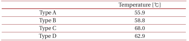
Simulation temperatures of the four different types of heat sink.
case of Type B and D, the density of the fin is too high to increase the heat capacity. This results in the rising temperature at the center of the heat sink and heat conduction to the outer edge of the heat sink is low. In comparison of Type C and D, the fin density of Type D is higher than that of Type C, which can make the hot air rise above the heat sink without disturbance. Therefore, Type D has a lower temperature than Type C.
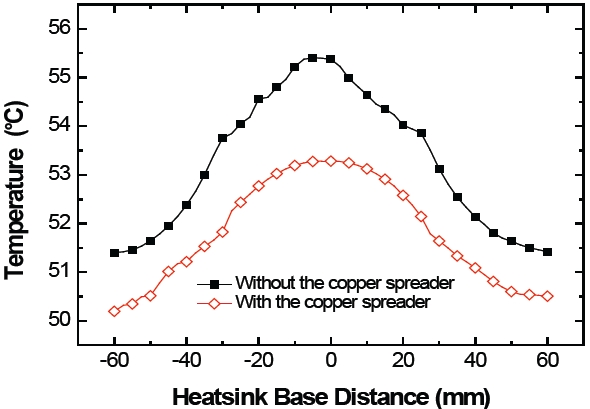
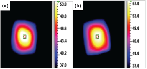
Even in Type A, heat from the COB LED package concentrates on the center of the heat sink due to the small area of the printed circuit board in the COB LED package. In order to relieve this concentration of heat to the center of the heat sink, the “copper spreader” is attached to the heat sink of Type A. This copper spreader makes heat spreading from the center of the heat sink to the outer edge of heat sink. The temperature contour of the heat sink with and without the copper spreader is shown in Fig. 5 (a) and (b), respectively.
Figure 6 presents the temperature characteristics with respect to the relative distance from the center of the heat sink. At the center of the heat sink, the temperature of the heat sink with the copper spreader is 53.7℃, which is 3℃ lower than without the copper spreader. It can also be observed in Fig. 6 that the temperature deviation between the center of the heat sink and the outer edge of the heat sink is smaller when the copper spreader is attached.
Since heat spreading is facilitated by attaching the copper
spreader from the center of the heat sink to the outer fin, the temperature becomes lower in the simulation results.
3.3 Measurements of thermal characteristic
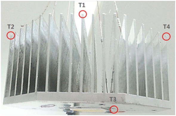
A closed space of 1 m3 is prepared to measure the thermal characteristics of the COB LED package with the optimized heat sink designed by the thermal analysis simulator. The heat sink on which the COB LED package is attached is placed at the center of the closed 1 m3 space. In the 1 m3 space, no internal air flow exists and the internal temperature is kept at 25℃. The temperature of the heat sink on which the COB LED package is attached is measured by the IR1001E infra-red thermogram camera after turning on the LED package and one hour aging. In addition to the measurement with the thermogram camera, the temperatures of the four points of the heat sink are measured every 5 seconds for one hour using the thermo couples with SE309 software developed by the Omega Company.
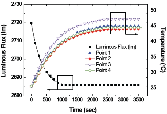
In order to evaluate the light characteristic of the COB LED package, the lumen maintenance factor with respect to the temperature variation of the COB LED package is measured every 5 seconds for one hour using an integrating sphere system, PMS- 50 manufactured by the EVERFINE Company. Figure 7 depicts the location of the four thermo couples on the heat sink.
3.4 Evaluation of thermal characteristics and discussions
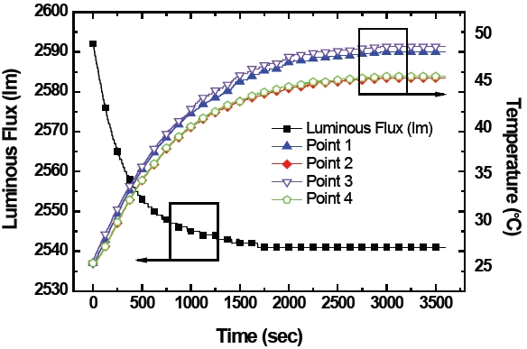
Figure 8 shows the temperature and lumen maintenance fac-
tor with respect to time when using the heat sink without the copper spreader. The temperature at the center of the heat sink is the highest, which corresponds to the simulation results. It can also be observed that the heat transfer from the center to the outer edge of the heat sink is poor.
Figure 9 illustrates the temperature and lumen maintenance factor with respect to time when using the heat sink with the copper spreader. As expected, the temperature at the center of the heat sink is the highest. The heat transfer from the center to the outer edge of the heat sink, however, is very good in comparison with the heat sink without the copper spreader. It can be observed that the temperature of the fin around the center is comparable to the temperature of the fin around the outer edge of the heat sink. Also, the lumen maintenance factor quickly becomes stable and the initial light flux is high.
The temperature characteristics with and without the copper spreader measured by the thermogram camera are shown in Fig. 10. With the copper spreader, the temperature is 54.3℃ and without the copper spreader, the temperature is 57.4℃, which is very close to the simulation results with ±2℃ error.
We have developed and characterized an optimum heat sink for a 30 W chip on board (COB) LED down-light. By using a Heatsink designer, the optimum total surface area of a heat sink for the 30 W COB LED down-light is found to be 181 m2. From four different types of heat sink design, an optimum structure, type A in this work, can be found. Since the center of the heat sink is very hot due to the package structure of the COB LED, a copper spreader is introduced to spread heat from the center to the outer edge of the heat sink. When applying the copper spreader, the temperature of the heat sink is approximately 3℃ lower than without the copper spreader. The simulation and measured results are very close to each other and within ±2℃ error. The effectiveness of the simulations can be observed. In order to improve the reliability of the heat radiation design, research should be in progress and an active heat radiation structure for the LED light system needs to be completed.