검색 전체 메뉴
PDF
맨 위로
OA 학술지
Error Performance of Spatial-temporal Combining-based Spatial Multiplexing UWB Systems Using Transmit Antenna Selection
  • 비영리 CC BY-NC
  • 비영리 CC BY-NC
ABSTRACT
Error Performance of Spatial-temporal Combining-based Spatial Multiplexing UWB Systems Using Transmit Antenna Selection
KEYWORD
Ultra-wideband (UWB) , Spatial multiplexing , QR decomposition , ZF detector , Rake combiner , Spatialtemporal combining
  • I. INTRODUCTION

    Ultra-wideband (UWB) radio technology has attracted tremendous interest for applications requiring high-data rate communications over short ranges. UWB systems trying for higher data rates and higher quality of communications can employ multiple input multiple output (MIMO) techniques [1]. However, the implementation of MIMO suffers the main disadvantage of increasing hardware costs due to the radio frequency (RF) chains and analog-to-digital converters needed. If we use an antenna selection technique, this handicap can be reduced [2-5]. In [6], the transmit antenna selection problem in spatial multiplexing (SM) UWB MIMO systems with zero-forcing (ZF) detectors followed by Rake combiners (called a ZF-Rake), whose structure has been analytically examined in [7], has been discussed. In [8], the 2-dimensional Rake architecture in the space and time domain followed by a ZF detector (called a 2Rake-ZF receiver) has been analytically examined to show that it can improve the error performance of the ZF-Rake receiver.

    In this paper, a transmit antenna selection algorithm is applied to the spatial-temporal Rake combining-based SM UWB systems proposed in [8]. The transmit antenna selection criterion employed for selecting a subset of the transmit antennas is based on the largest minimum postprocessing signal-to-noise ratio (SNR) obtained on the basis of QR decomposition. Simulation results will show that the transmit antenna selection algorithm can significantly enhance the BER performance of SM UWB systems with the 2Rake-ZF receiver on a log-normal multipath fading channel. It will also be found that when the transmit antenna selection scheme is used in the SM UWB systems, the 2Rake-ZF receiver outperforms the ZF-Rake receiver and also achieves the diversity order of the full complexity antenna system.

    II. SPATIAL-TEMPORAL COMBINING SYSTEMS USING TRANSMIT ANTENNA SELECTION

    To examine the antenna diversity gain through transmit antenna selection, the spatial-temporal combining-based SM UWB systems presented in [8] with NT transmit antennas, NR receive antennas, and a 1: NS ( NT > NS, NRNS ) multiplexer are considered. The subset selection of NS transmit antennas among the set of all possible

    image

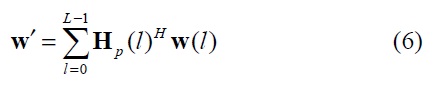
    subsets of transmit antennas is carried out by a transmit antenna selection algorithm on the receiver. The receiver feeds back to the transmitter the determined subset. The input data to the multiplexer are serial-to-parallel converted into NS data streams and then sent to NS transmit antennas for simultaneous transmission, which are modulated with the pulse-amplitude of a UWB pulse with short-duration. The assumption that the pulse repetition interval is adequately larger than the channel delay spread can enable avoiding severe intersymbol interference. It is also assumed that the transmitted signals from the chosen transmit antennas pass through a multipath fading channel with log-normal distribution and the channel coefficients of the L resolvable paths are perfectly known to the receiver.

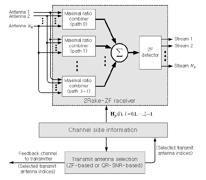
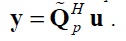
    After the received signal at each receive antenna goes through a correlator, the resulting correlator outputs are spatially and temporally combined by the 2-dimensional Rake receiver over each bit interval, as shown in Fig. 1. Then the discrete-time spatial signal vector, u =

    image

    , is written as [8],
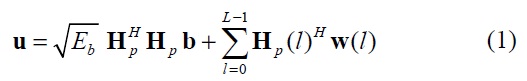
    image

    where Eb is the average bit energy,

    image

    with the information bit from the nth data stream denoted by

    bn ∈ {+1, -1} , n = 1,2, NS and w(l) = [w1(l) w2(l) wNR(l) ]T with wm (l) , m = 1,2, NR, being the zero-mean white Gaussian noise component of a variance of N0 / 2 at the m-th receive antenna. Here, Hp is a channel matrix corresponding to a subset of best antennas selected from the larger set of available antennas and given by

    image
    image
    image

    where hmn (l) is the channel fading coefficient of the l-th resolvable path from the nth transmit antenna to the m-th receive antenna and can be modeled as hmn (l) = ζ mn (l)gmn (l) where gmn (l) is the log-normal fading magnitude and ζ mn ( l ) ∈{ +1,-1} indicates the phase inversion with equal probability.

    After the outputs of the spatial-temporal 2-dimensional Rake combiners are performed by a ZF detector,

    image

    to spatially decorrelate
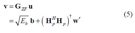
 NS data streams, the decision variable is written as,

    image

    where (□) denotes the pseudoinverse and

    image

    Note that this work focuses on using ZF detection even if other SM MIMO detection techniques could be considered.

    III. TRANSMIT ANTENNA SELECTION FOR SPATIAL-TEMPORAL COMBINING SYSTEMS

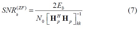
    From expression (5), the SNR of the ZF detector output signal on the k-th stream in the 2Rake-ZF receiver using the 2-dimensional combining method in the space and time domain described in Section II can be described as,

    image

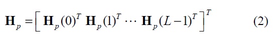
    In order to derive the post-processing SNR expression in the 2Rake-ZF receiver, the channel matrix,

    image
    image

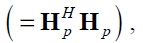
    obtained after spatial-temporal combining is considered instead of using only Hp . The NS × NS modified channel matrix

    image

    determined by the transmit antenna selection process can be factorized by QR decomposition
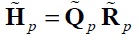
    image

    with unitary NS × NS matrix

    image

    and the upper triangular NS × NS matrix

    image

    . The left side of the NS × 1 received signal vector u of the Eq. (1) is multiplied by the Hermitian matrix of

    image

    Then the received signal vector is modified to

    image

    The postdetection SNR of layer
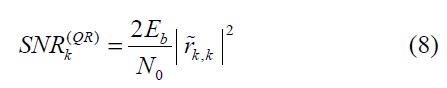
 k after spatial and temporal combining can then be given by

    image

    where

    image

    is the k-th diagonal element of the upper triangular matrix

    image

    . The elements of

    image

    can be calculated by the well-known QR factorization algorithm based on a modified Gram-Schmidt method.

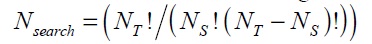
    An antenna subset selection is determined by the maximum minimum post-detection SNR. It searches for a transmit antenna subset with the maximum value among Nsearch minimum post-detection SNRs computed for the set of all possible transmit antennas using the expressions (7) and (8). The selection criteria given by the expressions (7) and (8) are called a ZF-based selection criterion (ZF-SC) and a QR-SNR-based selection criterion (QR-SNR-SC), respectively. For every subset of transmit antennas, compute the corresponding

    image

    and

    image

    , respectively, which are defined as minimums of

    image

    , and

    image

    , k = 1,2, … , NS, using the SNR expressions (7) and (8). Then select the subsets with the maximum

    image

    and

    image

    values. Finally, the 2Rake-ZF receiver is operated for signal detection using the determined antenna subset. Thus the 2Rake-ZF receivers based on ZF-SC and QRSNR- SC are called ZF-2Rake-ZF and QR-SNR-2Rake-ZF, respectively.

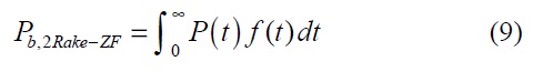
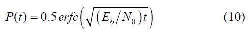
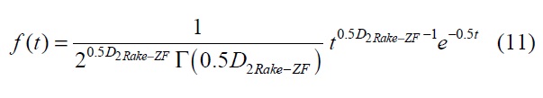
    Even if the communication system with antenna selection considered in [2] and [4] is not a SM UWB one with a lognormal fading distribution, the antenna selection has been shown to maintain the same diversity advantage as the full complexity antenna system without antenna selection. To observe the antenna diversity gain of the ZF-2Rake-ZF and QR-SNR-2Rake-ZF through antenna selection, this work considers the average BER performance of the 2Rake-ZF UWB system with no antenna selection in a log-normal fading channel examined in [8], which is given by
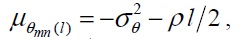
    image

    where,

    image
    image

    Here, D2Rake-ZF (= LNRNT + 1) indicates the diversity order of the SM UWB system based on the 2Rake-ZF receiver and Γ(?) is the gamma function.

    IV. SIMULATION RESULTS

    The average power of the path with index l =0 is assumed to be unity. The log-normal fading amplitude gmn (l) can be represented by gmn (l) = eθmn(l) , where θ mn (l) is a Gaussian random variable with mean μ θmn(l) and variance

    image

    (independent of l , m , and n ). It is assumed that the standard deviation of 20log10g mn (l) = θ mn(l)(20log10e) is 5 dB. In order to satisfy E[gmn(l)2]= e-ρl, it is required to be

    image

    where σθ is obtained as σ θ = 5/(20log10e ). Here the power decay factor of ρ = 0 is used. In the plots, ( NT, NS, NR , L ) implies that NT transmit antennas, NS selected transmit antennas, NR receive antennas, and L resolvable paths are used as antenna diversity system parameters. On the other hand, (NT, NR , L) represents no antenna selection (called No AS) systems.

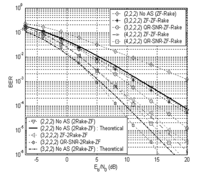
    Fig. 2 shows the BER performance as a function of Eb / N0 in decibels for the SM UWB (3,2,2,2) antenna selection diversity systems with the 2Rake-ZF receiver. The antenna diversity performances of the ZF-Rake receiver with ZF-SNR and QR-SNR-based antenna selection criterion (called ZF-ZF-Rake and QR-SNR-ZF-Rake, respectively) are included for comparison. The transmit antenna selection scheme with one more transmit antenna is shown to significantly improve the performance of the

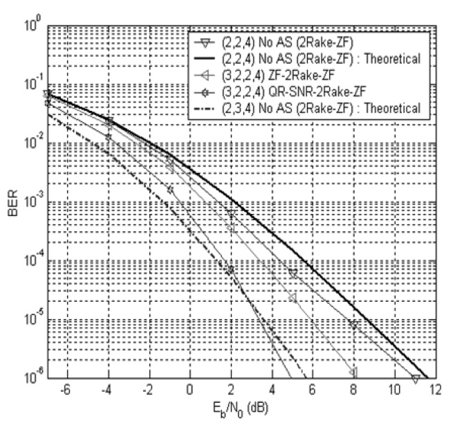
    (2,2,2) 2Rake-ZF receiver with no antenna selection. It is also found that the 2Rake-ZF receiver with antenna selection has much better performance than the ZF-Rake receiver. It is observed that the (3,2,2,2) 2Rake-ZF antenna diversity system outperforms the (4,2,2,2) ZFRake antenna diversity system. It is seen that the QR-SNRSC provides much better performance than the ZF-SC. The BER performance of the (3,2,2,4) 2Rake-ZF system with L = 4 resolvable multipath components versus Eb/N0 in decibels is evaluated in Fig. 3. It is shown that the antenna selection scheme enhances the performance of the 2Rake- ZF receiver even with more resolvable paths, but the degree of performance improvement, which is the performance gap between the antenna selection diversity system and no antenna diversity system, is reduced.

    Using expression (9), theoretical BER results of the 2Rake-ZF systems are also plotted in Figs. 2 and 3. It is shown that the (2,3,2) and (2,3,4) 2Rake-ZF MIMO systems can be regarded as full complexity antenna systems without antenna selection of the (3,2,2,2) and (3,2,2,4) 2Rake-ZF antenna selection systems, respectively. The ZF- 2Rake-ZF has almost the same asymptotic slope as the full system, which means that it can provide the same diversity gain as the full system. Meanwhile, the QR-SNR-2Rake-ZF has a slightly larger slope than the full antenna system, which implies that it offers an additional SNR gain. Thus it is confirmed that the antenna selection achieves the diversity order of the full system.

    V. CONCLUSIONS

    The BER performance of a SM UWB system with transmit antenna selection has been evaluated over indoor log-normal fading channels. The employed receiver consists of maximal ratio combiners and multipath combiners that capture LNR resolvable paths in the space and time domain and then a ZF detector to spatially process the NS parallel transmitted data streams. It has been shown that the transmit antenna selection algorithms based on the largest minimum post-detection SNR significantly boost the BER performance of the 2Rake-ZF receiver when the number of multipath combined in time is relatively small. It has been observed that the 2Rake-ZF scheme outperforms the ZF-Rake even with the transmit antenna selection process. It has also been observed that the QR-based antenna selection criterion offers much better performance than the ZF-based selection one. Furthermore, it has been confirmed that the diversity advantage gained by antenna selection is similar to that of the full complexity antenna system.

참고문헌
  • 1. Kaiser T, Zheng F, Dimitrov E 2009 "An overview of ultra-wideband systems with MIMO," [Proceedings of the IEEE] Vol.97 P.285-312 google
  • 2. Molisch A. F, Win M. Z 2004 "MIMO systems with antenna selection," [IEEE Microwave Magazine] Vol.5 P.46-56 google
  • 3. Mun C 2006 "Transmit-antenna selection for spatial multiplexing with ordered successive interference cancellation," [IEEE Transactions on Communications] Vol.54 P.423-429 google
  • 4. Heath Jr R. W, Sandhu S, Paulraj A 2001 "Antenna selection for spatial multiplexing systems with linear receivers," [IEEE Communications Letters] Vol.5 P.142-144 google
  • 5. Tsai S. H 2011 "Equal gain transmission with antenna selection in MIMO communications," [IEEE Transactions on Wireless Communications] Vol.10 P.1470-1479 google
  • 6. Kim S 2012 "QR decomposition-based antenna selection for spatial multiplexing UWB systems with zero-forcing detectors followed by rake combiners," [IEICE Transactions on Communications] Vol.95B P.337-340 google
  • 7. Liu H, Qiu R. C, Tian Z 2005 "Error performance of pulse-based ultra-wideband MIMO systems over indoor wireless channels," [IEEE Transactions on Wireless Communications] Vol.4 P.2939-2944 google
  • 8. An J, Kim S 2009 "Spatial-temporal combining-based ZF detection in ultra-wideband communications," [IEICE Transactions on Fundamentals of Electronics, Communications and Computer Sciences] Vol.92A P.1727-1730 google
OAK XML 통계
이미지 / 테이블
  • [ Fig. 1. ]  Block diagram of 2Rake-ZF receiver with transmit antenna selection. ZF: zero-forcing, SNR: signal-to-noise ratio.
    Block diagram of 2Rake-ZF receiver with transmit antenna selection. ZF: zero-forcing, SNR: signal-to-noise ratio.
  • [ Fig. 2. ]  Bit error rate (BER) versus Eb /N0 in (3,2,2,2) 2Rake-ZFsystems. ZF: zero-forcing, No AS: no antenna selection, SNR: signal-tonoiseratio.
    Bit error rate (BER) versus Eb /N0 in (3,2,2,2) 2Rake-ZFsystems. ZF: zero-forcing, No AS: no antenna selection, SNR: signal-tonoiseratio.
  • [ Fig. 3. ]  Bit error rate (BER) versus Eb/N0 in (3,2,2,4) 2Rake-ZF systems. ZF: zero-forcing, No AS: no antenna selection.
    Bit error rate (BER) versus Eb/N0 in (3,2,2,4) 2Rake-ZF systems. ZF: zero-forcing, No AS: no antenna selection.
(우)06579 서울시 서초구 반포대로 201(반포동)
Tel. 02-537-6389 | Fax. 02-590-0571 | 문의 : oak2014@korea.kr
Copyright(c) National Library of Korea. All rights reserved.