In this paper, we proposed a novel location estimation algorithm based on the concept of space-time signature matching in a moving target environment. In contrast to previous fingerprint-based approaches that rely on received signal strength (RSS) information only, the proposed algorithm uses angle, delay, and RSS information from the received signal to form a signature, which in turn is utilized for location estimation. We evaluated the performance of the proposed algorithm in terms of the average probability of error and the average error distance as a function of target movement. Simulation results confirmed the effectiveness of the proposed algorithm for location estimation even in moving target environment.
Recent growth of interest in pervasive computing with sensing and location-aware capabilities provides a strong motivation to develop new techniques for accurately estimating the location of devices in wireless sensor networks [1-3]. The Federal Communications Commission (FCC) has amended its rules to permit the use of improved radio frequency identification (RFID) systems to facilitate seaport security efforts [4]. One of the representative standards of these applications is the real-time locating system (RTLS) that is intended to provide an approximate location (within 3 m in a line-of-sight [LOS] environment) with frequent updates [5].
Many wireless location techniques have been investigated and can be divided into two approaches: geometric-based techniques, such as angle of arrival (AOA) [6], time of arrival (TOA) [7], time difference of arrival (TDOA) [8], and location fingerprinting approaches [9,10]. In the case of AOA, TOA, and TDOA, location estimation is based on triangulation techniques that require LOS between the transmitter and the receiver. However, in practical wireless environments, it is difficult to guarantee a LOS path between the transmitter and the receiver. Therefore, the estimation accuracy is considerably reduced in non-line-of-sight (NLOS) environments. On the other hand, location fingerprinting techniques solve the problems related to NLOS and multipath propagation by using a “ radio map” of the received signal strength (RSS) for a target environment. Thus, in this study, we focused on location fingerprinting approaches since they are more suitable for NLOS applications [9,11,12]. Unfortunately, most existing research has only used RSS information. The location is estimated by comparing the current measured data with the “ radio map” of the pre-measured database. However, this has limited value for some applications, such as outdoor scattering environments where radio signal propagation is very complicated because of severe multipath effects.
In this paper, we investigated a location estimation algorithm for RTLS consisting of RFID tags and multiantenna readers and propose a novel location estimation algorithm based on the concept of space-time signature matching in NLOS multipath environments. The proposed algorithm uses angle, delay, and RSS information from the received signal; this is in contrast to previous fingerprintbased approaches [9-12], which rely on RSS information only to form a signature that is in turn utilized for location estimation. In [3], we already proposed a location estimation algorithm based on space-time signature matching in NLOS environments. In this case we assumed there was no target movement, i.e., the target location was fixed. However, in real wireless environments, one cannot expect that a target location is fixed. Hence the target mobility scenario is a practical assumption. Therefore, this paper can be regarded as an extension of the previous study [3] to the more complicated scenario when there is a target random movement. We evaluated the performance of the proposed algorithm in terms of the average probability of error and the average error distance as a function of target movement. The organization of the paper is as follows. Section II provides a description of the system model. Section III describes the proposed location estimation algorithm based on the space-time signature matching technique and presents a detection method. In Section IV, simulation results are presented to verify the effectiveness of the proposed algorithm. Conclusions are given in Section V.
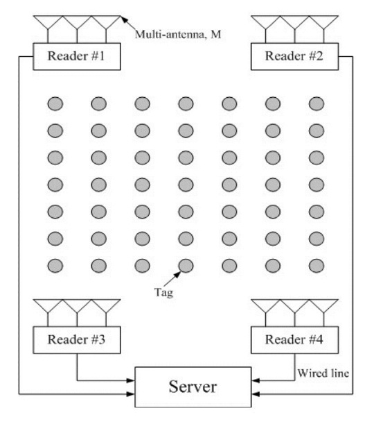
RTLS is an automatic system that continually monitors the locations of objects. The system continually updates the database with current tag locations as frequently as every several seconds or as infrequently as every few hours depending on the mobility of the target tags [13]. The RTLS infrastructure, as shown in Fig. 1, typically consists of RTLS transmitters (radio tags), RTLS receivers (readers), and the RTLS server. RTLS transmitters blink (or transmit) a direct sequence spread spectrum (DSSS) signal, and RTLS readers, whose locations are fixed, receive signals from the tags. The RTLS server aggregates data from the RTLS readers and determines the tag’s current location.
In this paper, we assume that each reader is equipped with an array of
We assume that
III. LOCATION ESTIMATION ALGORITHM
>
A. Space-time Signature Matching
In this paper, we propose a novel method based on spacetime signature matching to accurately estimate the location by utilizing not only the RSS but also the angle and delay information of the received signal.
The proposed space-time signature matching algorithm is carried out in two steps. In the first step, reference signatures are generated for every reference point. A tag at an unknown location can then be estimated by comparing the signature generated from the received signal with the reference signatures. We assume that there are
Step 1: reference signature database generation
Place a transmitter at one of the reference positions and let it transmit a known spread spectrum waveform.
Readers receive the waveform and generate a signature vector of this location. Denoted by Ψi(k), the signature vector of the i -th reference point is measured at the k-th reader.
These signatures Ψi(k), k = 1,2, … . , K along with the corresponding reference coordinates (xi, yi) are saved in the database located in the server.
Move to the next reference point until all reference points, i = 1,2, … . , Nr are visited.
Thus, for Nr reference points, the database consists of NrK signature vectors, Ψi(k), i = 1,2. … , Nr, k = 1,2, … . , K.
Once the reference signatures are obtained, we can locate a tag at an unknown position as follows.
Step 2: location estimation process
A tag at an unknown location transmits a known waveform and the readers compute a signature

, k = 1,2, … . , K based on the received signal.
Compare the currently computed signature with the reference signatures in the database.
Estimate the unknown tag’s location by finding the location in the database whose signatures are closest to the currently obtained signature. All information (i.e., angle, delay, and RSS information at each reader) is used or combined to estimate the tag location.
>
B. Path Partitioning in Angle and Delay
The main concept of our algorithm is that the estimation accuracy can be greatly improved by working with a detailed signature of the scattering environment. The detailed signature consists of the angle, delay, and path gain associated with each scatterer, which provides more information to the estimator than the conventional RSSbased methods. Such information buried in the regular channel vector or matrix clearly shows up in the virtual channel vector.
A key property of the virtual channel representation is that its coefficients represent a resolution for the multipath in angle and delay commensurate with the signal space parameters M and W , respectively [14-16]. The angledelay virtual representation partitions the multipath responses into distinct angle-delay resolution bins.
>
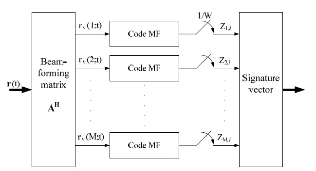
C. Generation of Signature Vector
The signature vector is what we eventually use to estimate the location. It is computed from the received signal at each reader, as illustrated in Fig. 2. A more detailed description of the generation of the signature vector is given in [3].
{
After obtaining signature vectors from all reference points, the readers constantly monitor the field. When a strong signal is detected, each reader forms a signature vector
from the received signal. The maximum likelihood decision for the location is then made. We considered noncoherent detection to be a detection method.
When a tag of unknown location is placed at one of
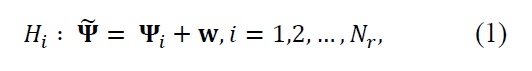
where
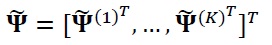
and
Ψ
The probability density function (pdf) of

given
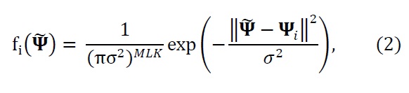
where ll·ll represents the Euclidean norm of a vector. Hence the maximum likelihood estimation of the tag location is made as follows:
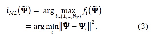
which implies that the maximum likelihood decision is equivalent to simply finding a reference signature that is closest to the observed signature.
The coherent detection method in (3) is optimal only in ideal settings. That is, in order for the method to produce a good estimate of the location, two conditions should be satisfied. First, the transmitter and receiver should be phase-synchronized. A mismatch in the phase of the carrier causes a phase shift in the entries of a signature matrix. The phase shift of entries of
can induce a large error in the Euclidean norm of the difference between the observed and reference signatures in (3). Second, a tag should be placed exactly at one of the reference points. Otherwise, even a short distance may induce a significant phase shift and deteriorate the estimate accuracy. For example, if a tag is placed 10 cm from a reference location, it corresponds to
radians of phase shift when a 2 GHz carrier frequency is used. However, both conditions are difficult to satisfy in practical situations. This motivates the development of a new location estimation method that is resilient both to the carrier phase mismatch and to the location offset.
For the reasons discussed above, we cannot rely on the phase part of the entries of the signature matrices, but should base our decision on their magnitude. Although we discard the phase part, we still can distinguish locations because different locations induce different delays and angles-of-arrival, which appear as nonzero elements at different bins with different strengths in the signature matrices.
In the new method, which we term non-coherent detection, we form a database of variance matrices at reference points instead of that of signature matrices. Variance matrices can be estimated by transmitting a known signal a number of times in the vicinity of each reference point. We estimate the
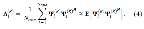
where

is the sum of error-free variance Λi(k) and noise variance σ2I. Using this, we model the distribution of a signature matrix at the
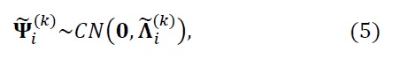
and we assume that the variance matrix is diagonal, which follows from the path partitioning explained in Section III-B. We further assume the mean to be zero because of the randomness of the phase part of a signature matrix. Denoting by
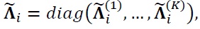
the pdf of a signature matrix when
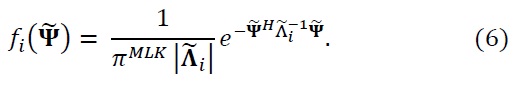
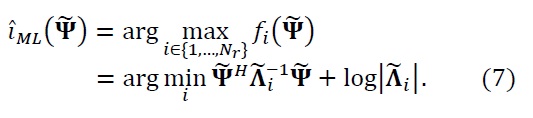
This leads to the maximum likelihood detection of
We can obtain the upper-bound of the error probability for non-coherent detection as
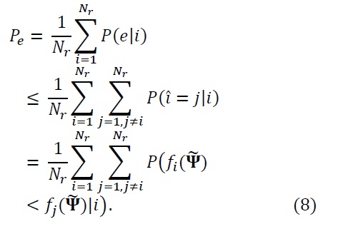
From (5) and (7), one can see that
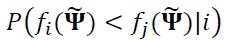
is completely determined by

and

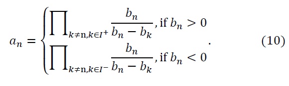
, respectively. This probability has exactly the same formulation as the error probability of a covariance matrix-based binary hypothesis test, and the closed form solution is as follows:
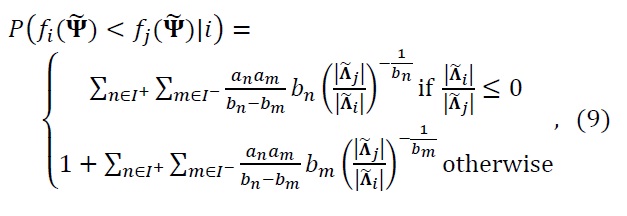
where
IV. SIMULATION AND DISCUSSIONS
>
A. Generation of Multipath Channel
We considered a field of a 300 × 300 m square region. We assumed that reference tags were randomly distributed over the region, and four readers equipped with five antennas each were placed in the corners of the region. Twenty rectangular-shaped scatterers were placed inside the region in a random manner. We measured the signature vectors at the reference tag positions separated by 3 m. In order to generate realistic multipath channel realizations that are suitable for wireless environments, we developed a site-specific channel simulator based on the deterministic 2D ray-tracing technique. A more detailed description of the multipath channel realizations is explained in [3].
The effectiveness of this approach for enhancing the accuracy of location estimation in NLOS environments was validated through computer simulation. In the simulation, 1,135 tags were considered to be reference positions and the transmit signal-to-noise ratio (TXSNR) was used as a SNR criterion. The estimation performance of the proposed algorithms was evaluated in terms of the average probability of error and the average error distance
where (

, respectively, represent the true and estimated coordinate of a tag and
Figs. 3 and 4 compare the estimation performance of coherent detection [3] and non-coherent detection algorithms for different tag mobility scenarios: fixed location and random movement. For the fixed-location scenario, tags of unknown location were placed exactly at one of the reference points and the location was estimated. In the random movement scenario, they were placed on the circle of a certain radius centered at one of reference points, and the estimation was carried out. In real settings, one cannot expect tags attached to containers, for example, to be placed exactly (i.e., within 0.01 m) at the reference points. Hence the random movement scenario is a practical assumption.
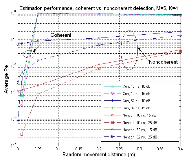
Fig. 3 illustrates the effect of random movement of a tag on the average error probability for M = 5 and K = 4. It can be observed that the estimation performance of coherent detection is superior to that of non-coherent detection if there is no or negligible movement (i.e., 0.01 m). However, the performance of coherent detection drastically degrades with meaningful movement (i.e., 0.05 m or more) regardless of the system bandwidth (i.e., delay resolution) and TXSNR. This is due to the sensitivity of the Euclidean norm on the phase part of a vector. For example, two complex vectors [a1 a2] and [a1
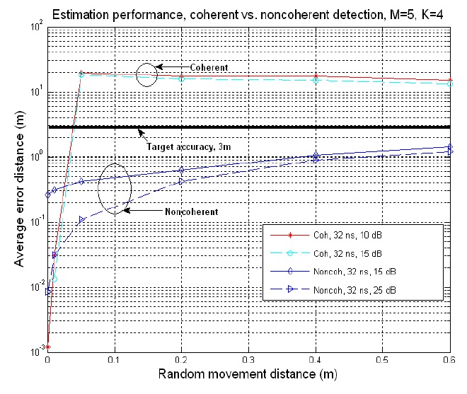
Fig. 4 shows the effect of random movement of a tag on the average error distance for M = 5 and K = 4. We investigate the error distance because it is important whether the erroneous location estimation is the close neighbor of the true location or not. The RTLS specification also describes the requirement in terms of error distance. This figure shows that the average error distance behaves similarly to the average error probability. An interesting observation is that non-coherent detection performs much better than the average error probability graph implies. The error probability was about 10 to 20% with a 32 ns delay resolution and 15 or 25 dB TXSNR at 0.4 m from the reference points. However, the average error distance is only about 1 or 2 m. This implies that the errors mostly occur at the immediate neighbors of the true location.
In this paper, we investigated location estimation algorithms for real-time location systems and proposed a novel location estimation algorithm based on the space-time signature matching in a moving target environment. We derived the upper-bound of the average error probability for non-coherent detection and carried out simulations. A 2D ray tracing technique was used in generating multipath channel realizations. Simulation results show that when tags are placed exactly at the reference points, coherent detection works much better than non-coherent detection. However, when they are placed even a fraction of 0.1 m from the reference points, one should use the non-coherent detection algorithm, which provides an accuracy of less than 2 m with most practical system parameters when reference point spacing is 3 m.