The vast potential applications of wireless sensor networks (WSNs) have attracted extensive research efforts. Conventional networks support mostly point-to-point or point-to-multipoint data forwarding [1].
On the other hand, WSNs are often deployed to sense, process, and disseminate information on targeted physical environments. Furthermore, sensor nodes are deployed in large numbers and high density, thus resulting in a potentially huge amount of sensory data, which is often impractical to transmit to the sink directly, particularly from the perspective of energy conservation. Also, the deployed sensors are capable of communicating with each other across short distances. Therefore, data aggregation is required with cluster formation to effectively gather the data from the widespread sensors, and a hierarchical to curtail the network load and hence reduce energy consumption [2,3].
The traditional topology-based WSN routing protocols are quite susceptible to node mobility mainly due to the predetermination of an end-to-end route before data transmits.
Owing to the frequent and constant changing of the network topology, it is actually difficult to maintain a deterministic route. Therefore, link failure discovery and recovery procedures also consume time and energy.
The most critical requirements of WSNs are achieving the expected throughput as well as covering the entire network efficiently. According to some previous studies on WSNs, it is a challenging job to maintain the mobile sensors in network construction and data forwarding. The flooding/ multicasting technique is an efficient approach to broadcasting the control/data packets in an environment where neither the sensor nodes nor the sink are stationary. However, it poses serious new challenges (i.e., idle-listening in the media access control (MAC) layer and control packet overhead) for WSN applications in which the constituted nodes move around.
For the above reasons, sensor nodes are prone to huge computational costs, which result in frequent death of some deployed nodes. The frequent death of nodes can bring about a link failure and/or partition in the network. In such cases, network reconstruction and maintenance must occur within a short period of time. This tends to bring about high energy consumption, which also degrades the network lifetime. To resolve this well-known problem, the most common approach is to make use of a hierarchical and clustering approach in the network construction and data forwarding.
The scheme presented in this paper differs from the conventional clustering approaches, and is designed to satisfy the requirements of node mobility, as follows.
1) Our scheme constructs the network based on a hierarchical approach (e.g., from source to destination) to distribute the tasks to avoid a huge computational cost to a specific node.
2) The control node election and the data routing both are follow a hierarchical approach that will reduce the control/data packet overhead in the whole network.
3) The periodic change of specially functioning nodes will support overcoming link failure/network partition due to the death of intermediate nodes in communication links.
4) Also, our scheme includes a method for collecting the missing data from a missing node that comes from out of the communication range.
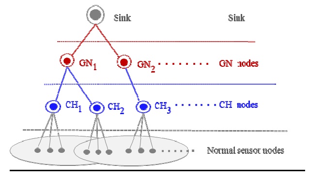
This work presents an energy-efficient cluster formation and maintenance (ECM) scheme for WSNs based on a hierarchical approach. The initial construction of the network will be initiated from the sink by electing gateway nodes (GNs) in the entire network. The elected GNs will participate in cluster head (CH) election to distribute the network area into several logical clusters. The elected CHs among the member sensor nodes will form an individual logical cluster. All these procedures are maintained as a top-down process from the sink to the normal sensor nodes. The normal sensor nodes, which are members of their corresponding CHs, will sense data from their own environment and forward it to the CHs. The CHs take a role of aggregator of the sensed data, and are responsible to forward it to the GNs. Finally, the GNs will transmit it to the sink based on the current location of sink. Therefore, the data forwarding will be maintained in the bottom-up procedure.
The remainder of this paper is organized as follows. We briefly discuss the works related to the routing vs. energy consumption point of view in Section II. In Section III, our proposed scheme is described in detail. Section IV shows the simulation results. Finally, Section V concludes our work.
There are various routing protocols used for WSNs, but they are commonly application-specific [4]. Some of them are proactive and designed for static networks like DSDV [5], some are reactive and designed for mobile networks like DSR [6], and some are hybrid protocols like AODV [7]. Most of them are not suitable to directly apply to WSNs due to the high computational cost. In order to resolve this problem, there are several works based on hierarchy and clusters as follows.
LEACH [8] is a hierarchy and clustering-based protocol for periodic data gathering applications in WSNs. Sensor nodes elect themselves as CHs at any given time with a predefined probability. While these CHs advertise their status, the member nodes determine which cluster they want to join based on strength of each received signal. Nevertheless, the probability that there is only one CH or there is no CH is high when the desired number of CHs is small. Thus, when no CH is elected, all nodes must send data to the base station directly, which is not suited for short distance-capable tiny sensor nodes.
PEGASSIS [9] is a chain-based protocol that allows only one node (the leader) to transmit data to the sink in each round and requires the other nodes to instead transmit only to nearby neighbors. The key idea of this scheme is chaining and fusion. To construct a chain, each node determines its closest neighbor and forms a chain by employing a greedy algorithm. However, this protocol is not preferable for mobile nodes. Moreover, link failure/network partition can occur due to the death of an intermediate node in the chain.
DLER [10] is based on the idea that the sink elects a set of landmarks in the network to route data from the sensing field to the sink. To elect the landmarks, three different transmission ranges are used to broadcast control packets. After completion of the landmarks’ election, the normal sensor nodes forward their sensed data using the greedy forwarding method based on the neighboring landmark information. However, this protocol is based on a static scenario of the constituted nodes, which does not take into consideration the energy level of a node determining whether it is a landmark. The different transmission ranges in each landmark election process dissipate more energy, which may lead to the quick death of those landmarks not long afterward. Moreover, the least number of landmarks near the sink may cause the dropping of the significant number of data packets from distant landmarks.
EER [11] is a hierarchy and clustering-based protocol that can support mobile sensor nodes as well as mobile sinks. To solve the mobility issue of sensor nodes, this protocol makes use of two CH nodes and a GN is required in each cluster, where CHs play the role of an aggregator for data from their sensor nodes and transmit data through the GN. Eventually, the GN will transmit the aggregated data to the sink. However, this protocol violates the conventional definition of a cluster, where one CH should be elected in a cluster. Thus, it is not an efficient approach to elect more than one CH in a cluster, and arbitrate their corresponding roles. This means that it required more control packets, which induces a greater computational cost and consequentially degrades the network lifetime significantly.
The witness of the previous works shows that they emphasized constructing a network based on routing efficiency rather than overall energy dissipation, where the practical WSN application deserves to take on the last sensor node’s functionality during the expected network lifetime.
III. PROPOSED ENERGY EFFICIENT CLUSTER AND MAINTENANCE SCHEME
Our work aims to construct a network from an energyefficient perspective, and to provide data delivery safely from the deployed sensor nodes to the sink. To begin with, it is based on the following assumptions:
1) The ID of a node is unique.
2) Nodes are homogeneous and energy constrained.
3) Nodes are mobile and able to adjust their transmission range.
In addition, we make use of the basic time division multiple access (TDMA) method in the MAC layer of the constituted nodes. After completion of the network construction phase, all the deployed sensors will maintain their allocated TDMA schedule. Data transmission from the normal sensor nodes to the CH, from the CH(s) to GN, and finally from the GN to the sink would be according to their own TDMA schedule.
The proposed scheme consists of three phases. The first phase is the initial network construction phase, where the sink initiates to elect GNs in the network. The elected GNs take charge of electing CHs, where a CH corresponds to each logical sub-region of the network. In addition, the GNs transmit data delivered from their relevant CH(s) to the sink. The CHs will form logical clusters exclusively based on the information from the normal sensor nodes provided by the GNs. Also, the CHs take on the role of the aggregator of the data from their member sensor nodes and transmit the data to the sink through the GNs.
In the second phase, which is the data forwarding phase, the deployed sensors will start to accumulate information from their surrounding environments and transmit the data to the sink using their corresponding intermediate nodes (i.e., CH and GN in sequence). The last phase is called a network maintenance phase. Along with the mobility of the constituted node, the initial network structure will be broken, so network maintenance and reconstruction is required for an individual cluster or the entire network.
>
A. Initial Network Construction Phase
This phase performs the setup of an efficient hierarchical structure of the network. It defines the special purpose nodes, such as the GNs and CHs, and the logical clusters in order to build a network hierarchy. In the election process, the highest energy level and lowest mobility of nodes are preferable. Each step of the initial network construction phase is as follows.
1) Gateway Nodes (GNs)
The sink first initiates the election process by electing a set of GNs from among the normal sensor nodes. The sink broadcasts a
2) Cluster Head (CH) Nodes
The elected GNs participate in processing the CH node election. Each GN broadcasts the
3) Logical Cluster Formation
The entire network would be distributed into logical clusters. The lower level clusters are grouped by normal sensor nodes and a CH node. The upper level clusters are grouped by CH node(s) and a GN, where logical clusters are connected hierarchically for bi-directional communication.
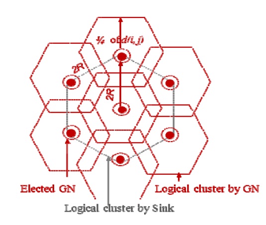
1) Logical cluster formed by the sink: This cluster is initiated by the sink to cover the entire network by elected GNs based on their energy level and low mobility. Fig. 1 shows an example of a well-formed cluster of GNs.
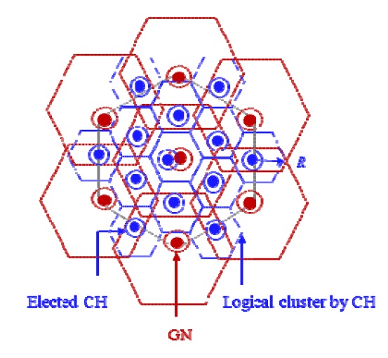
2) Logical cluster formed by the GN: The elected GNs formed the logical clusters by electing CHs in subregions. Fig. 2 shows an example of a well-formed cluster of CHs.
3) Logical cluster formed by CH: The elected CH forms a logical cluster with the normal sensor nodes. Fig. 3 shows an example of a cluster of normal sensor nodes and the overall network hierarchy.
After establishing the network hierarchy, the normal sensor nodes will be initiated to begin sensing data from their surrounding environment and transmitting it to their corresponding CH in the assigned allocated time. The CH will accumulate the data from the different member nodes and transmit the aggregated data through the respective GN in their allocated time. The GN is also an accumulator of data from the member CH(s) and transmits data to the sink directly or in a multi-hop fashion. Thus, the sensed data will be gathering at the sink based on a bottom-up process.
>
C. Network Maintenance Phase
The logical structure of a cluster will be broken with constituted nodes’ movements, when they go out of transmission range and/or node death of intermediate nodes occurs. This mobility feature worsens the efficiency of the proposed scheme. Therefore, two kinds of network maintenance, that is, local maintenance and network reconstruction are required.
1) Local maintenance: The network efficiency in our scheme is significantly degraded due to the mobility of sensors. If a CH node does not receive any data from a member sensor node within the pre-defined time, then the CH will inform the corresponding GN of the fact that the sensor node is missing. Of course, double-checking to verify node death is necessary. The GN node will broadcast a
2) Network reconstruction: This is needed for the network in such situations where the average residual energy of GNs/CHs is below a pre-defined threshold. Network reconstruction is nearly the same as the initial network construction. Basically, the network reconstruction will be maintained hierarchically, where the sink is the initiator to re-elect the GN node for a particular GN cluster or all of the GNs in the network, and each re-elected GN will be an initiator to re-elect CH node(s) within the CH member cluster. Similarly, each re-elected CH forms a cluster with the normal sensor nodes.
We used a network simulator, ns2 [12], which is a discrete event simulator. The primary performance measurement is the increased network lifetime due to energy awareness during network construction and data routing. Moreover, we are interested in how this comparative measure scales with the network size. A WSN may involve thousands of nodes, thus scaling to a large network size is essential for a routing protocol to be applicable to sensor networks.
To represent the sensors’ mobility, we used the random waypoint model, which is similar to CBR [13]. Each mobile node moves at the direction of 0° to 360° to change the current location for a distance
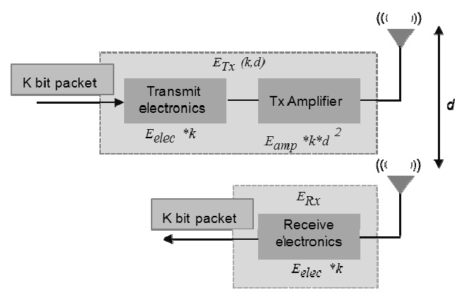
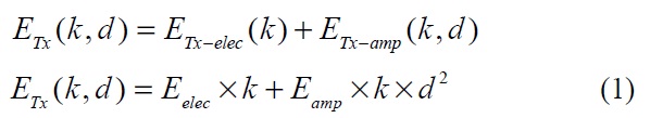
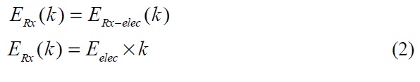
In order to calculate the transmitting and receiving energy, we used the first order radio dissipation model, which is also described in [13] as shown in Fig. 4. In this model, the transmitter and receiver dissipate
The experimental results of ECM are represented in comparison with EER [11] for different criteria. We assumed that the sink is initially located at the center of the designated network field, and moves around with the same pattern and velocity as a sensor node. The sensors are randomly deployed in a (410 × 410) square meter (L × W) area and the transmission range
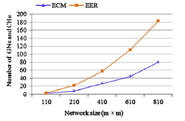
1) Optimized Number of GNs and CHs in Varying Scale Networks
In this simulation, the designated network area is varied from (110 × 110) to (810 × 810), and 6,400 nodes are gradually deployed in the network. The result in Fig. 5 shows that ECM reduces the significant number of GNs (5.19%) and CHs (7.53%), with proper distribution in the entire network. We considered one CH node in a cluster rather than two CH nodes, unlike EER. The greater number of GN and CH nodes in a network consume more energy for broadcasting more control packets. It is also observed that in EER, the 12.72% greater number of nodes leads to quicker death than in ECM.
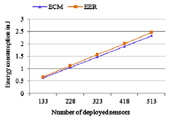
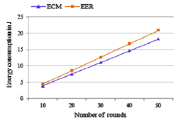
2) Energy Efficiency in Network Construction
In the WSN construction and routing field, energy efficiency is one of the goals for reducing the amount of energy required, and to obtain better services in the network lifetime. From the energy efficiency point of view, the network construction cost is shown in Fig. 6. To evaluate the cost, 133 to 513 nodes are randomly deployed in a (410 × 410) network area in different rounds, as described in Section III. As it is, the energy consumption mainly depends on the number of elected GN and CH nodes. ECM consumes 0.025% less energy in the GN and CH election phase due to the smaller number of elected GN and CH nodes than that of EER.
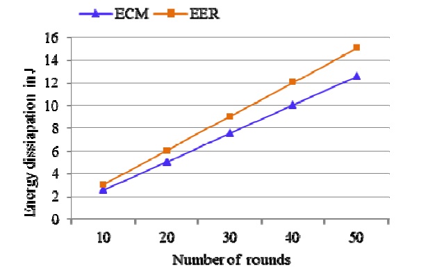
3) Idle-listening Energy Dissipation
Idle-listening is the dominant mode which continuously consumes a sensor’s energy. In most existing protocols, such as IEEE 802.11, a power-saving mode (PSM), attempts to reduce the time spent in idle-listening by sleep scheduling. We applied 2 ms for each time slot in TDMA in its MAC layer and considered 19 frames as a round. It is estimated that, in EER, the normal sensor nodes dissipate 3.62% more energy than that used ECM due to the two consecutive time slots allocated by two CHs for a member sensor node in a cluster. The results are shown in Fig. 7.
4) Routing Efficiency
There are 133 nodes randomly chosen among the deployed sensors to transmit data to the sink in their respective allocated time slots. To calculate the routing cost, we considered 19 clusters (of radius
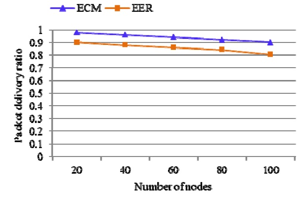
5) Packet Delivery Ratio
The objectives of WSNs are to perform proper actions based on the received information from the deployed sensors in specific sensing environments. Therefore, the packet reception ratio at the sink plays an important role in WSN applications. To analyze the level, we gradually increased the number of sensors deployed to participate in data forwarding. Fig. 9 shows the received packet ratio at the sink of both ECM and EER. Our proposed scheme outperformed than that of EER due to having minimum number of GNs connected with the CHs as intermediate nodes for forwarding data to the sink and adaptively recovering the missing data by GN.
The static and the mobile nodes in a WSN in a large area will provide a communication bridge between the physical world and the tremendously growing information infrastructure. In this paper, we made use of a hierarchical approach from the initial network construction to the data forwarding to reduce the overall cost, especially from the energy consumption point of view. The proposed gateway node concept for a group of clusters is advantageous for observing the mobile sensors and collecting data from missing nodes. With our work, we observed that, distributing tasks into different nodes in a hierarchical fashion can reduce the energy dissipation for some specific nodes, which in turn can reduce the number of node deaths during the network lifetime. Therefore, we conclude that the proposed scheme is able to lengthen the lifetime of the network effectively. In future work we plan to enhance our scheme for the location-free self-organizing routing as well as data recovery methods in WSNs.