Three-dimensional (3D) displays can enable us to see natural scenery as it is. Much research has been carried out concerning 3D displays [1-8]. Among them, stereoscopic displays with special glasses or autostereoscopic multi-view displays with a few viewpoints are the representative 3D display technologies being deployed on a commercial scale. These technologies deliver binocular depth cues such as binocular disparity and convergence. However, they do not provide correct accommodation, thus resulting in visual fatigue due to the accommodation-convergence mismatch.
To get around this problem, the holographic 3D display was proposed. The holographic display provides almost perfect depth information by reconstructing the wavefront of the light field [9]. Therefore, the holographic display is free from the above-mentioned problems of conventional stereoscopic and autostereoscopic displays [10]. In spite of its great potential, the current holographic display has many limitations mainly due to the insufficient resolution of the spatial light modulator (SLM). An SLM can modulate the phase of the beam by controlling transparency. Therefore, an SLM can produce the desired wavefronts that eventually produce the desired shape of the object. In order to reconstruct a more complete wave field, the spatial resolution of the SLM should be increased. However, current device technology cannot realize the ultra high resolution SLM required for the holographic 3D display. Due to the insufficient SLM resolution, studies to realize an electro-holographic display face some difficulties such as the narrow viewing angle and small image size.
Various techniques have been proposed to overcome these problems [11]. One common method is to use a horizontal parallax only (HPO) hologram to relieve the SLM resolution requirement. This approach was developed by S. Benton et al. [12]. Their system improves the horizontal viewing angle up to 24 degrees by using an acousto-optic modulator (AOM) and a horizontal scanner array. Y. Takaki et al. enlarge the horizontal viewing angle to 14.6 degrees by using anamorphic projection and a horizontal scanner [13]. Another idea is to arrange multiple SLMs in an array. C. Slinger et al. configured 4 channel active tiling units, delivering 108 pixels in an active area [14]. B. Lee et al. arranged multiple SLMs in a circular arc, extending the viewing angle to 22 degrees [15]. Although these previous studies provide a wider viewing angle, they usually require multiple SLMs or a high speed scanning mechanism with high bandwidth light modulators, which makes the overall system complicated and expensive.
In this paper, we propose a binocular holographic 3D display system using only one SLM. The proposed system configures two optical paths directed to the observer’s eyes using a beam splitter. Holograms of the left and right eyes are sequentially presented by SLM, while the liquid crystal (LC) shutters located in two optical paths operate in synchronicity to deliver the displayed holographic 3D image to the corresponding eye. Therefore, the proposed system provides binocular 3D images without causing the accommodation-convergence mismatch problem. Note that the proposed method is different from the previous stereoscopic binocular holographic display techniques [16]. While the previous technique presents a different twodimensional (2D) image to each eye such that the observer feels depth from binocular disparity, the proposed method presents a different 3D image to each eye such that each eye of the observer sees a 3D images with correct accommodation. Hence, in the proposed method, not only the binocular disparity but also correct accommodation can be presented to the observer. Also note that the proposed method is distinguished from other holographic techniques in that the holograms are used as an image splitting means in place of the parallax barrier or the lenticular lens in conventional multiview autostereoscopic displays [17-18]. In addition, a technique of enhancing the horizontal viewing angle of the holographic 3D display using only a single SLM has been reported [19]. In this technique, the SLM pixels are spatially reconfigured using specialized optics, sacrificing the vertical bandwidth of the SLM. In contrast, the proposed method uses time multiplexing to present different holographic 3D images to each eye without causing vertical bandwidth reduction. Next, we describe the proposed system and present the experimental results. II.
2.1. Configuration of the Proposed System
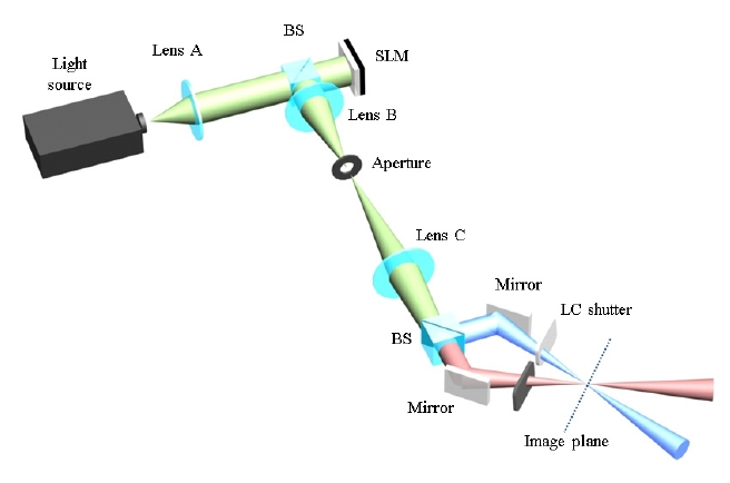
The proposed binocular holographic system is configured as shown in Fig. 1. A light source illuminates the SLM that is sequentially loaded with two holographic patterns of different perspectives of a 3D scene, and the reflected light is decoded by a Fourier transform lens. Next to the SLM, two lenses adjust the scale of magnification of the reconstructed 3D image. The light passing through the lenses is divided into two paths by a beam splitter before reaching the image plane where the final 3D image is located. Each split light is
controlled via a time-multiplexing technique using an LC shutter. Therefore, each reconstructed 3D image containing different perspective is sequentially presented to the corresponding eye.
2.2. Viewing Angle and Image Size of the Reconstructed 3D Image
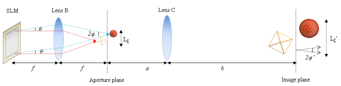
The viewing angle and size of the image reconstructed by the holographic 3D display are fundamentally limited by the number of pixels of the SLM. Figure 2 shows the optical system used in the proposed display configuration. With a pixel pitch
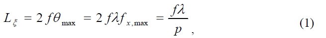
where
where
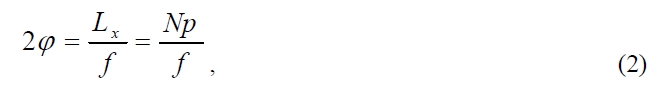
In our configuration, the initial reconstructed image in the aperture plane is magnified by another imaging lens (Lens C
in Fig. 2). The size and viewing angle of the final image located in the image plane are given by
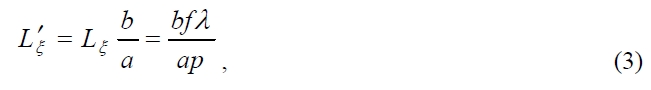
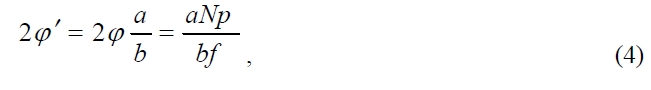
where
2.3. Active LC Shutter Control
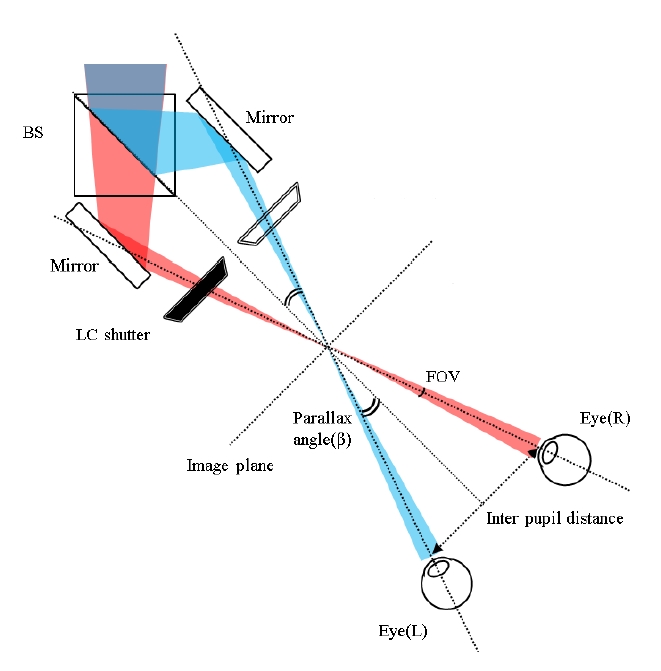
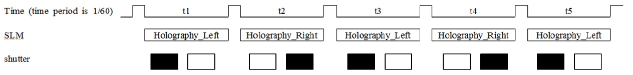
The proposed method uses a binocular holographic system for presenting a left holographic image and a right holographic image. Figure 3 shows configuration of the binocular system setup. An active LC shutter control structure is used to deliver the left and right holographic 3D images to the corresponding eyes of the viewer. Figure 4 shows the synchronized operation of the LC shutters and SLM.
The two active LC shutter lenses can be either transparent or opaque by controlling the electrical voltage. The left and right holographic patterns are alternatively displayed on SLM and are synchronized with the electrical voltage of the LC shutter lenses. When SLM is loaded with the hologram pattern of the left eye, the right lens is controlled to be opaque while the left lens is controlled to be transparent. When SLM displays the right image, the glasses lenses are controlled oppositely. Thus, the observer’s left or right eye only sees a 3D image reconstructed from the hologram pattern of the corresponding eye on SLM. When the left and right 3D images are switched fast enough, the observer will feel natural single 3D image via the after image effect.
2.4. Rotation Geometry for Left and Right Eye Holography
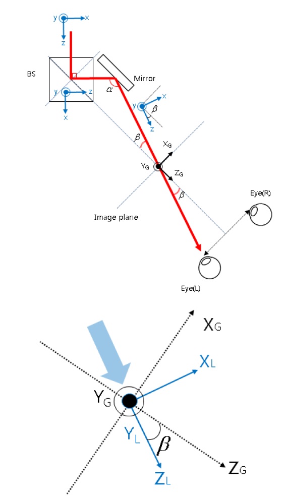
In the proposed system, two light beams containing the reconstructed 3D image are directed in different directions, i.e., left eye direction and right eye direction. Thus, for a given 3D image, holography for each eye should be created considering the beam direction difference, which eventually results in reconstruction of different perspectives of the 3D image.
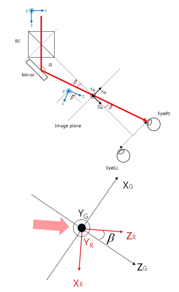
Figures 5 and 6 show the geometry of the beam path for the left and right eyes, respectively. Global coordinates (X
(

Similarly, from the geometry of the right eye beam shown in Fig. 6, the point in the same global coordinates (
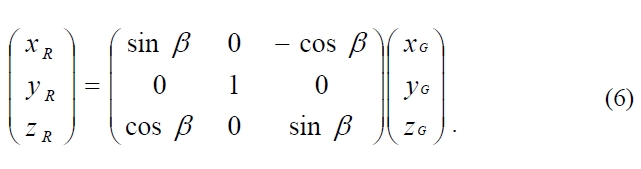
Note that since the coordinates (
In the proposed method, the optical configuration of each of the left and right eye beams is that of the Fourier holography [20-21]. Therefore, for a 3D image U(
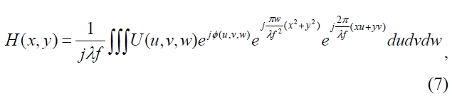
where (
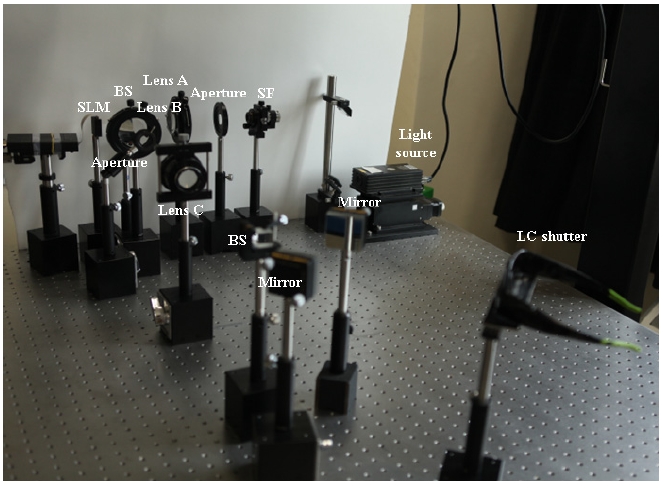
Figure 7 shows the experimental setup. The SLM used in the experiment is a reflective type phase SLM. The resolution of the SLM is 1920×1080 and the maximum refresh rate is 60Hz. SLM was tested using a Michelson interferometric setup under various input-output polarization states, and the optimum condition was obtained before the SLM was used in the experiment. The LC shutter system used in the experiment has a refresh rate of 120 frames per second (120Hz), so that each eye sees 60 frames per second. Note that the proposed method can be implemented using two discrete LC shutters located in the two beam paths and hence there is no need to wear LC shutter glasses to see the 3D images in the proposed method. In the experiment, we used glasses-type LC shutters as a LC shutter system only because they can be easily obtained. Since the SLM is limited to 60 frames per second (60Hz), the final refresh rate of the implemented binocular holographic system is 30Hz.
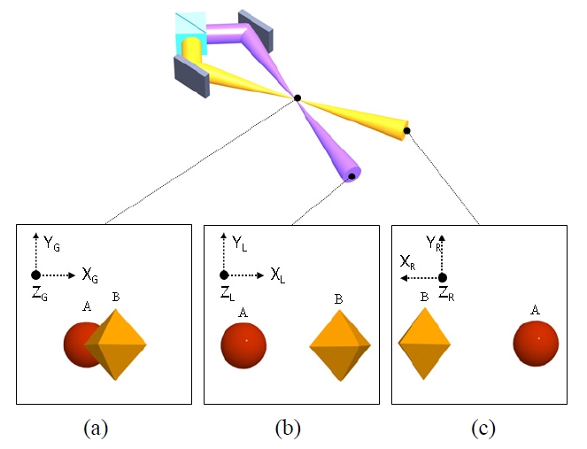
The 3D scene used in the experiment is shown in Fig. 8. Note that two holograms for the 3D scene represented in the global coordinates as shown in Fig. 8(a) are calculated after they are transformed to the left and right beam coordinates as shown in Figs. 8(b) and (c). Hence, each hologram reconstructs the same 3D scene but with different perspectives.
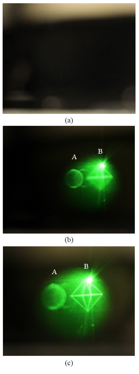
First, we verified the optical operation of the LC shutter. Figures 9(a) and (b) show the pictures taken through an LC shutter that is controlled to close and open, respectively. It can be confirmed that the LC shutter transmits or blocks the view as desired. Figure 9(c) shows the picture taken with a different focal plane of the camera, while the LC shutter is maintained open. By comparing Figs. 9(b) and (c), it can be seen that the different part of the displayed 3D image is focused, which confirms that LC layer of the shutter does not destroy the 3D nature of the displayed image in its transparent state.
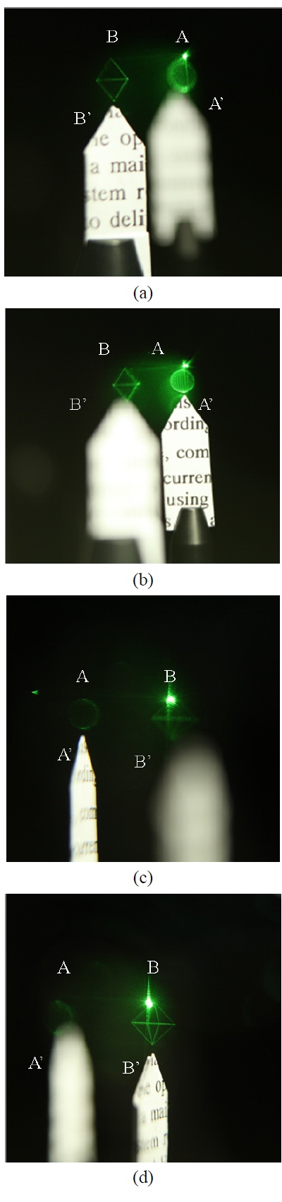
Then, we verified that accommodation and binocular disparity of the 3D image displayed via the proposed method. The 3D
scene shown in Fig. 8 is displayed and two reference objects A' and B' are located where two parts A and B of the 3D scene are displayed. Figures 10(a) and (b) show the pictures taken with different camera focal planes for the right eye view. It can be seen that the 3D images A and B and the reference objects A' and B' are focused at different focal distances as expected. The same result can be observed for the left eye views as well, as shown in Figs. 10(c) and (d). From this observation, it is confirmed that the proposed system can correctly provide the accommodation. Moreover, it can also be observed by comparing Figs. 10(a) and (c) that the displayed 3D images A and B are exactly above the reference objects A' and B', though the viewing direction is altered from right to left view. This means that the location of displayed 3D images in the global coordinates is maintained in the reconstruction of left and right view holograms. Hence,
binocular disparity is also correctly delivered by the proposed method. From the above observations, it can be confirmed that the proposed method can correctly provide both of the accommodation and binocular disparity, eliminating accommodation- convergence mismatch problem of the conventional 3D displays.
In this paper, a novel binocular holographic 3D display
system is proposed. We have combined a time division multi-plexing system using an LC shutter with a holographic 3D display system in order to deliver 3D images to both eyes of the observer. Binocular holographic reconstruction ensures that both of the accommodation and binocular disparity are provided, relieving the accommodation-convergence mismatch problem of the conventional 3D displays. The time multiplexing scheme enables the implementation of the system using only one SLM by eliminating the necessity to enlarge the static viewing angle of the holographic reconstruction.