For the purpose of fabricating off-axis aspheric optics, we propose an 8-axis-polishing machine combined with a testing tower whose height is up to 9 m. The proposed polishing machine was designed and analyzed by using a well-known finite element method. The eight axes of the machine have a synchronized motion generated by a computer, and each axis was calibrated by a heterodyne laser interferometer or an optical encoder. After calibration, the maximum positioning error of the machine was less than 2 ㎛ within a whole 2 m × 2 m area. A typical fabrication result of a Φ1.5 m concave mirror was also described in this manuscript.
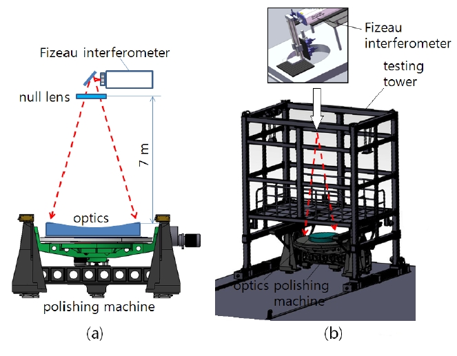
Precision of an optical surface mainly depends on its polishing machine. To accurately fabricate large optics, firstly, the polishing machine must have strict positioning accuracy because the positioning error might be transferred to the final products and has a bad influence on the optical performance of the products. In case of off-axis aspheric optics [1], the positioning error is most important. Secondly, the polishing machine should be combined with an appropri-ate measuring system to fabricate high precision optics. To address these requirements, we propose an 8-axis-polishing machine combined with a testing tower that can measure a wave-front [2-4] of the optics with a Fizeau type dynamic interferometer [5-7] and a null lens [1, 4] as shown in Fig. 1 (noncontact mode). In order to precisely measure the wavefront and/or the surface figure of large aspheric mirrors, environmental factors such as air flow, vibration, and thermal change of the atmosphere, should be considered [8]. Fortunately the dynamic interferometer is able to measure the wavefront with one shot, drastically reducing these environmental effects.
The proposed polishing machine was designed and analyzed by using a well-known finite element method to reinforce the stiffness and the thermal stability of the machine. The eight axes of the machine have a synchronized motion
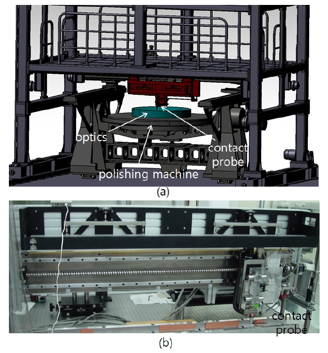
generated by a computer. The maximum capability of the proposed polishing machine is up to 2 m in diameter, and the maximum radius of curvature of the product (optics) is slightly over 7 m. A contact mode measuring by using a probe is also available in the proposed machine as illustrated in Fig. 2. The repeatability of the contact probe (contact mode) and the dynamic interferometer (noncontact mode) were measured as 1 ㎛ and 5 nm, respectively. Figure 3
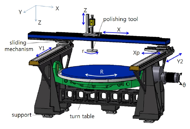
shows the axes of the proposed polishing machine. In this figure, five axes (X, Y1, Y2, Z and Xp) were calibrated by using a heterodyne laser interferometer. Three remaining axes (r, R and θ) were calibrated by an optical encoder [9]. The details are described in the Section II. In Section III, we show some optics fabrication results from using the proposed polishing machine.
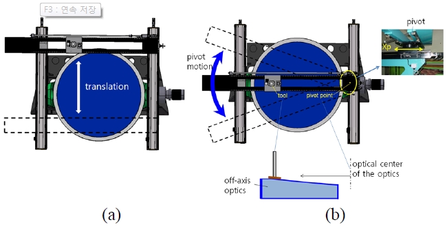
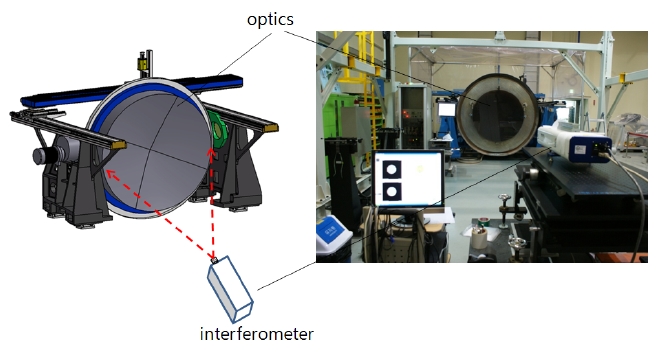
A general polishing tool basically requires a 4-axis-move-ment: a basic 3 translation (X-, Y-, and Z-direction) and a tool rotation (r-direction). In our case, two modes are available. For the first mode, the Y1 and the Y2 motors illustrated in Fig. 3 are synchronized by a controller and make a unified Y translation as shown in Fig. 4 (a). The second pivot mode is generated by the Xp-axis and the sliding mechanism as shown in Fig. 4 (b). Xp-axis is also illustrated in Fig. 3. This figure shows how the pivot mode helps fabricate the off-axis optics. When the pivot point is exactly consistent with the optical center of the optics, the fabrication will be easy. The R- and θ-axes were also inserted in the proposed polishing machine. The product rotates along the R-axis on the turn table, and as shown in Fig. 5, the turn table rotates along the θ-axis to measure the gravity effect of the product according to the posture. Because the gravity effect is one of the serious factors in large optics, it should
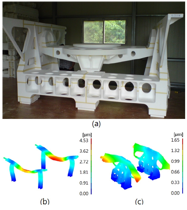
be tested in both zenith- and horizontal-direction during the polishing process. And furthermore, we can measure a product at any θ position between 0° and 90°. To isolate vibration, four supporting mechanisms working as a viscous damper with 14.3 kN ? s/m damping constant were adopted in the proposed polishing machine. To check the structural characteristics, a finite elements analysis program NX I-DEAS[10] was used. The 530,951 solid elements were introduced to take into account the deformation due to gravity. Figure 6 (a) shows the one-bodied-mainframe of the polishing machine. A comparison result between a commonly used frame and our one-bodied-mainframe is displayed in Fig. 6
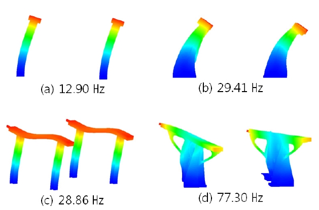
(b) and (c). We were able to drastically reduce the gravity effect (maximum deformation due to gravity) from 45.3 ㎛ to 16.6 ㎛ . A modal analysis results are shown in Fig. 7. The first natural frequency appeared at 29.41 Hz from roll motion of the Y-axis (Fig. 7 (b)). The second one is at 77.30 Hz, which is a mixed shapes from the Y-axis’ yaw and the X-axis’ roll motion as shown in Fig. 7 (d). Note that the vibration performance is certainly improved by adopting our new mainframe.
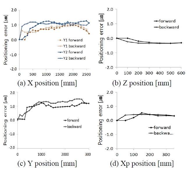
The accuracies of five translation axes (X, Y1, Y2, Z and Xp) were measured by a commercial heterodyne laser interferometer whose resolution is about 0.3 nm after the
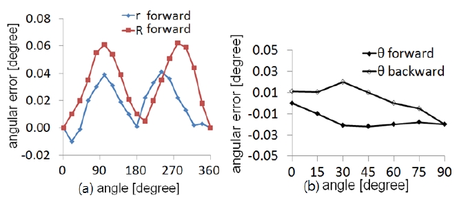
refractive index compensation. The room temperature changed within 22±0.5℃ during the measurement. After calibration, the maximum positioning error of the X-axis (3 m stroke) was 1.77 ㎛ as shown in Fig. 8 (a). Much the same, we obtained a 1.3 ㎛ maximum positioning error for the Y1 (2.5 m stroke), 1.1 ㎛ for the Y2 (2.5 m stroke), 0.84 ㎛ for the Z (0.5 m stroke), and 0.43 ㎛ for the Xp (0.3 m stroke). Three rotation axes (r, R and θ ) were also measured by a commercial optical encoder. Measured results are shown in Fig. 9. These r- and R-directional angular errors are negligible because small amounts of errors are eliminated by over-lapped polishing.
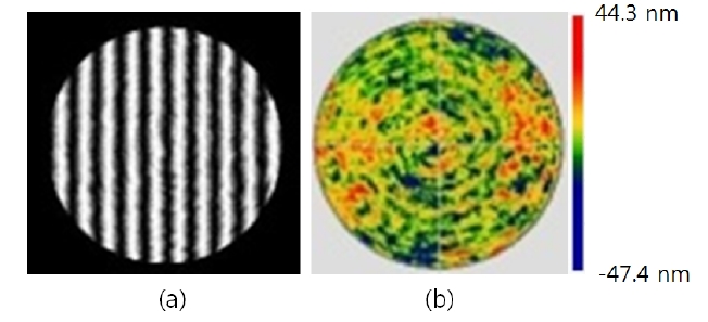
By using the proposed polishing machine, we fabricated a reference concave mirror whose diameter is 1.5 m as shown in Fig. 5. A pitch tool [11] on the flexible layer was selected as a polishing tool to achieve a high quality surface roughness. During the polishing work, the Fizeau type dynamic inter-ferometer (noncontact mode) and the probe (contact mode) were used to monitor the surface change of the mirror. The environmental effects including air flow, and temper-ature change were mostly removed by adopting the dynamic interferometer. Moreover, the common path configuration of the interferometer enables the vibration common to both reference and measurement wavefronts, whereby the inter-ference fringe between them looks static. The final figure error of the mirror was 91.7 nm in PV (Peak-to-Valley) value, and 8.86 nm in
To fabricate a large off-axis aspheric optics, we have developed an 8-axis-polishing machine combined with a testing tower that can measure a product by a contact (point probing) and a noncontact (Fizeau type dynamic interferometer) instrument. The accuracies of the contact and the noncontact mode were less than 1 ㎛ and 5 nm, respectively. During design, several possible machine structures were considered and a suitable layout was selected. The gravity effect and the natural frequency were also observed. The maximum capability of the polishing machine is up to 2 m in diameter,and the maximum radius of curvature of the product is slightly over 7 m. Each axis of the polishing machine was calibrated by a heterodyne laser interferometer and an optical encoder. After calibration, the maximum positioning error was less than 2 ㎛ within a whole 2 m × 2 m area. A Φ 1.5 m concave mirror was succesfully fabricated by using the proposed polishing machine.