검색 전체 메뉴
PDF
맨 위로
OA 학술지
Beam Splitting by the Use of Waveguide Airy Beams
  • 비영리 CC BY-NC
  • 비영리 CC BY-NC
ABSTRACT

Here we report Airy beams coupled with waveguide modes. These waveguide Airy (WAiry) beams propagate through layered planar structures inheriting the characteristics of waveguide modes as well as those of Airy beams, such as diffraction-free and accelerating features. In particular, we focus on the WAiry beams associated with backward waveguide modes, showing that the backward feature can alter the trajectories of the WAiry beams significantly. Based on this, we propose a new scheme of waveguide-type polarization/power beam splitters.


KEYWORD
Airy beam , Waveguides , Metamaterials
  • I. INTRODUCTION

    Airy beams, optical versions of the original Airy wavepackets in the context of quantum mechanics [1], are one of several non-diffracting beam solutions whose intensity profiles remain invariant as they propagate through an optical medium. Compared with other types of diffraction-free solutions such as Bessel [2] and Mathieu [3] beams, Airy beams have several unique properties: they are the only non-diffracting solution in the most simple (1+ 1)D configuration and are accelerated during the propagation [4,5]. This acceleration or, to put it more correctly, self-bending is a phenomenal one caused by initial field configurations lacking spatial symmetry. Not only the diffraction-free but also the self-bending features have their origin in the multiple interference between various field components comprising the Airy beam, which maintains its profile during propagation, only changing the peak positions. These attractive characteristics have already been exploited in various applications such as optical trapping/particle manipulation [6,7], plasma waveguiding [8], implementation of Airy plasmons [9], optical bullets [10], dual Airy beams [11], slow non-dispersing wavepackets [12], and the generation of Bessel-like beams [13].

    In this paper, we propose waveguide Airy (WAiry) beams: Airy beams propagating through inhomogeneous media with the help of waveguide modes. They not only retain the diffraction-free and self-bending properties of the Airy beam but also inherit the unique features of the waveguide mode such as polarization dependency and slow-light characteristics. Here, we will focus on the WAiry beam associated with the so-called backward waveguide mode [14] and show that the backward feature can alter the trajectories of the WAiry beams significantly, which makes them applicable to the implementation of polarization or power beam splitters.

    II. WAVEGUIDE AIRY BEAMS

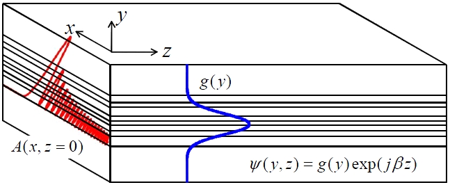
    Let us consider a layered or stacked planar waveguide shown in Fig. 1. We have

    image

    where φ denotes either Ex (TE-polarized case) or Hx (TM case) field. k0 is 2π /λ where λ is the wavelength of light

    in vacuum, ε and μ are the relative permittivity and permeability of the material. We can easily show that

    image

    where ψ (y, z) and g(y) denote a waveguide mode and its transverse profile, respectively, satisfies Eq. (1). A(x, z) is the conventional (1 1)D Airy beam profile given by

    image

    where x0 is an arbitrary scaling factor and α = α ' jα " , α' and α " being related to the initial field profile

    image

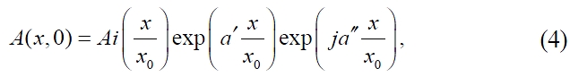
    where we can find that α' is the exponential apodization parameter for the finite energy carried by the beam and α" is the phase modulation factor along the scaled transverse direction [15].

    The above results imply that an Airy beam can propagate in any layered planar waveguides by forming a hybrid beam with waveguide modes. These Airy-like diffraction-free beams, hereafter called waveguide Airy beams or WAiry beams, inherit the characteristics of both the waveguide mode and the Airy beam. We note that WAiry beams are non-diffracting along all spatial directions: diffraction along the y direction is prohibited by the waveguide structure. Along the two other directions diffraction is prevented by the Airy beam profile.

    III. BACKWARD MODE AND THE SPLITTING OF WAIRY BEAMS

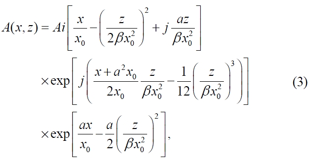
    The trajectory of the WAiry beam can be derived by setting the real argument of the Airy function in Eq. (3) to be zero:
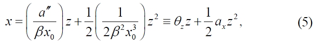
    image

    where αx denotes the acceleration along the transverse (+x) direction and θz is the initial launch angle [see Fig. 2(a)]. As was clearly discussed in [15], Eq. (5) is equivalent to that describing the constant acceleration motion of particles. When we consider a WAiry beam associated with the backward waveguide mode (in the sense that the overall power flow direction is opposite to that of the phase velocity [14]), β becomes negative for forward power coupling. This negative β flips the initial launch angle θ z with respect to z since it retains the sign of β . This flipping, although the acceleration direction does not change at all, enables us to separate WAiry beams associated with forward and backward modes.

    We would like to propose two such cases in which the relevant two modes are forward and backward ones. In all cases, slab waveguides composed of ε -negative (with ε E < 0 and μ E > 0) and μ-negative (with ε M > 0 and μ M <0) metamaterials are adopted. For the first case ε -negative and μ-negative metamaterials are dual singly negative ones (i.e., ε E / μ E =ε M / μM) As was shown in [16], TE and TM modes in slab waveguides made of dual singly negative metamaterials are degenerate, i.e., |βTE|= |βTM|, but one of them is a backward mode, resulting in βTE = -βTM. Therefore, when the polarization state of light changes, the forward waveguide mode also changes into a backward mode (or vice versa). This implies that the WAiry beams associated with TE and TM waveguide modes can be separated due to the difference in their initial launch angles. Figure 2 shows the splitting of TE and TM WAiry beams in slab waveguides made of dual singly negative metamaterials. We assumed εE = -1, μE = 1, εM = 2, μM = -2, a = 0.05 2j, and x0 =1.5λ, and a μ -negative / ε -negative / μ-negative slab structure was considered. The results were obtained using a commercial software (COMSOL) based on the finite element method with the effective index method to reduce the 3D structure into a 2D one. Most optical power flows through the core layer made of an ε -negative medium. The time-averaged Poynting vector <S>, which is inversely proportional to μE and ε E for TE- and TM-polarized light, respectively, becomes forward (TE: β // <S> ) or backward (TM: β // -<S>), depending on the polarization state of light. Therefore, we have θz(TE) >0 and θz(TM)<0, resulting in the separation of TE and TM WAiry beams (i.e., polarization beam splitting).

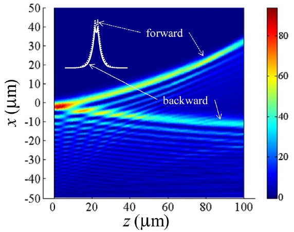
    For the second case the waveguide supports dual modes. Dual modes have the same parity and the same number of zero-crossings, but their directions of overall power flow

    are opposite to each other [14], meaning that dual modes include forward and backward modes. Therefore, the corresponding WAiry beam associated with each of them can also be separated. This characteristic, i.e., power beam splitting, is shown in Fig. 3 where we assumed TM-polarized light waves incident to a μ -negative/ε-negative/μ -negative slab with ε E = -2, μE = 3.5, ε M = 3, and μM = -1. The fact that dual modes have the same parity as well as the same number of zero-crossings, as can be found in the mode profiles shown in the inset of Fig. 3, entails that the coupling efficiencies to two respective WAiry beams associated with dual modes can be made nearly the same, which is very advantageous in the actual implementation of power beam splitters.

    IV. CONCLUSION

    We proposed WAiry beams: Airy-like beams associated with waveguide modes and propagating through planar waveguides. They not only retain the non-diffracting and accelerating properties of the Airy beam but also inherit the unique features of the waveguide mode such as backward powerflow characteristics. We showed that this additional feature of the backward power flow can be utilized to develop a new kind of polarization/power beam splitter.

참고문헌
  • 1. Berry M. V., Balazs N. L. (1979) “Nonspreading wave packets” [Am. J. Phys.] Vol.47 P.264-267 google cross ref
  • 2. Durnin J., Miceli Jr. J. J., Eberly J. H. (1987) “Diffraction-free beams” [Phys. Rev. Lett.] Vol.58 P.1499-1501 google cross ref
  • 3. Gutierrez-Vega J. C., Iturbe-Castillo M. D., Chavez- erda S. (2000) “Alternative formulation for invariant optical fields: Mathieu beams” [Opt. Lett.] Vol.25 P.1493-1495 google cross ref
  • 4. Siviloglou G. A., Broky J., Dogariu A., Christodoulides D. N. (2007) “Observation of accelerating Airy beams” [Phys. Rev. Lett.] Vol.99 P.213901 google cross ref
  • 5. Siviloglou G. A., Christodoulides D. N. (2007) “Accelerating finite energy Airy beams” [Opt. Lett.] Vol.32 P.979-981 google cross ref
  • 6. Baumgartl J., Mazilu M., Dholakia K. (2008) “Optically mediated particle clearing using Airy wavepackets” [Nat. Photon.] Vol.2 P.675-678 google cross ref
  • 7. Cheng H., Zang W., Zhou W., Tian J. (2010) “Analysis of optical trapping and propulsion of Rayleigh particles using Airy beam” [Opt. Express] Vol.18 P.20384-20394 google cross ref
  • 8. Polynkin P., Koleskik M., Moloney J. V., Siviloglou G. A., Christodoulides D. N. (2009) “Curved plasma channel generation using ultraintense Airy beams” [Science] Vol.324 P.229-232 google cross ref
  • 9. Salandrino A., Christodoulides D. N. (2010) “Airy plasmon: a nondiffracting surface wave” [Opt. Lett.] Vol.35 P.2082-2084 google cross ref
  • 10. Chong A., Renninger W. H., Christodoulides D. N., Wise F. W. (2010) “Airy-Bessel wave packets as versatile linear light bullets” [Nat. Photon.] Vol.4 P.103-106 google cross ref
  • 11. Hwang C.-Y., Choi D., Kim K.-Y., Lee B. (2010) “Dual Airy beam” [Opt. Express] Vol.18 P.23504-23516 google cross ref
  • 12. Kim K.-Y., Hwang C.-Y., Lee B. (2011) “Slow non-dispersing wavepackets” [Opt. Express] Vol.19 P.2286-2293 google cross ref
  • 13. Hwang C.-Y., Kim K.-Y., Lee B. (2011) “Bessel-like beam generation by superposing multiple Airy beams” [Opt. Express] Vol.19 P.7356-7364 google cross ref
  • 14. Kim K.-Y., Lee I.-M., Lee B. (2009) “Grating-induced dual mode couplings in the negative-index slab waveguide” [IEEE Photon. Technol. Lett.] Vol.21 P.1502-1504 google cross ref
  • 15. Siviloglou G. A., Broky J., Dogariu A., Christodoulides D. N. (2008) “Ballistic dynamics of Airy beams” [Opt. Lett.] Vol.33 P.207-209 google cross ref
  • 16. Kim K.-Y., Lee I.-M., Lee B. (2009) “Guiding modes of a slab waveguide composed of impedance-matched single negative materials” [IEEE Photon. Technol. Lett.] Vol.21 P.736-738 google cross ref
이미지 / 테이블
  • [ FIG. 1. ]  Geometry of the layered planar structure. ψ (y, z) andg(y) denote a waveguide mode and its profile along thetransverse (y) direction, respectively. A(x, z) describes theconventional (1 1)D Airy beam profile.
    Geometry of the layered planar structure. ψ
 (y, z) andg(y) denote a waveguide mode and its profile along thetransverse (y) direction, respectively. A(x, z) describes theconventional (1  1)D Airy beam profile.
  • [ FIG. 2. ]  (a) Polarization-dependent trajectories of WAiry beams. (b), (c) Power flows (<S> ) through TE and TM WAiry beams, calculated numerically using a commercial software (COMSOL) based on the finite element method. We assumed the operation wavelength (λ) of 1550 nm and a μ-negative/ ε-negative/μ-negative slab waveguide with the core thickness of 300 nm. εE = -1, μE = 1, εM = 2, μM = -2, α= 0.05 2j, and x0 =1.5λwere used. β and <S>denote the propagation wavevector and the time-averaged Poynting vector, respectively.
    (a) Polarization-dependent trajectories of WAiry beams. (b), (c) Power flows (<S>
 ) through TE and TM WAiry beams, calculated numerically using a commercial software (COMSOL) based on the finite element method. We assumed the operation wavelength (λ) of 1550 nm and a μ-negative/ ε-negative/μ-negative slab waveguide with the core thickness of 300 nm. εE = -1, μE = 1, εM = 2, μM = -2, α= 0.05   2j, and x0 =1.5λwere used. β and <S>denote the propagation wavevector and the time-averaged Poynting vector, respectively.
  • [ FIG. 3. ]  Power beam splitting of TM WAiry beams associated with backward and forward dual modes. We also assumed the operation wavelength of 1550 nm and a μ-negative / ε-negative/μ-negative slab waveguide with the core thickness of 89.5 nm. εE = -2, μE = 3.5, εM = 3, μM = -1, α= 0.03 2j, and x0 =1.5λwere used. Inset: actual profiles of dual modes.
    Power beam splitting of TM WAiry beams associated with backward and forward dual modes. We also assumed the operation wavelength of 1550 nm and a μ-negative / ε-negative/μ-negative slab waveguide with the core thickness of 89.5 nm. εE = -2, μE = 3.5, εM = 3, μM = -1, α= 0.03   2j, and x0 =1.5λwere used. Inset: actual profiles of dual modes.