A surface-normal input/output volume holographic grating coupler (VHGC) operating at 1550nm wavelength region by using a 10㎛-thick DuPont photopolymer film is designed and fabricated. The angular and wavelength responses of the input/output VHGC are investigated in order to validate applicability of this device in integrated optics and optical communications. The effect of incident-beam position on the output reflectance to determine optimum condition for input coupling is also presented. The fabricated input/output VHGC exhibited an angular selectivity of ~0.027°, a wavelength selectivity of ~0.8 nm, and an output peak reflectance of 34.13%.
Photopolymer-based input/output volume holographic grating couplers (VHGCs) are attractive elements for coupling lights into and out from waveguides in the field of integrated optics and optical communication applications. Unlike other types of devices used as couplers for optical waveguides-i.e. prism couplers, reflective couplers, and surface-relief grating couplers-, VHGC provides relatively higher coupling efficiency and preferential-order coupling characteristics, and can be fabricated through a dry process at low cost. Because of these advantageous features adaptable to diverse appli-cations of VHGCs, many researchers have proposed various numerical approaches to formulate their characteristics [1-4]. Recently, we have proposed and theoretically investigated an input/output coupler system using volume holographic gratings to achieve high-efficiency coupling with respect to the Bragg-angle mismatch and the index modulation at 1550nm wavelength [5]. The outstanding angular and wavelength selectivity of common reflection-type volume holographic gratings that result from the Bragg effect are expected to make possible a sharp angular and wave-length selective coupling in a VHGC,. This is an advantageous characteristic applicable to wavelength division multiplexing (WDM) systems. The wavelength response of an output VHGC with respect to the index modulation, the waveguide index, and grating thickness, have been analyzed by Villalaz et al. for coarse wavelength division multiplexing (CWDM) system applications [6]. However, there has been a limited experimental demonstration and an analysis to investigate the angular and wavelength responses for the structure of both input and output grating couplers embedded in the waveguide film, this type of coupler may be called an input/output VHGC [7-9].
In this paper, we present the experimental and theoretical study on the angular and spectral responses of the surface-normal input/output VHGC operating at 1550 nm wavelength region. The input/output VHGC is implemented by using a 10㎛-thick DuPont photopolymer HRF600×123-10, which is a high performance holographic film used for transmission and reflection gratings.
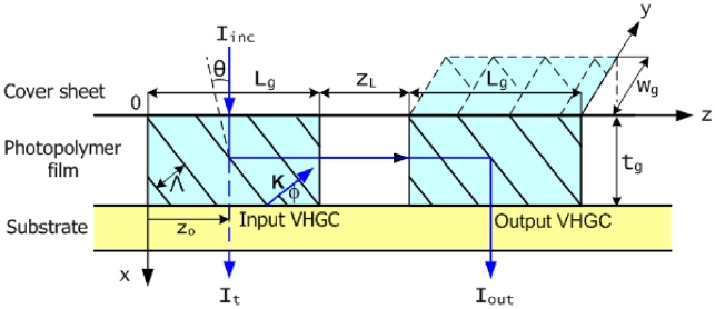
The basic configuration of the input/output VHGC for a surface-normal input-output coupling is shown in Fig. 1. The input/output VHGC consists of a photopolymer waveguide
film, a glass substrate, and a cover sheet. Two VHGCs with gratings of the same length Lg and thickness tg are embedded in the photopolymer film wherein, two couplers are separated by a waveguide of length zL. The photopolymer film acts as both the grating medium and the waveguide layer. In this paper, the two couplers are of identical volume phase gratings with Φ=45° slanted angle, so the grating vector K of the two VHGCs have the same magnitude of |K|=2π/Λ(Λ is the grating period.). A surface-normal-incident input beam is 90° diffracted into the plane of the waveguide by an input VHGC and is guided toward the output VHGC through the waveguide. The guided beam is then 90° diffracted by an output VHGC, therefore the output beam is shifted laterally with respect to the input beam.
To meet the Bragg condition, the grating period Λ must satisfy [10]

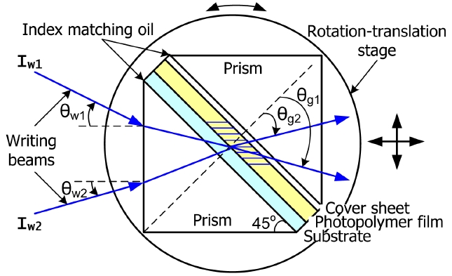
where λr is the wavelength of the incident beam in free-space, ngr is the average refractive index of the grating, Φ is the slant angle of the grating, and θ is the incidence angle of the input beam in the photopolymer. With para-meters ngr=1.49, Φ=45°, and θ=0°, we have a grating period Λ=~0.7355㎛ at 1550nm readout wavelength. In order to fabricate couplers with a 45° slanted volume phase grating into the photopolymer film, the interferometric recording configuration including a prism-pair shown in Fig. 2 is applied. The HRF600×123-10 photopolymer with tg=10㎛ is laminated onto a fused-silica glass substrate with a dimensions of 85mm×25mm×1.5mm after one of the Mylar cover sheets is removed. The dimensions of a fused-silica prism were of 60mm×60mm×25mm, and the prisms were antireflection coated to reduce reflections. The prism system is placed on a motorized rotation stage, and the rotation stage is mounted on the 2-axis translation stages to position accurately the recording beams inside the photo-polymer film. From the geometry of the prism and Snell’s
law, the recording angles at the air-prism interface can be written as


where npw and ngw are the refractive indices of a fused-silica 45°-45°-90° prism and a photopolymer film at recording wavelength λw respectively,
With parameters λw=532nm, Φs=45°, δv=3%, and Λs=0.7355㎛, the resulting recording angles in air of Eq. (2) are calculated to be θw1=26.805° and θw2=16.999° respectively. To attain a high contrast ratio of the recording interference pattern through the compensation of the incident powers for the different recording angles, the intensity of the two recording beams are adjusted to be Iw1=0.15mW/cm2 and Iw2=0.081mW/cm2 respectively. Two gratings with same grating periods are written by the use of translation stages, as illustrated in Fig. 2, to set the separation distance between the gratings. After one grating is recorded, the rotation stage with the prism system is then shifted by a translation stages, and the second exposure is made with a same recording angle to form a grating with a same period. The dimensions and the separation length of the fabricated input/output VHGC are ~8.6mm(=Lg)×7mm(=wg) and 4mm(=ZL)respectively.
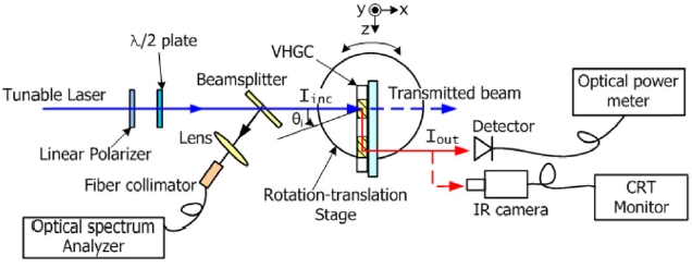
After exposure to the two recording beams, the gratings are fixed by UV light. The fixed sample is then mounted onto a rotation-translation stage in order to test the angular and spectral responses of a fabricated VHGC sample as shown in Fig. 3. A tunable laser which has a center wavelength of 1550nm with a ±30 nm tunable wavelength range is used. The dimensions of the incident laser beam at the surface of the sample were approximately 2 mm(z)×5 mm(y). The polarization of the incident laser beam is controlled by a λ/2 plate and a linear polarizer. Since the VHGC is polarization-sensitive device [12] with strong coupling efficiency for TE polarized light but very weak efficiency for TM polarized light, the TE polarized incident beam was adopted for the experiment. In Fig. 3, the angular tuning is accomplished by rotating the VHGC sample about the y-axis perpendicular to the plane of incidence. In this procedure, angular tuning at a given wavelength leads to a wave-vector mismatch among the grating and the incident and diffracted beams inside the sample, and results in mismatches of a specific waveguide mode. The adjusting procedure for an optimized coupling starts with the first step for tuning a tunable laser to the peak reflectance wavelength for the nearly normal incident input beam. The incident angle is then varied to the coupling angle having a peak reflectance, and then the wave-length is fine-tuned again and the incident angle is fine-tuned around the obtained central values from the first step.
Figure 4 shows the angular response of the normalized reflected intensity for a fixed coupling wavelength of 1547.4nm.The TE polarized input beam was positioned at approximately zo=5mm on the surface of the sample as shown in Fig. 1. We define the output reflectance of the sample as R=(Iout/Iinc)×100% in Fig. 3. Where the incident intensity of the input beam Iinc defines the intensity of the beam transmitted through the film region without the grating at input coupling angle considering the Fresnel and absorption losses, and Iout is the intensity of the deflected output beam from the output coupler.
As seen in Fig. 4, approximately six main TE-modes are excited in the sample, and the shifts in the angular position of the mode curves due to the modal interference are observed. For the fundamental TEo mode, the measured input coupling angle and output reflectance were θc=0.013° and R=6.83%. The higher modes occurs at θc=0.266°, 0.533°, 0.739°, 0.826°, 1.226°, and the corresponding R at these coupling angles were 19.44%, 17.89%, 11.12%, 6.61%, 6.46%, respectively. The angular selectivity of TE1 mode was ~0.033°, which is measured at the half width at first zero (FWFZ) level of the mode curve. Because the VHGC characteristic properties are dominated by the Bragg effect, the angular selectivity inside the φ=π/4 slanted volume grating at the FWFZ level can be described theoretically with the Kogelnik formula as δθFWFZ?λcsinθc/ngrtgcos2θc, where λc is the Bragg phase-matched coupling wavelength of the grating, and θc is the coupling angle inside the grating [10]. Using the measured values in Fig. 4 with θc=0.266° and λr=1547.4nm, we obtain an angular selectivity of δθFWFZ=~0.027° for a grating with tg=10㎛. It can be noted that the measured data is only slightly larger than that of the theoretical calculation for a uniform single grating. Furthermore, we investigated the effect of the positions of the incident-beam zo on the surface of the input VHGC. From the measurement results, the output peak reflectances at the incident-beam positions of zo=2mm, 5mm, and 7mm are R=17.44%, 19.43%,
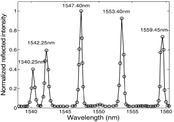
[FIG. 4.] Normalized reflected intensity versus incident angle for the fabricated input/output VHGC.
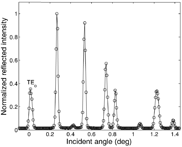
and 34.13%, respectively. This indicates that R increases as the incident-beam position shifts to the grating-waveguide boundary of the input coupler because the out-coupling effect (radiation modes) decrease, whereas the radiation modes are excited by the dephasing due to deviation from the coupling angle. However, as the incident-beam position is increased from z=2 to z=7 mm, the angular selectivity is barely changed. Therefore we are concluding that the input/output VHGC behaves as a single uniform grating, and then the angular selectivity of the input/output VHGC is mainly dependent on the effective thickness of the grating. This is because more light is diffracted from the region closer to the grating-waveguide boundaries (near zo=Lg) and the surface of the grating (near x=0), and thus the grating length Lg does not significantly affect the angular (or wavelength) selectivity [1,3]. Figure 5 shows the spectral response of the normalized reflected intensity as a function of tuning wavelength in the range between 1538.20nm to 1560.45nm for a fixed input coupling angle of a θc=0.266° and zo=5mm. As seen in Fig. 5, approximately five peak reflectance wavelengths are excited in this tuning range, and modal interference can be observed similar to that in Fig. 4 at the central wavelengths with a 1540.25nm and 1542.25nm. A measured wavelength at the FWFZ level is~0.8nm for a curve centered at 1547.4nm. Using the experimental data θc=0.266° and λc=1547.4nm in Fig. 4, we estimate approximately the FWFZ wavelength selectivity δλFWFZ=~0.74nm for a uniform single grating with a 10㎛ thickness [10]. The measured wavelength-selectivity is also slightly larger than that of the theoretical calculation as the angular selectivity. To better understand the relationship between the coupling angle and coupling wavelength in the waveguide, let us examine the experimental data in Fig. 4 and Fig. 5. If the coupling angle is tuned from the initial alignment angle θc,i to the next mode θc,i+1, then the coupling wavelength of first mode is no longer a coupling wavelength of a next mode. Therefore the wavelength should be changed to satisfy the Bragg-matching condition, the new coupling wavelength
λc,i+1 can computed from Eq. 1 to be

where we assume that ngr(λc,i)?ngr(λc,i+1) because the angular tuning is limited. The coupling wavelengths of the two adjacent modes in Fig. 5 were λc,i=1547.4° and λc,i+1=1553.4° for a fixed coupling angle θc,i=0.266°. Using these values, the corresponding coupling angle of the λc,i+1 mode is expected to be observed to be θc,i+1=~0.49° from Eq. 3. This value is roughly in accord with the measurement value of 0.533° in Fig. 4. The difference between the calculated value and the measured values is ~0.042°, and this angular difference lead to a ~1.12nm wavelength difference. Also the spacing between the central wavelengths of each mode is not perfectly coincident with the theoretical estimation of Eq. 3. Generally the analytic methods for a common uniform volume grating will not exactly match our experimental results because of the characteristics of a narrow Bragg-selectivity and a wide and thick waveguide in which few modes exist, but it is seen to be still useful to understanding and explaining approximately the behavior of our special configuration.
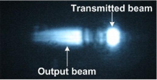
Figure 6 shows the intensity profile of the output beam coupled out from the output coupler for the incident conditions θc=0.266°, λc=1547.4nm, and zo=5mm, where the output beam is captured by using an infrared (IR) camera with a mounted zoom lens in Fig. 3. The intensity profile gradually decreases along the propagation direction z that corresponds to a uniform grating in the output coupling region as shown in Fig. 6.
In our experimental results, the measured input coupling angle and wavelength differ from the design values (θc=0°and λc=1550nm) and are primarily due to the arrangement errors in optical setups. It is obvious that precision means are necessary to fabricate an input/output VHGC to fulfill the design values within tolerance limits, and guaranteed output performance can be covered by more precise alignment, recording, and testing processes.
In this paper we have presented design and fabrication results of a surface-normal input/output VHGC operating at 1550nm wavelength region by using a 10㎛-thick DuPont photopolymer HRF600ⅹ123-10. The angular and wavelength responses of the surface-normal input/output VHGC have been investigated, showing that the input/output VHGC acts as a narrowband input/output coupler, which filters and couples only a spectrally and angularly narrow portion of the light. The angular and wavelength selectivity is mainly dependent on the effective thickness of the grating, which is consistent with the behavior of volume gratings in bulk diffraction, where thicker gratings cause narrower angular and wavelength selectivity. The output reflectance increases as the incident-beam position closes toward the grating-waveguide boundary of the input coupler, but the angular selectivity is barely changed. Our experimental results will be useful examples for understanding the behavior of the input/output VHGC embedded in a waveguide configuration and applications as the devices for integrated optics and WDM optical communications.