The LCD (Liquid Crystal Display) is the most typical example of non-emissive displays requiring an independent light source called BLU (Backlight Unit). BLU supplies LCD with homogeneous, bright, white light with appropriate color characteristics. Light sources in BLU generate visible light while other optical components diffuse, homogenize and collimate the generated light [1]. The importance of BLU technology has been increased recently because of its key role in the innovation of LCD, in particular, its largesize applications. Recent large-size LCD TV's adopt not only direct-lit but also edge-lit LED(light emitting diode) backlights the latter making the TV much slimmer and lighter along with reducing power consumption [2-3]. Moreover, dynamic driving of BLU may be adopted to improve the picture quality of LCD substantially.
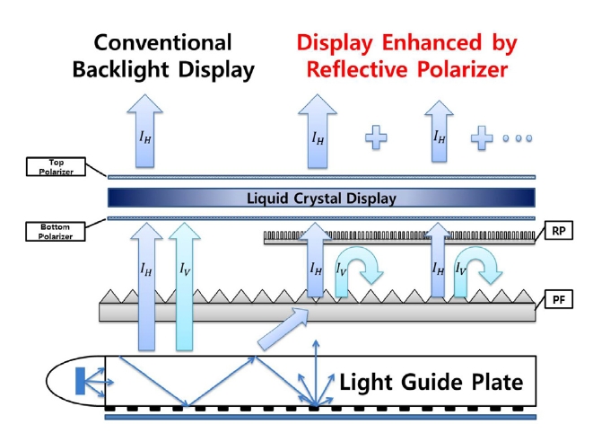
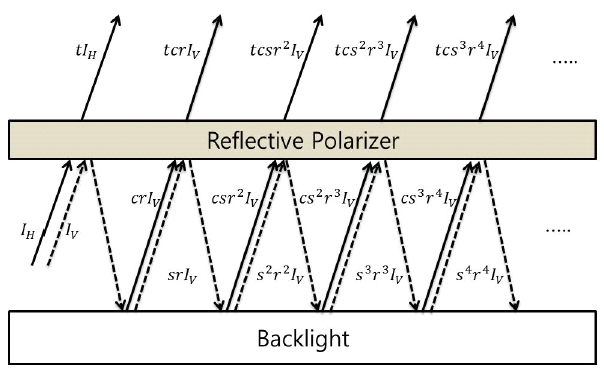
The transmission of LCD is usually less than 10%, which means the luminance of BLU should be at least 10 times higher than the panel luminance. The power consumption of TVs should be minimized to satisfy energy regulation policy. This requires that highly-efficient optical films be used to maximize the utilization of visible light generated from light sources. The most representative brightness enhancement films are collimation films and reflective polarizers (RPs). Collimation films such as prism films and micro-lens films refract the incident light toward the normal direction resulting in the increase in the on-axis luminance at the expanse of high-angle luminance values [4,5]. On the other hand, RPs reflect the light having the polarization component orthogonal to that parallel to the transmission axis of the bottom polarizer of LCD [5]. Figure 1 is a schematic diagram that shows the operating principle of RPs in backlights. Let's assume that the polarization component denoted as
Several optical principles are used to make efficient RPs. Among them, birefringent multilayer films based on generalized Fresnel relations [6] have been developed and adopted in BLU. Anisotropic scattering films [7], wire grid-based polarizers (WGPs) [8], and cholesteric liquid crystal (CLC) films [9] have been studied and developed to replace the costly multi-layer films. The optical performances of the commercially-available birefringent multilayer film in several kinds of BLU have been reported in detail [10-13]. However, the optical performances of new RPs such as WGP and CLC films have not been studied in detail as a brightness enhancement films in backlights. The current study is to report the optical performances of WGP as a RP in the edge-lit BLU for the first time and to compare them with those of commercial dielectric multilayer films. The FDTD (finite difference time domain) simulation method was used to optimize and predict the optical performance of WGPs as a RP in BLU.
A 3.5-inch edge-lit BLU consisting of white LEDs, a light guide plate (LGP), a diffuser film (DF), and a prism film(PF) was used to evaluate the optical performances of a WGP. A spectroradiometer (PR670, Photo Research) was used to measure the luminance. A simple home-made rotator was used to obtain the angular dependence of the luminance on each film. In order to mimic the bottom polarizer of LCD, an absorptive sheet polarizer (AP) was put on the PF. Either a multi-layer RP (DBEF-D, 3M Co.) or a WGP (NT46-636, Edmund Optics) was inserted between PF and AP. The pitch, height, and the width of wire grids on the WGP were 144 nm, 155 nm, and 65 nm, respectively. The on-axis luminance was measured before and after inserting the RP to determine the luminance gain factor due to the polarization recycling process. On the other hand, the con-
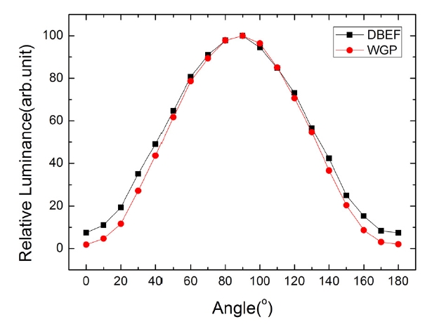
trast ratio of each RP was obtained by rotating the transmission axis of the AP put over the RP. Figure 2 shows the angular dependence of the luminance on the rotation angle of the AP. 90o indicates the condition that the transmission axis of the RP is parallel to that of the AP. The contrast ratios of DBEF and WGP were about 13 and 52, respectively.
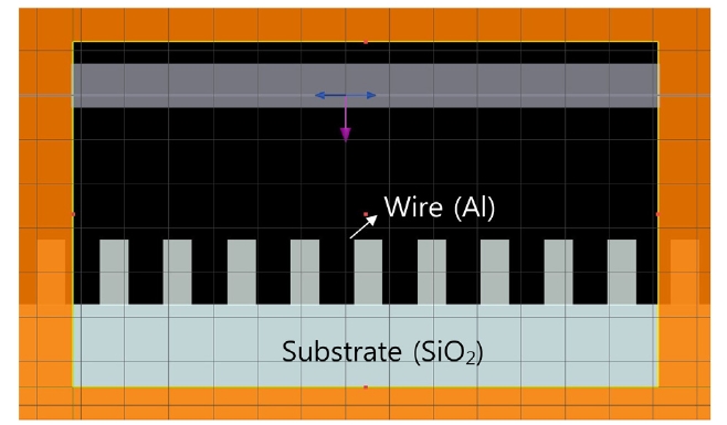
The FDTD Solution software (Ver.7.5, Lumerical Co.) was used to simulate the optical performances of WGP. This method is a time domain technique by which the electric and magnetic fields can be calculated as a function of time based on the Maxwell equations. The frequency information is obtained via Fourier transformation during the simulation. The simulation was carried out in a twodimensional space. The pitch, the width and the height of the grids were changed systematically to investigate the dependence of the optical performances such as transmission on the geometrical parameters of WGP. Figure 3 shows one example of the constructed WGP with a width of 65 nm, a height of 155 nm and a period of 144 nm, which are the dimensions of metal wires formed in the experimental WGP. The materials for the metal wire and the substrate were aluminum and SiO2 glass, respectively. A plane wave at a specific wavelength and a specific polarization state in the visible range was used to investigate its transmission and reflection behaviors depending on the polarization.
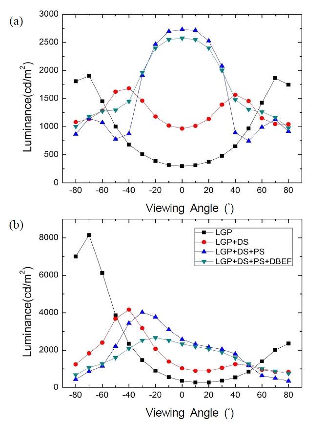
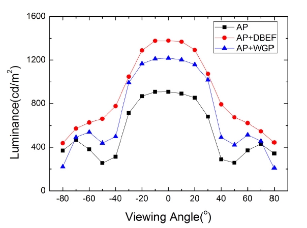
Figures 4 (a) and (b) show the luminance distributions on LGP, LGP+DF, LGP+DF+PF, and LGP+DF+PF+RF (DBEF) along the horizontal and vertical directions, respectively. The experimental results in this figure are very typical in edge-lit BLUs. The light tends to escape toward high-angle directions on LGP due to the specular reflection component of the scattering dots printed on the bottom surface of LGP. These oblique rays are redirected toward the normal direction via DF and PF. Figure 5 shows three angular distributions of the luminance on AP, AP+DBEF and AP+WGP, all of which were installed on LGP+DF +PF. The luminance value on AP can be considered to be proportional to the amount of the light that passes through
the bottom polarizer of the LCD panel. This corresponds to the
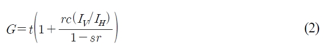
A phenomenological model [5] can be used to evaluate the detailed performances of RP [11-13]. Figure 6 shows a schematic figure of this model. According to this model, the incident, unpolarized light (
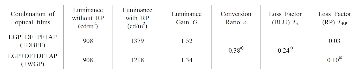
Luminance values on an absorptive polarizer that was placed on two types of reflective polarizers(RPs), i.e., DBEF or WGP, in an edge-lit backlight. The transmission axis of the absorptive polarizer was set to be parallel to that of RP. The gain factor G, the conversion ratio c, and the loss factor Lc and LRP of the backlight and RP, respectively, are also shown in the table
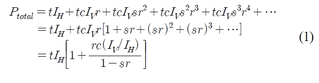
According to this equation, the power gain (and thus luminance gain) factor
The ratio
In order to determine the value of
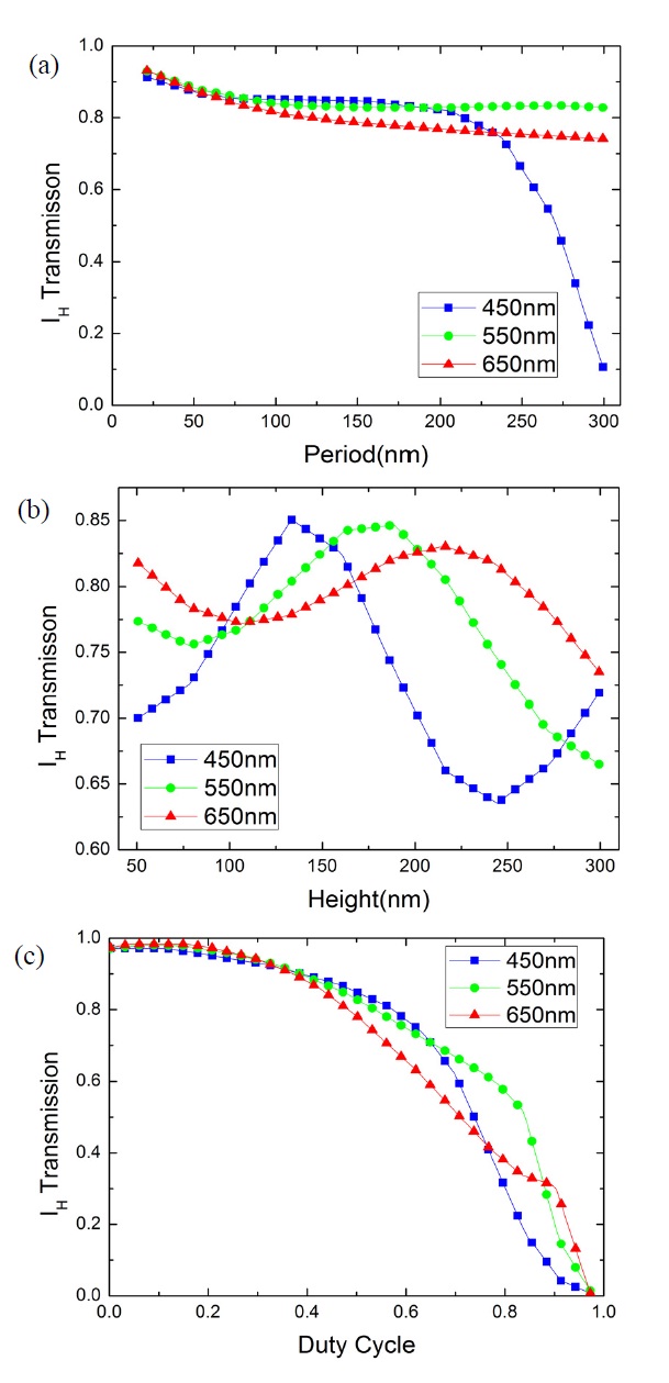
The most important parameters that determine the optical performance of WGP are the period(=pitch), height, and duty cycle(the width divided by the pitch) of metal wires. Nanoimprint lithography is usually used to fabricate nano- WGPs for the purpose of polarization manipulation [8]. Figures 7 (a), (b) and (c) are the dependences of the transmission of IH polarization on the period, height and duty cycle, respectively, at three wavelengths in the visible range. Fig. 7(a) shows that the transmission of
144 nm, indicating energy efficiency will be increased with smaller width if the period is fixed. The duty cycle of 0.5 means that the wire width is 72 nm, i.e., half the period of 144 nm. The minimum allowed duty cycle will also be limited by the manufacturing process. These simulation results are consistent with previous studies [8,14].
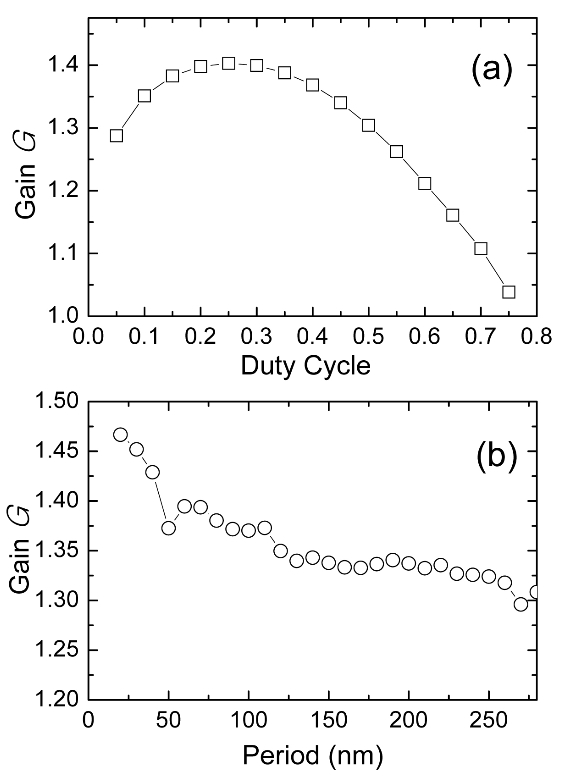
Based on these simulation results, the best performance of WGP as a reflective polarizer in the backlight can be discussed. For this purpose, the height was fixed to the experimental value of 155 nm, and the width (i.e., duty cycle) or the period was changed to investigate the dependence of the luminance gain
length of 550 nm. The optimum duty ratio for the maximum gain is 0.25 at which the luminance gain is about 1.4 and the wire width is ~ 36 nm. On the other hand,
The optical performances of WGP were investigated for backlight applications as a reflective polarizer by experiment and the time-domain simulation method. The results were compared with those of DBEF, the commercial dielectric multilayer film. The contrast ratio of WGP was higher than that of DBEF, while its luminance gain factor was lower than DBEF by 18%. The light loss factors of DBEF and WGP were approximately 0.03 and 0.10, respectively, which were obtained by combining the experimental results and FDTD-based simulation. This was attributed to the higher internal loss in metal wires of WGP because of the light absorption via dissipation processes. The period and the width of metal wires comprising WGP were optimized by the FDTD simulation, and the luminance gain factor was found to increase to about 1.47 at the condition of period of 20 nm at the duty cycle of 0.45 and the height of 155 nm.


![A schematic figure showing the operating principle of reflective polarizers [5]. Regarding the meaning of symbols, see the text.](http://oak.go.kr/repository/journal/11470/E1OSAB_2012_v16n2_151_f006.jpg)