An off-axis four-mirror-anastigmatic telescope is presented here which is composed of two aspheric surfaces and two spherical surfaces. The entrance pupil diameter is 290 mm and the stop is located at the primary mirror. The effective focal length is 900 mm. The strip field of view for the telescope is 15° × 0.2° and if the telescope is launched into an orbit about 400 km altitude, the observed range width will be more than 105 km within a scene without any other auxiliary scanning instrument. The spectral range can be as wide as from visual wave band to infrared wave band in the mirror system. This telescope can be used for environmental monitoring with different detectors whose pixel is adapted to the optical resolution. In this paper, the spectral range is chosen as 3.0 -5.0 μm, and center distance of the pixel is 30 μm. And the image quality is near the diffraction limit.
Recently, due to the rapid development of remote sensing, reflective telescopes are widely used, since large dimension optical refractive material is not required in the telescopes; and there are no chromatic aberrations in the optical path. The field of view (FOV) is small in the two-mirror optical telescopes, for example, the FOV for the Ritchey-Chretien optical system which has largest FOV is only a few minutes [1]. Though the catadioptric telescope can give a much larger FOV as 2.3° in STSAT3 [2], the refractive material for the telescope is also large especially when the telescope configuration is used as a high resolution remote sensing instrument. FOV is as wide as 10° in the reflective Schmidt telescope, but it has a very large configuration [3,4]. The off-axis three-mirror-anastigmatic (TMA) telescope can give a wider FOV and a more compact configuration [5,6], but the off-axis TMA telescope is difficult to achieve because of three aspheric mirrors, especially for off-axis TMA telescope with strip FOV wider than 10°.
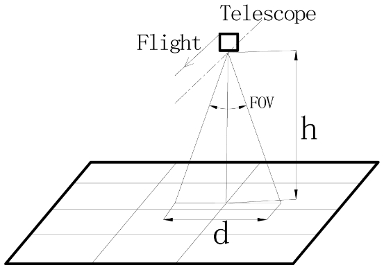
With the development of space optical remote sensing, the wider spectral range and the wider FOV are pursued. Wider spectral range in the telescope can provide more information from the interested targets, wider FOV can provide wider range in the object space without any other auxiliary scanning instrument since the width is given by equation 1.

where h is the altitude of the telescope to earth. When h is not changed, the wider FOV, the larger d, then the function of the telescope will be improved. The geometric relationship about d, h and FOV is shown in Fig. 1.
When the FOV is very big such as more than 10°, then the apertures for high resolution reflective telescope (long focal length and large entrance pupil) will be larger and the difficulties for aspheric mirror fabrication will be sharply
increased. In order to achieve a telescope with high resolution, wide FOV, and easy manufacturing, an off-axis four-mirroranastigmatic (FMA) telescope with 290 mm entrance pupil was designed which is composed of two aspheric mirrors and two spherical mirrors. And the stop is located at the primary mirror. The strip FOV for the telescope is 15° × 0.2° and the effect focal length is 900 mm.
II. OPTICAL DESIGN OF OFF-AXIS FOUR-MIRROR-ANASTIGMATIC TELESCOPE
2.1. Optical Design Requirements
There should be no obscuration in the optical path in order to improve the optical MTF (Modulate Transfer Function). Then the off-axis mode will be taken. In the telescope, the field of view is tilted about the X axis (which is perpendicular to the optical axis, and the Cartesian coordinates shown in Fig. 2), and the stop is located at the primary mirror.
In order to detect the environmental targets whose irradiance can pass through the atmosphere, the spectral range is chosen as 3.0 -5.0 μm. In the optical designing process, the diffraction effect should be of concern since the detectors can be chose scientifically in order to collect more energy from instant FOV by every pixel. The radius of Airy disk can be deduced by equation 2.
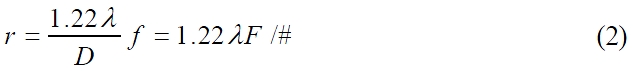
Where λ is the primary wavelength, D is the entrance pupil diameter, f is the focal length of telescope, and F/# is the number of f/D. In this telescope, the primary wavelength λ= 4 μm, the F/# = 900/290 = 3.1, so that the radius of the Airy disk r=15.145 μm, then the diameter of the Airy disk is 30.29 μm. And center distance of the pixel is 30 μm in the detector, so that most of the energy within an instant FOV can be collected by each pixel. Then the instant FOV can be deduced by the equation 3.
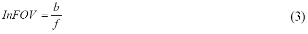
Where b is the center distance of the pixel, f is the focal length of the telescope. Then the angular resolution is 33.3 × 10⁻⁶ radian, the ground sample distance (GSD) is about 13.33 m on the earth’s surface when the altitude is 400 km. Since the FOV is 15° × 0.2°, then the focal plane of the detector is about 7850 × 100 pixels. When the altitude is 400 km and the push-broom mode is used, the area on the earth’s surface is about 105 km × 1.39 km within a scene.
In order to get wider FOV and decrease the manufacturing difficulty, we can increase a mirror to the TMA telescope to redistribute the power as
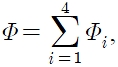
where
In order to remove the obscuration in the telescope, two methods can be taken:
(1) Make the incident beam tilt and propagate to the telescope in the Cartesian coordinates;
(2) Make the entrance pupil be off-axis in the Cartesian coordinates.
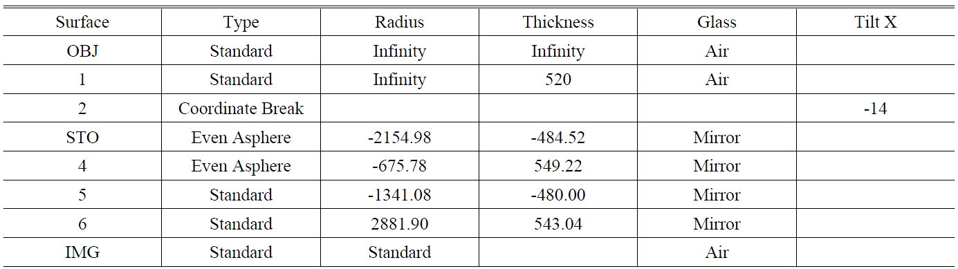
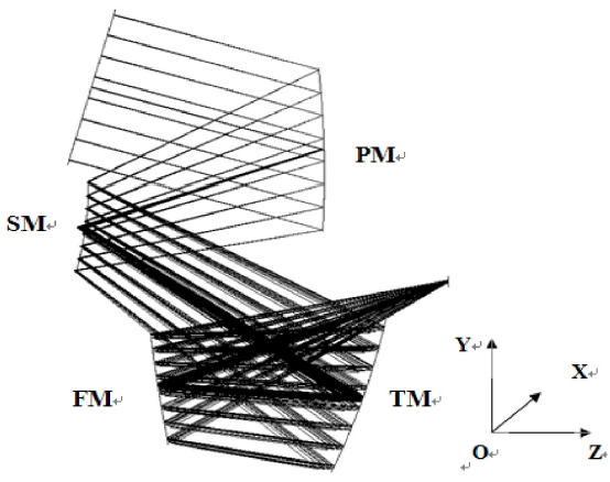
The telescope is designed as off-axis FMA telescope, which is composed of two aspheric mirror and two spherical mirrors. In the telescope, the primary mirror (PM) is a symmetric concave aspheric mirror, the secondary mirror (SM) is a deviated (along the Y axis which is perpendicular to optical axis, and the Cartesian coordinates shown in Fig. 2) convex aspheric mirror, and the third mirror (TM) and the fourth mirror (FM) are all concave spherical mirrors. The entrance pupil is located at the PM. The optical configuration of the off-axis FMA telescope is shown as Fig. 2, the lens data is shown in Table 1 from ZEMAX
[TABLE 1.] Lens data from ZEMAX (unit: thickness/distance in mm, angle in deg.)

Lens data from ZEMAX (unit: thickness/distance in mm, angle in deg.)

Parameters for PM
lens data format.
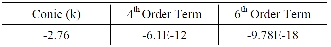
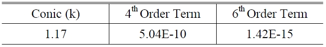
In this paper, the PM and SM are all even aspheric surfaces, and the surface sag is shown as equation 4.

Where c is the curvature (the reciprocal of the radius), r is the radial coordinate in lens unit, k is the conic constant, and
The even aspheric surface parameters for PM and SM are shown in Table 2 and Table 3.
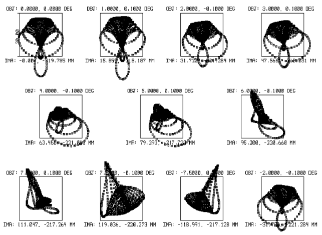
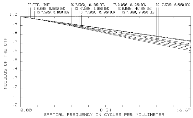
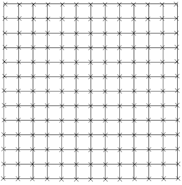
The image quality is evaluated by Spot Diagram, Optical MTF and Grid Distortion as shown in Fig 3, Fig 4 and Fig. 5. The maximum RMS radius of the spot diagram is 10.882 μm, when the pixel is 30 μm× 30 μm. At the Nyquist frequency (16.67 lines per millimeter), the minimum MTF
Parameters for SM
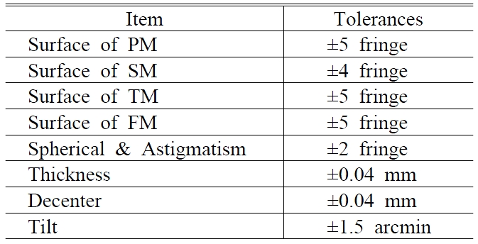
[TABLE 4.] Optical tolerances for manufacturing

Optical tolerances for manufacturing
for the telescope is 0.623. The maximum distortion is -1.0237%. The image quality is good enough for the remote sensing application.
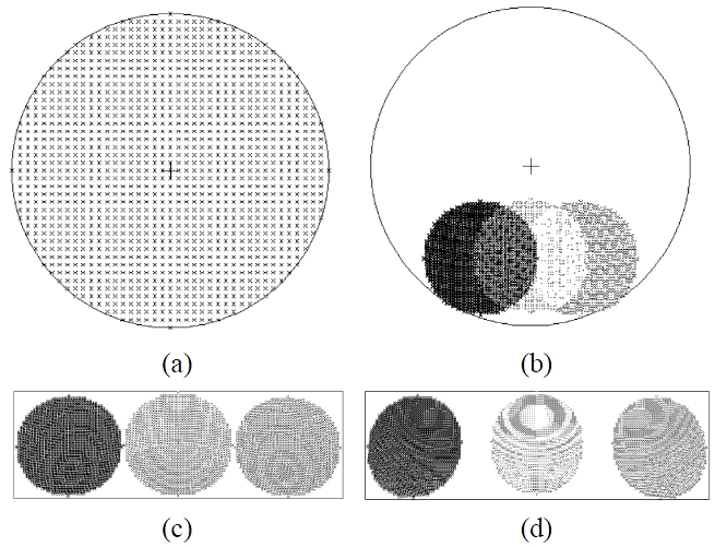
The ray footprints of each mirror are shown as Fig. 6. The ray footprints for PM are shown in Fig. 6(a), it shows that the PM is a symmetric mirror so that the difficulty of fabrication can be decreased compared to the off-axis one. The ray footprints for SM are shown in Fig. 6(b), it shows that the convex mirror used in the optical path is deviated along the Y axis. Since TM and FM are spherical mirrors, they do not have a symmetric optical axis as the aspheric mirror, and then we do not care for their distances deviated along Y axis. The ray footprints for TM and FM are shown in Fig. 6(c) and Fig. 6(d).
2.3. The Optical Tolerances for Manufacturing
Just the manufacturing errors concerned, the optical tolerances are shown in Table 4, and the RMS radius for spot diagrams will be changed at most 2.1 μm with Mont Carlo calculations in the ZEMAX program. From Table 4, we can conclude that the tolerances are loose.
An optical design of off-axis FMA (four-mirror-anastigmatic) telescope (f/3.1) is presented in this paper. The telescope is composed of two aspheric mirrors and two spherical mirrors. The PM is a symmetric concave aspheric mirror, SM is a convex aspheric mirror, and TM and FM are all concave spherical mirrors. With spectral range 3.0 -5.0 μm, the image quality is near diffraction limited. The strip FOV is 15° × 0.2°. From the altitude of 400 km, the FMA telescope can take a scene of 105 km × 1.39 km without any scanning instrument while the GSD is 13.33 m.