Daylighting has a very effective role in reducing power consumption and improving indoor environments in office buildings. Previously, it was not under consideration as a major source of renewable energy due to poor reliability in the design. Optical fiber as a transmission medium in the daylighting system demands uniform distribution of light to solve cost, heat, and efficiency issues. Therefore, this study focuses on the uniform distribution of sunlight through the fiber bundle and to the interior of the building. To this end, two efficient approaches for the fiber-based daylighting system are presented. The first approach consists of a parabolic mirror, and the second approach contains a Fresnel lens. Sunlight is captured, guided, and distributed through the concentrator, optical fibers, and lenses, respectively. At the capturing stage, uniform illumination solves the heat problem, which has critical importance in making the system cost-effective by introducing plastic optical fibers. The efficiency of the system is increased by collimated light, which helps to insert maximum light into the optical fibers. Furthermore, we find that the hybrid system of combining sunlight and light emitting diode light gives better illumination levels than that of traditional lighting systems. Simulation and experimental results have shown that the efficiency of the system is better than previous fiber-based daylighting systems.
There has been high demand to increase the energy produced from renewable energy systems to reduce the emissions of greenhouse gasses. Solar energy is one of the main sources of electricity production, and it can be used for thermal applications and for daylighting. The main sources of power consumption and greenhouse gas emission in the world are buildings. Power consumption due to electric lighting in buildings is becoming a critical problem, using 40-50% of total energy [1]. Daylighting is a part of the answer to this issue.
Daylighting has a significant role in the field of renewable energy. It allows for reduced power consumption in sustainable developments. The development of an appropriate and efficient sunlight collecting and distributing system will lead us to a solution to the energy problem, which is becoming increasingly serious. Efficient daylight buildings are estimated to reduce electric lighting energy consumption by 50-80% [2].
While office buildings usually have windows on each floor, light from the windows varies according to the position of the sun and interior areas may not have sun exposure. As a result, the lighting is not consistent and some areas may remain dark. Another lighting source is needed to illuminate these regions. Therefore, we shall deliver daylight uniformly at those areas of the building through our proposed daylighting system.
The research on office buildings indicates the failure to provide comfortable indoor environments. One of the reasons is the use of artificial light instead of sunlight. Most office workers spend their days indoors under artificial light. As a result, 78 million have calcium deficiency due to insufficient vitamin D, and 15% of office workers complain of eye strain under artificial light [3]. Sunlight has positive effects on the human body because it provides a sense of cheerfulness, and it can be used to reduce seasonal affective disorder and other illnesses [3]. The eyes and skin absorb non-visible ultraviolet wavelengths that are needed to stimulate the neuroendocrine system and to synthesize the production of vitamin D3. Low levels of vitamin D have been shown to increase the risk of strokes and heart attacks by 60% [4]. Research clearly shows that daylight improves the quality of life and saves electric lighting energy consumption. Thus, daylighting systems are highly acceptable for office buildings.
Different architectural designs introduce windows and other open areas to illuminate buildings. Most of these buildings are constructed by considering the daylight factor (DF) to reduce the use of electric lighting. The DF is written as [5]
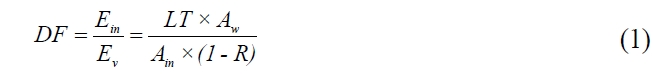
where
Previously, daylighting systems were not discussed as a major topic. One reason for this is that most of the solar concentrators were developed for photovoltaic power generation and thermal applications [7, 8]. While numerous daylighting systems have been demonstrated with light pipes [9-11] and optical fibers [12-21], most of the designs have a large number of tracking reflectors and lenses and, thus, require an adequate area to be installed.
The proposed system is expandable and has only one tracking module. The currently available fiber-based system is the Himawari solar lighting system [15]. It has two series of models with a different numbers of lenses and optical fibers. The system contains quartz-glass optical fiber, which makes the system expensive. However, the goal is to get high illumination deep into the building at a low cost.
Usually, daylighting systems are mounted on the roofs of buildings. The core daylighting system was demonstrated and installed above the window and near the ceiling region [9]. However, there are some drawbacks to installing a daylighting system near a window (e.g., reduction of daylight from the window and difficult installation due to different structural designs of the buildings). Our system can be placed anywhere in the free region of the building. It is also better for solar energy systems to direct uniform light to solar cells in the basement.
The main purpose of this study is to deliver uniform daylight to the interior through optical fibers. For this purpose, a parabolic mirror and Fresnel lens were preferred. To make the system cost-effective, plastic optical fibers (POFs) were used. They are very sensitive to heat; therefore, the heat effect is reduced by uniform and collimated light. Furthermore, a hybrid system gives better illumination quality. This research will improve the efficiency of the optical fiber-based system.
Size is a critical issue in the daylighting system. In order to install it over different free regions of the building (e.g., roof), the system should occupy a small area with an effective output and adapt to the surrounding environment according to the required size. The size of the indoor and outdoor modules is selected according to the required range of illumination. Normally, a large collecting system is preferred to capture more sunlight and the indoor apparatus would be smaller than the outdoor apparatus.
The light collecting system must capture the sunlight and then focus it over the small area. Previously, daylight collecting systems were developed using different concentrators. In some cases, large numbers of reflectors or lenses were utilized to illuminate the receiver (bundle of optical fibers); however, increasing the amount of reflectors or lenses is costly. Generally, systems are made with a minimum number of modules for cost effectiveness. In case of non-uniformity, each optical fiber will have a different intensity of light. This produces heat and reduces the efficiency of the system. Therefore, the purpose of this study is to achieve uniform daylight at the destination at a low cost.
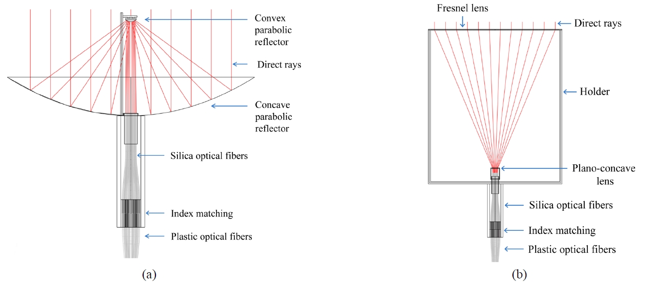
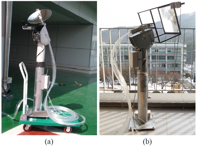
The idea behind the system is to capture sunlight and then focus it over a small area. The light is guided through light pipe or fibers and distributed at the building’s interior. For daylighting systems, uniform illumination is mandatory at the capturing and distributing stages. The sunlight capturing system using a parabolic mirror is shown in Fig. 1(a). A parabolic mirror captures sunlight and directs the light towards a second mirror, which illuminates the bundle of optical fibers. The design using a Fresnel lens is shown in Fig. 1(b). Direct sunlight is focused by the Fresnel lens. The light goes through a collimating lens and then the uniform light illuminates the bundle of optical fibers.
III. UNIFORM AND COLLIMATED ILLUMINATION
We proposed two efficient approaches to get collimated light, with a parabolic mirror and Fresnel lens. The bundle of optical fibers was illuminated uniformly with both approaches.
The parabolic mirror had a small f-ratio and large aperture area to maximize the sunlight captured, and it had
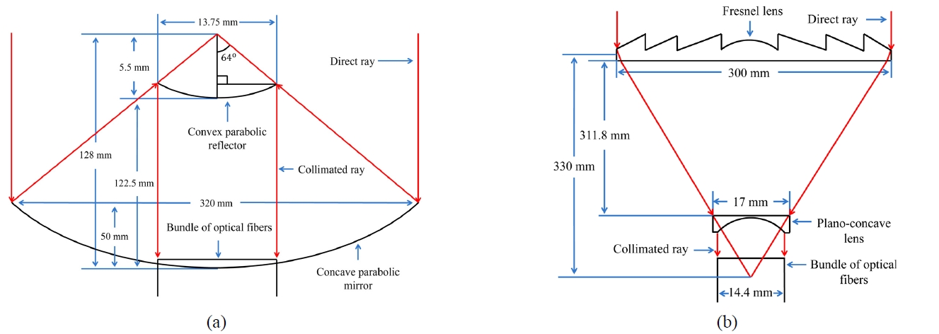
a high concentration ratio. Concave and convex parabolic reflectors were appropriate to produce collimated light, as shown in Fig. 2(a). Maximum sunlight was exposed to the bundle of optical fibers by arranging the fibers in a circular shape. Correct placement and measurements of reflectors to make collimated light were achieved by

where

where
A Fresnel lens with a constant pitch of 0.5 mm was used. If we increased the size of the Fresnel lens, with its constant pitch, we would get lower efficiency due to blockage of the light. If we increased the diameter of the parabolic mirror, we would achieve higher efficiency due to the larger reflective surface area. Therefore, it can be concluded that a parabolic mirror is more efficient than a Fresnel lens, while a Fresnel lens gives good performance at a low cost.
The effective focal length (EFL) of the Fresnel lens was calculated by

where

where

where
Optical fibers have many advantages in the daylighting system (e.g., highly acceptable for wiring and the best source of transmission of light). Typically, optical fiber is produced from different materials (e.g., glass and plastic). Silica optical fiber (SOF) is known as a good light transmission media, but it is expensive. Mostly, plastic optical fiber (POF) is preferred in the daylighting system due to low-cost, flexibility, strength, and acceptability for complex wiring in the building. Particularly, they have a bending radius of a few centimeters. POF has a large core diameter to transmit a large amount of light by efficient total internal reflection (TIR). The loss at the input end of the fiber is sometime called Fresnel loss and can be calculated by [23]
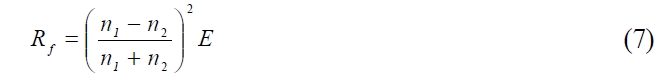
where
V. SOLUTION OF THE HEAT PROBLEM
Sunlight includes different wavelengths of light (e.g.,
ultraviolet, visible, and infrared) which produce high temperature when focused over a small area. Previously, POF was not used in the daylighting system due to the heat problem because POF is highly sensitive to heat. The heat problem needs to be solved before POF can be used for daylighting. We performed experiments by changing the size of the parabolic mirror and the Fresnel lens and by varying the number of optical fibers in the bundle. Bundles of fifty-five optical fibers for the parabolic mirror and the Fresnel lens were found appropriate. However, since one fiber in the bundle of parabolic design was shadowed by the supporting rod, we were able to reduce the number of optical fibers in the bundle from fifty five to fifty four.
The presented model was particularly suitable to obtain the required range of illumination. When we used the mentioned fiber bundle and increased the size of the capturing module, the optical fibers eventually started to melt. On the other hand, when we decreased the size of the capturing module while using the predefined fiber bundle, the light intensity decreased, which affected the efficiency of the system. Therefore, better efficiency and elimination of the heat problem was achieved by the presented measurements. The same applied to the bundle of optical fibers. Decreasing or increasing the number of fibers in the bundle for the mentioned concentrators did not give a better performance.
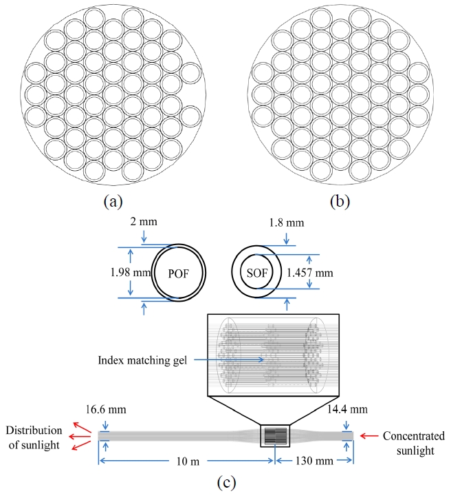
Another problem was solved by introducing SOFs before POFs. For example, if the system is moved to another place, that has a high intensity of light above the defined
limit, some heat will be absorbed by the SOFs. The core diameters of SOF and POF are 1.457 mm and 1.98 mm, respectively. Here, sunlight entered from a small opening to a large opening; therefore, there was very little loss. Furthermore, index matching gel was applied between the SOFs and POFs to minimize the loss that can occur due to the air gap between them. Overall, the proposed approaches helped to reduce the heat effect and to increase the efficiency of the fiber-based system.
VI. DISTRIBUTION OF SUNLIGHT AT THE INTERIOR
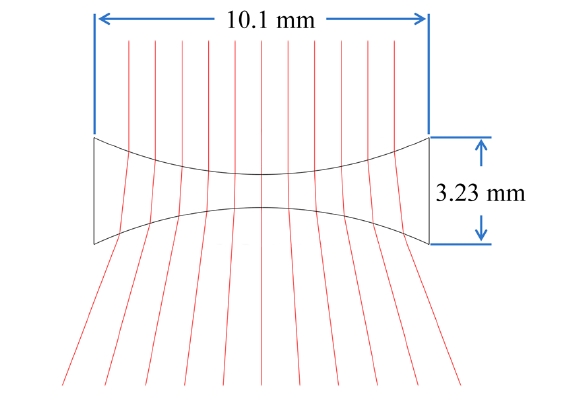
The distribution of uniform light is becoming a critical issue in solid-state lighting. Similarly, this issue is becoming increasingly serious in the daylighting system. In our case, we had a light source (the bundle of optical fibers) of small size with a high beam of light. To spread the light at the destination, the optical fibers were divided into different bundles, and the fibers in each bundle were organized into a circular shape, which covered a surface area of 78.54 mm2. A diverging lens was mounted at the end of each bundle. A biconcave lens was selected to diverge the incoming light from the optical fibers, as illustrated in Fig. 4.
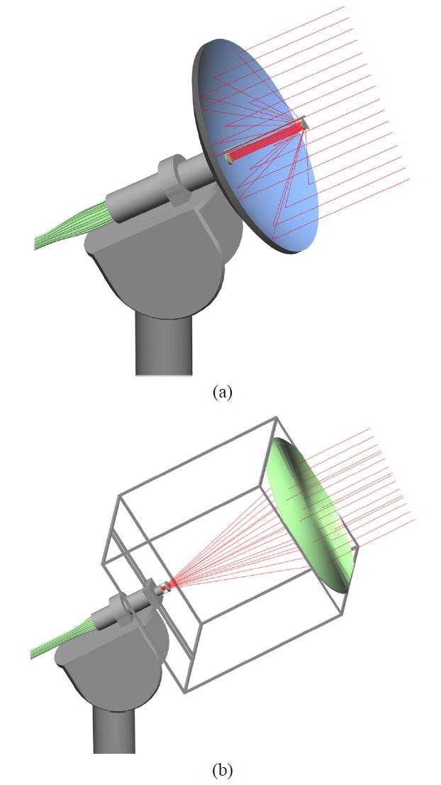
LightToolsTM was used to implement the proposed daylighting system, as shown in Fig. 5. In the simulation, a real time environment was generated by designing each part and considering each loss. The source, receiver, reflectors, lenses, bending fibers, index-matching, and other hardware modules were designed in the software. In the simulation, the length of the POF and SOF was considered the same as that of the real time hardware mentioned in Section IV. The optical fibers were arranged in a circular
shape to reduce the spacing between the fibers. In the bundle of optical fibers, we tried to make the region that has shadow due to the supporting rod empty.
For daylight, lumens was calculated to simulate the entire optical design for indoor by [23]

where
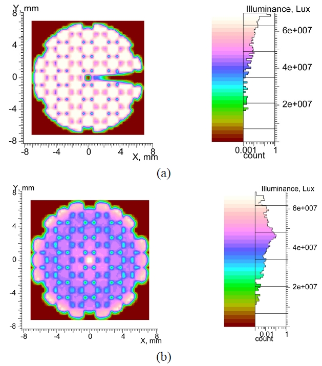
The light source in the simulation for both approaches had different flux values, which were calculated according to the surface area of the concentrator. The system was illuminated by inserting average illuminance of 100 Klx, and the illuminance was measured at the fiber’s end. As evident from Fig. 6, uniform illumination was achieved in the bundle of optical fibers, and each optical fiber had similar illuminance.
In Fig. 6 (a), there are two dark regions due to the shadow of a supporting rod and convex reflector. When
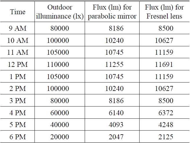
Average illuminance at different times of the day and calculated flux for each concentrator
direct sunlight hit the convex reflector, it was absorbed and produced shadow at the center of the concentrator, where the fiber bundle was mounted. Thus, the light was not reflected from the central region of the concentrator, which produced the shadow at the center of the fiber bundle. This shadow covered a very small region, because we used a small convex reflector.
The other dark region was produced by the supporting rod on the right-hand side, since some light reflected from the concentrator was absorbed by the rod. To reduce this shadow, we used a very thin supporting rod to support the convex reflector. The optical fibers were arranged in the circular shape, because the light reflected from the convex reflector formed a circular shape. The amount of the optical fibers in the fiber bundle for the mentioned concentrator was selected to reduce the heat problem explained in Section V. Here, since the dark region by the supporting rod was too low to use, we found it was quite appropriate even if we eliminated the fiber on that region. And it had reduced the cost of the bundle.
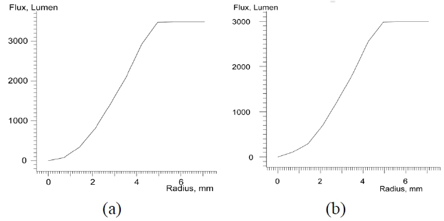
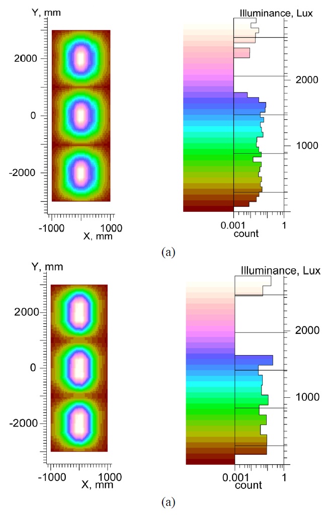
To distribute daylight at the destination, fibers were arranged into three bundles and then placed at different positions to cover a surface area of 12 m2. Our main goal was to illuminate a large area with an average illuminance of more than 500 lx. To use small biconcave lenses for the distribution of light, optical fibers in each bundle were organized to form a circular shape. The amount of power collected in the aperture of the fiber bundle can be expressed by the encircled energy graph, as shown in Fig 7. At the interior, the illuminance was measured at 2 m below the roof of the room, as shown in Fig. 8. The average illuminance values for the parabolic mirror and the Fresnel lens were 705 lx and 675 lx, respectively. An office building is required to achieve an average illuminance of 500 lx [24]. We have accomplished this required illuminance value by using both approaches.
Recently, there has been an increase in the use of light emitting diodes (LEDs) in buildings to consume less power [25]. To attain the required illuminance of 500 lx in the office when sunlight fell from the required range, we
made use of LED sources. If illuminance of the daylight decreased from a specific limit, LEDs were turned on automatically to meet the deficiency.
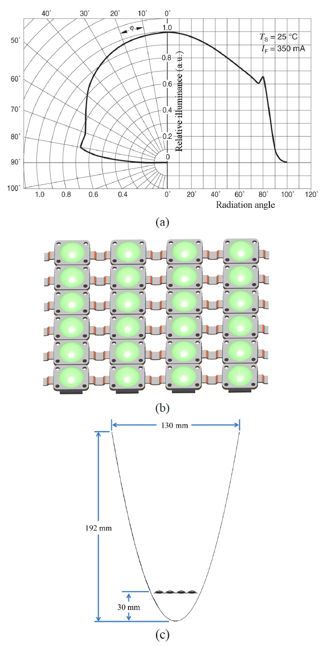
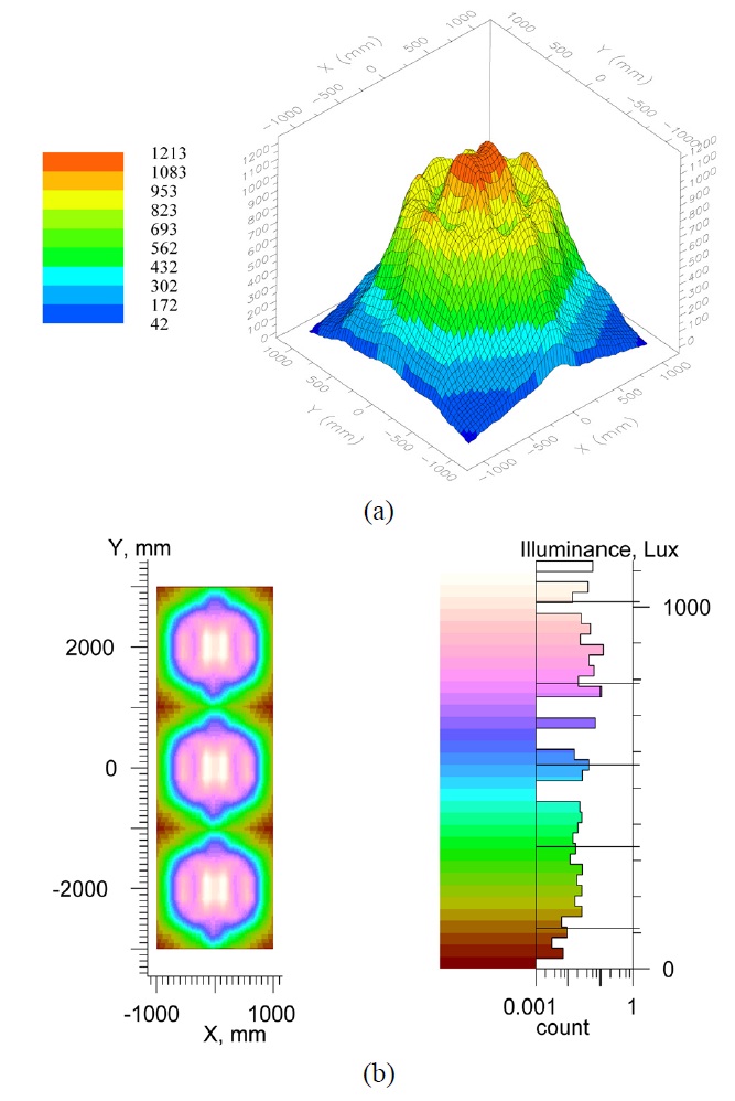
Electric lighting control is essential for a daylighting system to save power and to deliver artificial light in case of the non-availability of daylight. Therefore, it is necessary to make a hybrid system. In our study, photocells sensed the available light, and the control algorithm maintained an average illuminance of 500 lx. OSRAMTM LW-W5AM LEDs were used, which have the maximum optical efficiency of 130 lm/W. The candle power distribution curve of the LED is shown in Fig. 9(a) [26]. As shown in Fig. 9(b), 24 LEDs were arranged to make a single source of light, which illuminated an area of 4 m2. A parabolic reflector was used to focus the light at the required area, as illustrated in Fig. 9(c). An average illuminance of 537 lx was achieved from the LEDs (Fig. 10). The LEDs illuminance distribution was made similar to the daylight distribution to decrease the changing effect.
Hardware designs for both approaches were developed to verify the proposed system (Fig. 11). We used the parabolic mirror and Fresnel lens due to their availability and ease of use in the manufacturing process. The efficiency of the system depended on tracking the sun. Therefore, it was compulsory for the daylighting system to have a sun tracking device that rotated the light collecting modules towards the sun. To this end, a two-axis sun tracking module was installed to capture direct sunlight at all times of the day.
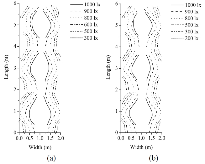
Different experiments were conducted to measure illuminance levels in the room. To show illuminance distribution at the interior of the building, we used only one input
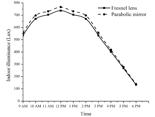
illuminance value, which is 100 Klx for the simulation and the real experiment. In Fig. 12, we show the real time measured illuminance distribution at the interior of the building, which is almost similar to the achieved distribution from the simulation (Fig. 8). The average illuminance values were calculated at different times of the day with both approaches (Fig. 13), where the parabolic mirror gave higher illuminance values than did the Fresnel lens. In the simulation, we calculated the average illuminance value at 100 Klx (Fig. 8), which was similar to the achieved illuminance value at 10 AM in the real experiment (Fig. 13). The study also demonstrated that high illumination levels can be achieved at the interior of the building via a large sunlight collecting system, and the number of optical fibers in the bundle should be selected according to the surface area of the concentrator. Finally, it was concluded that the proposed daylighting system can illuminate different regions of the building uniformly through optical fibers.
We have demonstrated that the optical fiber-based daylighting system can be used to illuminate office buildings uniformly. This study successfully presented two efficient approaches to increase the efficiency of the system. It has been verified from simulation and real experiments that the bundle of optical fibers can be illuminated uniformly to achieve the same intensity of light in each fiber while reducing the heat problem. Therefore, it is possible to deliver uniform daylight to different regions of the building. The efficiency of the system was increased by collimated illumination and by minimizing the shadow due to convex reflector and mechanical parts. As a result, a high intensity of light was attained.
An electric lighting control system complements daylighting in reducing power consumption in buildings which are the main sources of greenhouse gas emission and power consumption. We found that a hybrid system combining sunlight and LEDs gave better illumination quality. The proposed system guarantees to save electric lighting power consumption by delivering an average illuminance of more than 500 lx at all times.
In the future, we will improve the uniformity of light at the building’s interior by introducing a combination of lenses at the end of each fiber bundle. Daylight can also be distributed into the building through light guides, where light will be inserted into the light guide through optical fibers.