An off-axis integral floating system using a concave mirror is analyzed to resolve the image distortion incurred by the off-axis optical arrangement. The concave mirror can be adopted as the floating device to improve the optical efficiency. The image distortion due to the tilting axis of the concave mirror needs to be analyzed precisely to generate the pre-distortion image. In this paper, we calculate the image deformation in the off-axis structure of the concave mirror using the geometrical optics. Using the calculation results, the compensated elemental image can be generated for the pre-distortion integrated image, which can be projected to the floating 3D image without image distortion. The basic experiments of the off-axis integral floating are presented to prove and verify the proposal.
Integral imaging is one of the emerging auto-stereoscopic three-dimensional (3D) display techniques, which reconstructs a 3D image to integrate the elemental image through a lens array or pin-hole array [1-4]. The elemental image is composed of the arrayed 2D images which have the directional information of the 3D object. The integral imaging system can express the full parallax and the various depth 3D images which, however, have the limitations of the expressible depth range and the viewing angle. Recently, many techniques have been researched and reported to enhance the 3D image quality of the integral imaging display [5-11]. Moreover, many integral-imaging-based techniques have also been studied to inherit the merits of the integral imaging.
Integral floating is one of the techniques based on the integral imaging [12-17]. The integral floating employs the additional large aperture floating device in front of the integral imaging system, which can enhance the 3D image quality such as the improved depth range, the reduced seam noises from the lens array, and the increased viewing area. However, the general large aperture device is difficult to manufacture and often results in the image distortion.
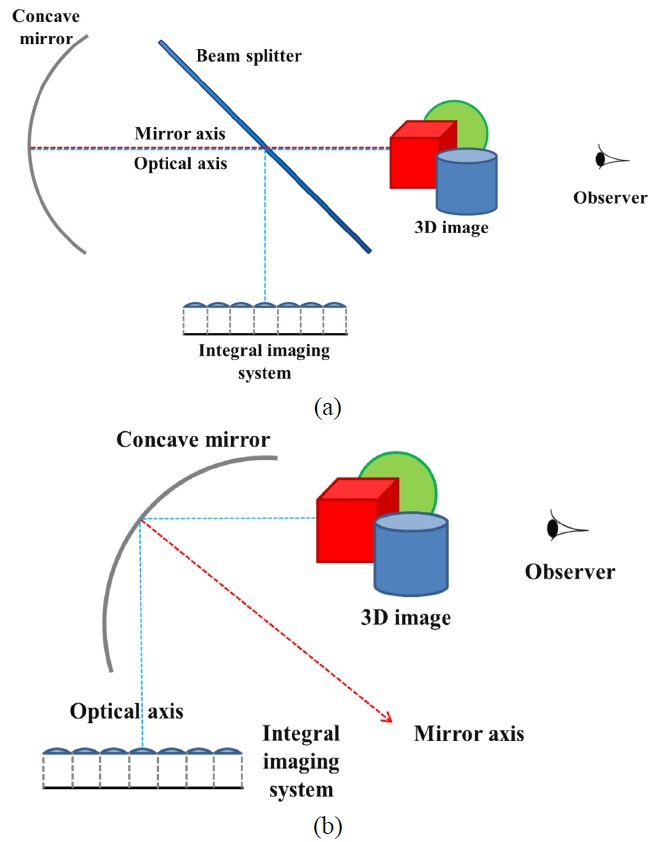
The Fresnel lens, which is composed of the tiny concentric circular prisms that refract the parallel rays to a focal point, is generally used as the floating device in the integral floating system because it induces less aberration compared with the general spherical lens. However, the Fresnel lens cannot be perfectly free of the aberrations [18-19] and because of its circular prism patterns , circular seam noise and optical loss are inevitable, causing the degradation of the image quality [5]. The concave mirror which is optically the same with the convex lens can be used as the floating device to reduce the disadvantages of the Fresnel lens and to improve the floating image quality. However, using the concave mirror as the floating device incurs the problem of the on-axis system configuration, which means the object and the observer are located on the same side of the mirror, because the mirror switches the direction of the optical axis. Therefore, the object space and the image space of the concave mirror are overlapped in the on-axis floating system as shown in Fig. 1 (a). In this case, it is impossible to compose the floating system without a beam splitter. Due to the characteristics of the beam splitter, the optical efficiency of the system should be decreased to less than
50%. Furthermore, the system using the beam splitter should be complicated and bulky [17].
The off-axis integral floating where the optical axis of system is tilted from that of the mirror can be a solution of the problems mentioned above as shown in Fig. 1 (b). The off-axis integral floating system can accomplish the relatively simple system configuration with high optical efficiency without the seam noises from the Fresnel lens patterns. But the off-axis integral floating causes the image deformation which isresulted from the optical aberrations. Therefore, the pre-distortion image is needed to reconstruct a correct 3D floated image. In this paper, we analyze and simulate the image deformation due to the tilted angle between the optical axis of the system and the mirror. Using the simulation data, we can make the pre-distortion image which can be floated as the correct image. For the off-axis integral floating system, the compensated elemental image is generated for the pre-distortion integrated image. The experimental results of the image deformation analysis and the off-axis integral floating are presented to prove the feasibility of the proposal.
II. ANALYSIS OF IMAGE DISTORTION
The monochromatic optical aberrations can be classified into the five cases; the spherical aberration, the stigmatism,
the coma, the field curvature, and the distortion. The former three cases are the focusing error, which means the rays cannot converge on the focal point or the image point because of the surface curvature and the tilting axis, and can influence the image definition. The other two cases are the error about the image position due to the tilting axis and the chief rays. These are about the image deformation and must be considered in the off-axis image process. We start with the simulation of the image deformation due to the tiling angle using the simple geometrical optics.
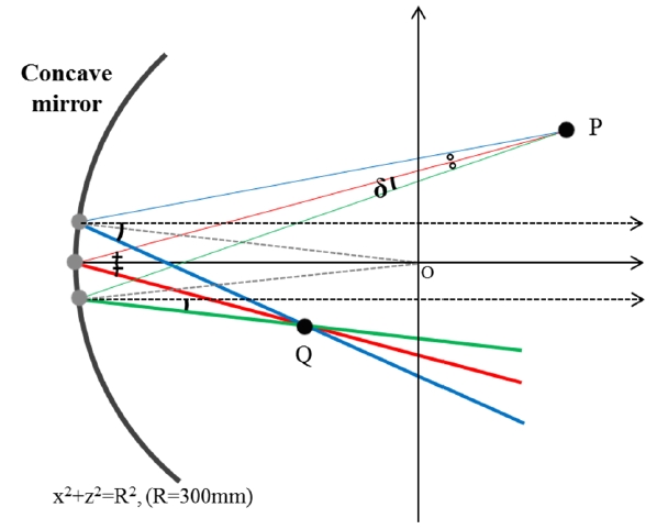
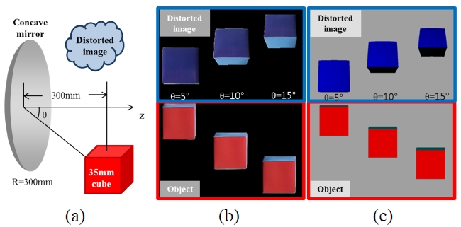
Figure 2 shows the simulation for the image distortion. Firstly, we select two rays which start to travel from one source point P of the object and have the sufficiently small variations of the angle from the center ray from the source point and travels toward the center point of the spherical concave mirror. And then we find the intersection point of the two reflection rays which is the image point Q. Applying this process to the other points of the object, we can get the whole reflection image of the object. Fig. 3 shows the comparison of the image of the real object and the simulation results. The pattern of simulation results is coincident with the real image distortion.
Based on the simulation of the image distortion, we can make the process to resolve the image distortion because the process of the image formation is reversible. In other words, we can find the pre-distortion image which forms the correct image through the concave mirror by performing the reverse process of the simulation for the image distortion, so that the pre-distortion image can compensate the image distortion.
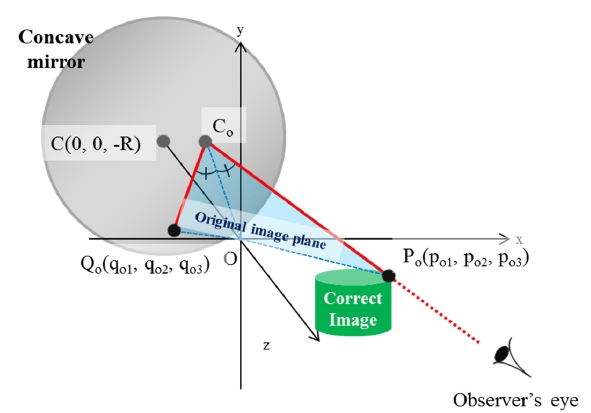
In this chapter, we deal with the pre-distortion process to resolve the image distortion, which means the sequential operations to generate the compensated image. In order to find the pre-distortion image, we assume that an observer’s eye sees the point Po which is one point of the correct 3D image as shown in Fig. 4. Then, we can find the pre-distortion point Qo which converges to the point Po after the reflection by the concave mirror. The point Qo can be calculated through finding the chief ray that expresses the viewing direction and applying the reverse method of the simulation for the image distortion.
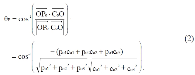
The chief ray is determined by the point Po and the position of the observer’s eye. The reflection point Co can be calculated by solving the equations of the chief ray and the concave mirror. To make the calculation simple, the points Po and Co should be projected onto the z-x plane. The distance from the point O to the point Po,

and the angle between

and the optical axis of the concave mirror, θP, are given as follows;

When the point Co is projected to the point C (0, 0, -R), where R is radius of the concave mirror. The x, y, and z coordinates of the point P, p1, p2, and p3, are given as;


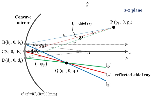
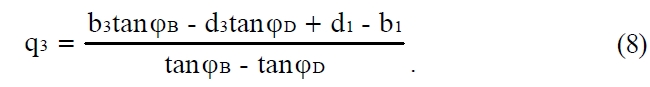
And then, we should calculate the pre-distortion point Q which is the concave mirror image of the point P. Fig. 5 shows the process for calculating the point Q. We select the two rays very near the chief ray, lB and lD, which start from the point P. When the reflection rays of lB and lD are defined as lB’ and lD’, the point Q can be obtained by solving the equations of lB’ and lD’. The point Q(q1, q2, q3) is given by


Because the point Q is the pre-distortion point just on the z-x plane, we should project the point Q onto the original image plane, and then the real pre-distortion point Qo can be derived. This projection process can be performed by the three linear equations derived by the location relationships among the points on the original image plane and z-x plane. Because the point Qo is on the original image plane, the first equation of the simultaneous equations is derived by finding the plane equation of the original image plane
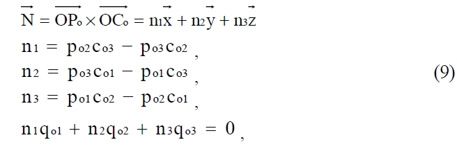
where the vector

is a normal vector of the original image plane. The other two equations can be derived by two scalar production;
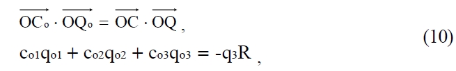
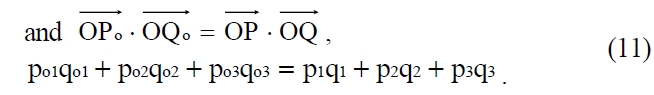
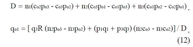
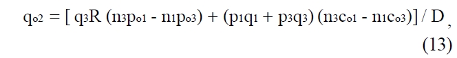
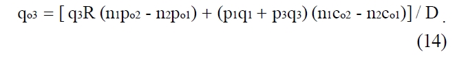
Finally, the pre-distortion point Qo can be obtained by solving the three equations, (9), (10), and (11) as follows;
As mentioned above, the whole pre-distortion image for the correct 3D image can be found by adopting this method to the other points of the correct 3D image. The pre-distortion image can be used to generate the compensated elemental image which can be reconstructed to the pre-distortion integrated image.
The obtained pre-distortion image is for only one view of the observer’s eye. If the viewing direction of observer is moved, the chief ray should be changed. Therefore, the pre-distortion image should be generated according to the viewing direction of the observer.
Using the pre-distortion process, we can reconstruct the correct 3D image without the image distortion using the off-axis integral floating system with the concave mirror. The sequential operations of the reconstruction process are as follows; (1) the 3D image to be displayed is assumed and defined as the certain coordinates. (2) The pre-distortion image coordinates are calculated by the pre-distortion process as described in chapter 3. (3) The compensated elemental image is generated using the pre-distortion image coordinates in consideration of the system specification of the integral imaging system to be used. (4) The pre-distortion integrated image is reconstructed by the defined integral imaging system. (4) Finally, the concave mirror is set up in front of the integral imaging system with the proper location and angle to project the correct 3D floating image.
Through the process, we can achieve the off-axis integral floating system using the concave mirror with the high efficiency and the simple structure and no distortion.
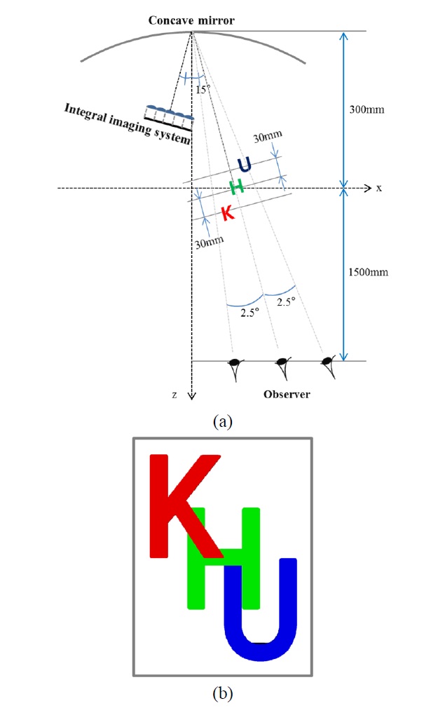
In order to prove the compensation effect of the proposed method, the 15° off-axis integral floating system is set up. The 3D image to be displayed is composed of three characters, ‘K’, ‘H’, and ‘U’ whose heights are 35 mm. As shown in Fig. 6 (a), the character ‘H’ is located on 300 mm along the z-axis and 15° tilted from the axis. The character ‘K’
and ‘U’ are located on 30 mm nearer and farther than the character ‘H’ along the optical axis, respectively. Fig. 6 (b) shows the front scene of the computer-generated three characters used as a 3D object.
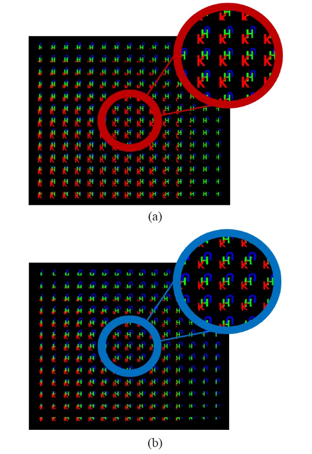
Table 1 describes the specifications of the experimental setup such as the lens array, the display device, and the concave mirror. The pickup process of the compensated elemental image is performed by the computational simulation tools. Fig. 7 (a) shows the elemental images of the non-compensated image while Fig. 7 (b) shows the compensated
[TABLE 1.] Specifications of experimental setup
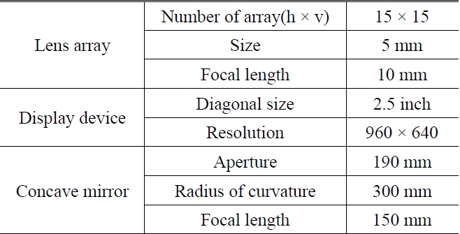
Specifications of experimental setup
elemental imaging for the pre-distortion integrated image when both angles of the off-axis and the view are the same as 15°.
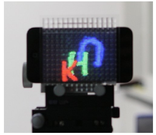
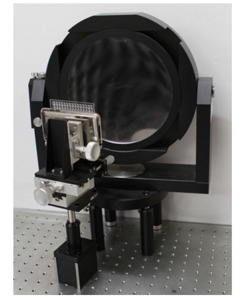
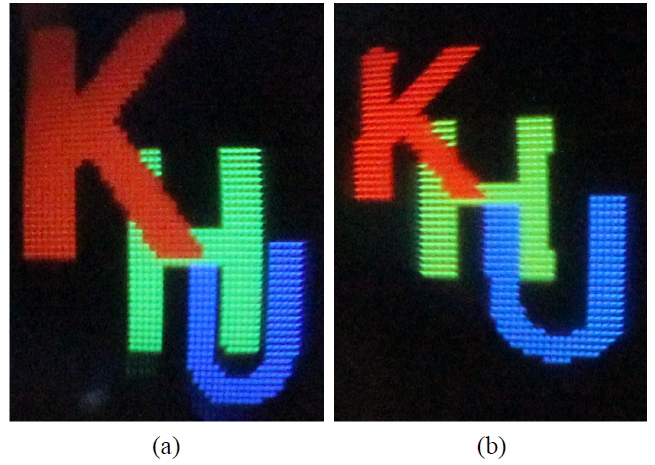
Figure 8 shows the implemented off-axis integral floating system. And Fig. 9 shows the pre-distortion image reconstructed by the integral imaging system which is part of the off-axis integral floating system. Fig. 10 and 11 represent the experimental results. The images of experimental results can be taken by camera located on the positions of the observer’s eyes indicated in Fig. 6 (a). As shown in Fig. 11, the non-compensated 3D image and the compensated 3D image are compared with each other when the angles of the off-axis and of the view are the same as 15°. The character ‘K’ becomes larger than the other characters due to the lens effect of the concave mirror. Reversely, the character ‘U’ becomes smaller due to the same reason for
the character ‘K’. The characters in the non-compensated 3D image are wider as the characters get farther from the z-axis. The characters in the compensated 3D image have mostly uniform sizes compared with the non-compensated 3D image.
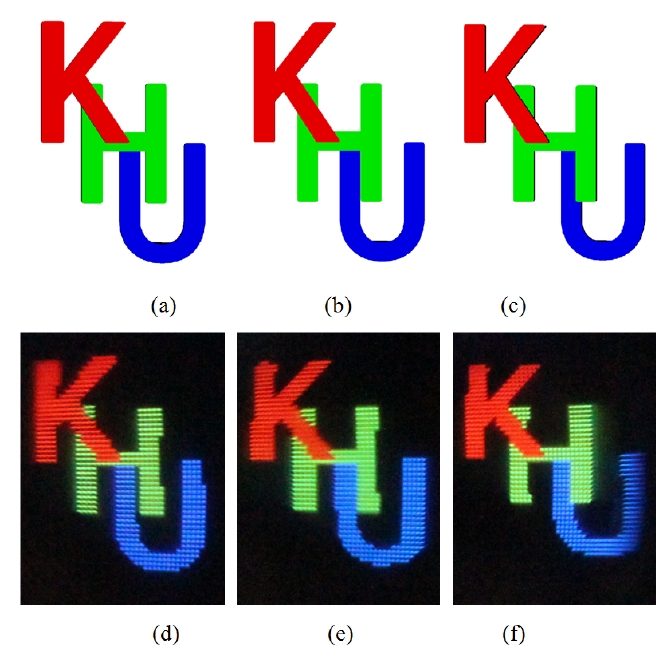
Figure 11 shows the results of the compensated 3D images in three different views, 12.5°, 15°, and 17.5°. Fig. 11 (a), (b), and (c) are the simulation results and Fig. 11 (d), (e), and (f) are the experimental results in each view. The simulation results and the experimental results are coincident with each other.
The image distortion of the off-axis integral floating system using the concave mirror is analyzed to resolve. In the integral floating system using the concave mirror, the off-axis structure is inevitable, which results in the image distortion. So, we analyze the image distortion and generate the pre-distortion image which compensates the image deformation caused by the tilted angle through the pre-distortion process. And then, we can realize the distortion-free off-axis integral floating system with the high efficiency and the simple structure. The experimental results for one-view are presented in only one each elemental image. However, the free-viewing direction system can be realized by using the head-tracking method or the directionally selective pick-up method for the integral imaging system.