검색 전체 메뉴
PDF
맨 위로
OA 학술지
Highly Angle-tolerant Spectral Filter Based on an Etalon Resonator Incorporating a High Index Cavity
  • 비영리 CC BY-NC
  • 비영리 CC BY-NC
ABSTRACT
Highly Angle-tolerant Spectral Filter Based on an Etalon Resonator Incorporating a High Index Cavity
KEYWORD
Spectral filters , Etalon , Thin films , Resonators , Metal layers
  • I. INTRODUCTION

    Recently, free space optics technology has been extensively applied to various fields, such as visible light communications, military training systems like multiple integrated lasers engagement systems, and last-mile wireless interconnects. A spectral bandpass filter featuring a wide field-of-view is regarded as one of the essential elements for the implementation of those applications [1, 2], taking into account the fact that it may play the role of mitigating undesirable surrounding noise caused by sunlight or lighting equipment, so as to prevent the malfunction of receivers [3]. So far, spectral filters based on multi-layered films have been actively attempted, because of their simple structure and low cost [4, 5]. However, their performance in terms of center wavelength and transmission efficiency has been critically dependent on the angle of the light beam [6-10], which is widely regarded as a paramount issue with a spectral filter used for receivers, which are applied to free space optics and image sensors. A device tapping into a complicated photonic crystal structure was also suggested, to alleviate the angular dependence [11-13]. Although the variation in wavelength remained relatively small, transmission degraded excessively with increasing angle. Moreover, the operation was severely polarization sensitive. In this paper, we have proposed and built a near-infrared bandpass filter incorporating an etalon resonator, enabling an extended angular tolerance and small polarization dependence. The resonator was created in such a way that a high index dielectric cavity made of TiO2 film is sandwiched by a pair of metallic mirrors in Ag/Ge. It was confirmed theoretically and experimentally that the influence of angle upon the resonant wavelength and transmission efficiency was remarkably diminished, as compared to the device using a low index cavity, such as SiO2.

    II. PROPOSED ANGLE TOLERANT FILTER AND ITS DESIGN

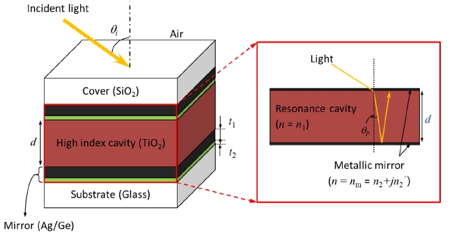
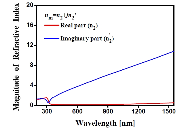
    We aimed to develop an angle tolerant spectral bandpass filter operating at ~900 nm wavelength. As illustrated in Fig. 1, the proposed etalon resonator, realized in a glass substrate, is composed of a high index TiO2 cavity embedded in two identical thin Ag/Ge mirrors. An oxide film is formed on top of the etalon as a protective layer, thereby avoiding the oxidation of the exposed Ag layer. It is noted that a thin Ge film has been combined with the Ag layer for the purpose of not merely reducing the optical loss caused by its surface roughness but also helping strengthen its adhesion to the oxide and TiO2 layers. An incident beam impinging upon the etalon structure is supposed to undergo a strong resonance that results in periodic transmission peaks [14].

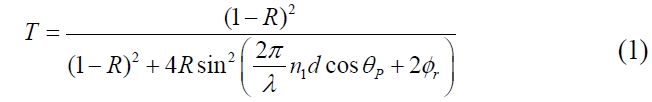
    The optical spectral response is given by the following Equation 1 [15]. Here, R is the reflectance of the mirror, d and n1 are the thickness and refractive index of the cavity, and λ is the wavelength. r is the reflection phase shift from the thin Ag film in conjunction with the substrate or cover, which is both angle and polarization dependent. Although the phase shift may be precisely discovered by considering the dispersion characteristics of the metal, it was approximated to be r = π, which is as in the case of a perfect metal, for studying the influence of the cavity index on the angle dependent performance of the proposed filter [15]. The propagation angle θP inside the cavity, which is determined by the n1 and the angle of incidence θi, is directly related to the resonant wavelength. In order to enlarge the effective angle, the sensitivity of filter performance to θi should certainly be suppressed by decreasing θP. The dependence of the fractional change in a resonant center wavelength λc upon the incidence angle is derived such that it can be expressed as the following Equation 2, indicating that for a constant angle the relative wavelength shift is decreased by raising the refractive index of the cavity medium [16]. It should be, however, noted that the influence of the reflection phase term r has been ignored while deriving the Equation 2, which is approximately valid for relatively small angles of incidence. This will be

    evident with reference to the simulation results as discussed later. In order to overcome its limitations, therefore, we have resorted to numerical simulations.

    image
    image

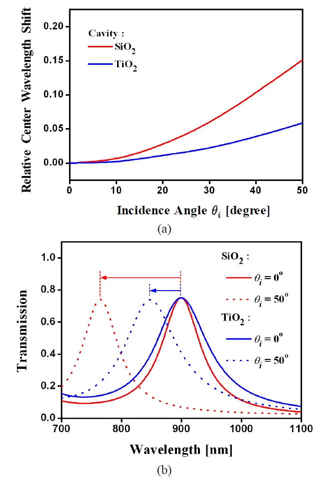
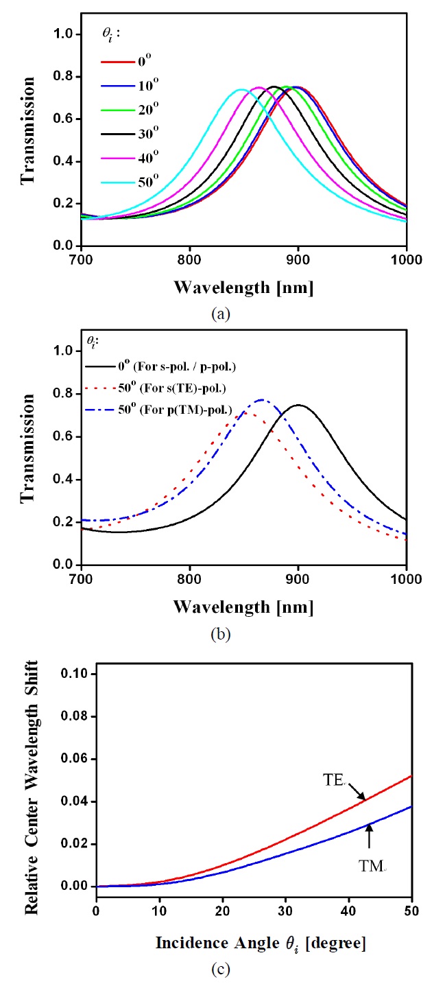
    We theoretically investigated the spectral response of the proposed filter for two different cavity materials of TiO2 (n = ~2.3) and SiO2 (n = ~1.45). As for the structural parameters, the thicknesses of the TiO2 cavity and the Ag mirror film were chosen to be d = 313 nm and t1 = 14 nm, respectively. As mentioned above, an ultrathin Ge layer of 2 nm thickness was introduced to improve the surface roughness of the Ag layer and to strengthen its adhesion to the oxide and TiO2 layers; and a 170 nm thick oxide film served as a protective layer. In order to accurately estimate the actual transfer characteristics of the proposed device, the finite thickness of the metallic mirrors and their dispersion were taken into account with the assistance of a commercially available simulation tool, GSolver, based on a rigorous coupled-wave analysis. Fig. 2 shows the dispersion characteristics of the Ag used for the mirror, which has been derived from the Drude model. For an angle θi, ranging from 0 to 50°, the shift in resonant wavelength Δλc was first examined with respect to the case of normal incidence of θi = 0°. As shown in Fig. 3(a), the relative wavelength shift, which is defined as Δλcc, was found to be much smaller for the high index cavity in TiO2, compared to the low index cavity in SiO2. In particular, Fig. 3(b) compares the responses corresponding to θi = 0 and 50° for TiO2 and SiO2 cavities. For filters with the same configuration, the high index cavity provided much smaller variation in the center wavelength than the low index cavity, as predicted.

    Next, Fig. 4(a) shows the calculated optical response for unpolarized light when θi varies from 0 up to 50°, in 10° steps. For normal incidence, the resonance was centered at ~900 nm wavelength with a transmission of ~75%. Overall, the relative center wavelength shift and fluctuation in maximum transmission were observed to be approximately 0.06 and 2%, respectively. We have explored the influence of the polarization upon the performance of the proposed filter with the incidence angle. Fig. 4(b) and (c) show the spectral transmission for angles of θi = 0° and 50° for the s(TE)-polarization and p(TM)-polarization. The device exhibited no polarization dependence for the normal incidence as predicted. However, as observed in Fig. 4(b), a slight discrepancy between the two polarizations was actually witnessed for the extreme angle of θi = 50°. The difference in the relative center wavelength shift between the TE and TM polarizations was found to increase slightly with the angle. Next, in order to identify the limit in the peak transmission at the center wavelength, we observed the transmission as well as the reflection for the filter as shown in

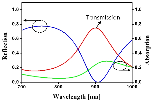
    Fig. 5. Since the reflection is negligibly small, the limit in the peak transmission, which is equivalent to the optical loss, is believed to be mostly attributed to the absorption induced by the Ag mirror.

    III. DEVICE FABRICATION AND EXPERIMENTAL RESULTS

    The proposed filter device was manufactured following the procedure described here: Three layers, comprising a

    film of Ag (t1 = 14 nm)/Ge (t2 = 2 nm) for the bottom mirror, a TiO2 (d = 313 nm) film for the etalon cavity, and a similar top mirror, were successively deposited on a glass substrate, via argon sputtering. A 170 nm thick oxide film was then produced on top of the mirror, to complete the device. For the purpose of verifying the effect of the Ge layer on the surface quality of the Ag layer, atomic force microscopy images of Ag films with and without the deposited Ge film were taken, as shown in Fig. 6. The RMS roughness as measured decreased considerably from 8.4 to 0.54 nm, thereby relieving the optical scattering loss stemming from the uneven surface of the film [17].

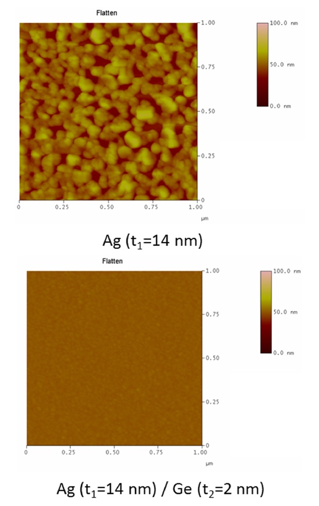
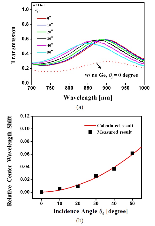
    A collimated light beam, generated by a halogen lamp, Model LS-1, Ocean Optics, was used to illuminate the prepared filter, which was mounted on a precision rotational stage, while the output was captured by use of a spectrophotometer, Model USB-4000-VIS-NIR, Ocean Optics. Fig. 7(a) shows the transfer characteristics for an incidence angle spanning 50°. In the case of normal incidence, the center wavelength was ~900 nm as anticipated. The demonstrated peak transmission was nearly 60%, which was elevated by the amount of 30% as compared to the case involving no Ge film. This is due to the enhanced surface roughness of

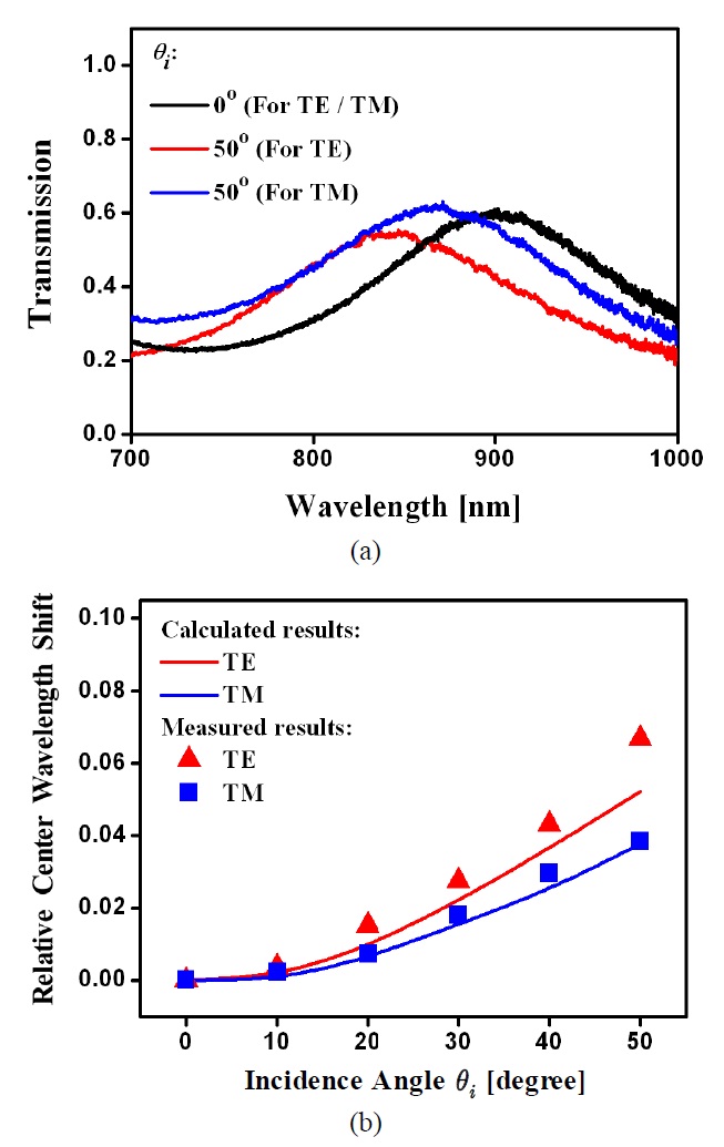
    the Ag/Ge film, leading to lower optical loss. The achieved transmission was still lower than the theoretical level by the amount of ~15%, which may be attributed to the unwanted absorption incurred by the fabricated Ag mirror [17]. The center wavelength slightly shifted from 900 nm to ~845 nm, as the angle increased from 0 up to 50°. As plotted in Fig. 7(b), the relative wavelength alteration obtained was accordingly observed to be as small as ~0.06, which is in good correlation with the theoretical result. The change in peak transmission was 4% or so while the spectral bandwidth was almost maintained. Finally, the measured transmissions for incidence angles of θi = 0° and 50° are shown in Fig. 8(a) for the TE and TM polarizations, while Fig. 8(b) reveals the corresponding relative wavelength shift as a function of the angle for the two polarizations. As anticipated from the simulation results included in Fig. 4(b) and (c), the polarization dependence was observed to slightly increase with the incidence angle.

    IV. CONCLUSION

    In summary, a high angular tolerance infrared wavelength filter was constructed relying on a simple etalon resonator, utilizing a high index TiO2 cavity integrated into a pair of Ag/Ge films. Its angular sensitivity was theoretically and experimentally proven to be sufficiently low in terms of the relative wavelength shift and the variation in transmission efficiency. We anticipate our device will be readily adopted to warrant the viable operation of free space optics based modules/systems regardless of a variety of surrounding noise sources.

참고문헌
  • 1. Fohl T. (1994) “Wide angle, narrow band optical filter” google
  • 2. Johnson B. E., Lindsay T. A., Brodeur D. L., Morton R. E., Regnier M. A. (1994) “Wide-angle, high-speed, free-space optical communication system” google
  • 3. Moreira A. J. C., Valadas R. T., Duarte A. M. 1996 “Reducing the effects of artificial light interference in wireless infrared transmission systems” [in Proc. IEEE Colloquium on Optical Free Space Communication Links] P.5/1-510 google
  • 4. Minas G., Ribeiro J. C., Martins J. S., Wolffenbuttel R. F., Correia J. H. (2004) “An array of Fabry-Perot optical-channels for biological fluids analysis” [Sens. Actuators A] Vol.115 P.362-367 google
  • 5. Bartek M., Correia J. H., Wolffenbuttel R. F. 1998 “Micromachined Fabry-Perot optical filters” [in Proc. 2nd Int’l Conf. on Adv. Semiconductor Devices and Microsystems] P.283-286 google
  • 6. Yoon Y., Shim J., Jang D., Kim J., Eo Y., Rhee F. (2002) “Transmission spectra of Fabry-Perot etalon filter for diverged input beams” [IEEE Photon. Technol. Lett.] Vol.14 P.1315-1317 google
  • 7. Jablonski M., Tanaka Y., Yaguchi H., Furuki K., Sato K., Higashi N., Kikuchi K. (2001) “Entirely thin-film allpass coupled-cavity filters in a parallel configuration for adjustable dispersion-slope compensation” [IEEE Photon. Technol. Lett.] Vol.13 P.1188-1190 google
  • 8. Wang Q. H., Li D. H., Peng B. J., Tao Y. H., Zhao W. X. (2008) “Multilayer dielectric color filters for optically written display using up-conversion of near infrared light” [IEEE J. Display Technol.] Vol.4 P.250-253 google
  • 9. Baker M. L., Yen V. L. (1967) “Effects of the variation of angle of incidence and temperature on infrared filter characteristics” [Appl. Opt.] Vol.6 P.1343-1351 google
  • 10. Yoon Y. T., Lee S. S. (2010) “Transmission type color filter incorporating a silver film based etalon” [Opt. Express] Vol.18 P.5344-5349 google
  • 11. Nakagawa W., Sun P., Chen C., Fainman Y. (2002) “Wide-field-of-view narrow-band spectral filters based on photonic crystal nanocavities” [Opt. Lett.] Vol.27 P.191-193 google
  • 12. Cheong B. H., Prudnikov O. N., Cho E., Kim H. S., Yu J. (2009) “High angular tolerant color filter using subwavelength grating” [Appl. Phys. Lett.] Vol.94 P.21304 google
  • 13. Koyama S., Inaba Y., Kasano M., Murata T. (2008) “A day and night vision MOS imager with robust photonic-crystal-based RGB-and-IR” [IEEE Trans. Elect. Dev.] Vol.55 P.754-759 google
  • 14. Booth R. A., Reinhard D. K. 2001 “Diamond thin film Fabry-Perot optical resonators” [in Proc. The 6th Applied Diamond Conf./Second Frontier Carbon Technology Joint Conf.] google
  • 15. Born M., Wolf E. 1999 Principles of Optics google
  • 16. Saleh B. E. A., Teich M. C. 2007 Fundamentals of Photonics google
  • 17. Chen W., Thoreson M. D., Ishii S., Kildishev A. V., Shalaev V. M. (2010) “Ultra-thin ultra-smooth and low-loss silver films on a germanium wetting layer” [Opt. Express] Vol.18 P.5124-5134 google
이미지 / 테이블
  • [ FIG. 1. ]  Configuration of the proposed spectral filter featuring high angular tolerance.
    Configuration of the proposed spectral filter featuring high angular tolerance.
  • [ FIG. 2. ]  Dispersion characteristics of Ag metal.
    Dispersion characteristics of Ag metal.
  • [ FIG. 3. ]  Transfer characteristics of an etalon filter depending on the cavity materials of SiO2 and TiO2 for unpolarized light: (a) Relative center wavelength shift with incidence angle θi (b) Spectral response for θi = 0° and 50°.
    Transfer characteristics of an etalon filter depending on the cavity materials of SiO2 and TiO2 for unpolarized light: (a) Relative center wavelength shift with incidence angle θi (b) Spectral response for θi = 0° and 50°.
  • [ FIG. 4. ]  (a) Calculated spectral response in terms of various incidence angles for unpolarized light (b) Calculated spectral response with the polarization for incidence angles of 0° and 50° (c) Theoretical relative center wavelength shift with respect to the angle for TE and TM polarizations.
    (a) Calculated spectral response in terms of various incidence angles for unpolarized light (b) Calculated spectral response with the polarization for incidence angles of 0° and 50° (c) Theoretical relative center wavelength shift with respect to the angle for TE and TM polarizations.
  • [ FIG. 5. ]  Calculated optical transmission and reflection for the proposed etalon filer.
    Calculated optical transmission and reflection for the proposed etalon filer.
  • [ FIG. 6. ]  Atomic force microscope (AFM) images of Ag films with and without a Ge film.
    Atomic force microscope (AFM) images of Ag films with and without a Ge film.
  • [ FIG. 7. ]  Achieved filter performance with respect to the angle of incidence for unpolarized light: (a) Spectral response (b) Relative center wavelength shift.
    Achieved filter performance with respect to the angle of incidence for unpolarized light: (a) Spectral response (b) Relative center wavelength shift.
  • [ FIG. 8. ]  (a) Measured spectral transmission with the polarization with respect to incidence angles of 0° and 50° (b) Demonstrated relative center wavelength shift in terms of the angle for TE and TM polarizations.
    (a) Measured spectral transmission with the polarization with respect to incidence angles of 0° and 50° (b) Demonstrated relative center wavelength shift in terms of the angle for TE and TM polarizations.
(우)06579 서울시 서초구 반포대로 201(반포동)
Tel. 02-537-6389 | Fax. 02-590-0571 | 문의 : oak2014@korea.kr
Copyright(c) National Library of Korea. All rights reserved.