The common fluorescent lamps used today operate with environmentally hazardous substances under high-energy consumption, whereas the light-emitting diode (LED) is more eco-friendly, 90% energy efficient, and longer lasting, which have drawn much attention in the “green-energy” industry. The LED industry has expanded from lighting to LED-TV and -notebook, and even to cell phones [1-5].
The technology that wireless communication is available wherever there is LED lighting, has recently been developed.In particular, wireless visible light communication (VLC) has drawn much attention these days, especially the LED-based VLC. VLC refers to a communication that uses visible light range which can be seen to the human's eyes, and also a new information and communication technology that using infrastructure in which lightings visible to the human's eyes such
as incandescent and fluorescent lightings are replaced by light emitting diode (LED), information is sent to each object and the information sent is reused. In other words, it can be said that VLC is a technology which transmits and exchanges information using lights including visible light range (VI S: 380~780 nm), or ear-infrared ray (NIR: 700~2,500 nm)range emi tting from home lighting, outdoor advertising signs, traffic signals, display of various devices, etc, and a new optical wireless technology differentiated from optical communications through the existing optical fiber [6-9].
The automatic voltage regulator (AVR) family, including ATmega16, boasts of very fast command processing speed, which independently uses buses to access program memory and inner data memory. In addition, AVR is applied with in system programming, which embeds flash memory for program code in chips, into which a program can be downloaded by the user. The ATmega16 device is cheap and Atmel offers a free AVR studio (IDE software) and macro-assembler and can use the GCCseries WinAVR free (does ‘free’ imply ‘no money’ here) as a Ccompiler [10].
In this study, we analyzed for modulation characteristics in the LED integrated interface using the switching driving module. (integrated interface using the switching driving module) Then, we implemented the integrated LED interface with a system’s transmitter/receiver to evaluate the applicability of the next generation home network.
As LED based lighting technology develops and expands in its distribution, visible light wireless communication technology based on LED lightning will become an area of much interest in the home network industry. In particular, the LED applications were networked with a visible light wireless communication system.
The VLC lighting control system utilizing infrared communication used an infrared remote controller as a medium for communication The VLC lighting control system utilizing infrared communication used an infrared remote controller as a medium for communication. The VLC transmitter part and VLC receiver part were mounted with an infrared sensor. The system in this study transmits data in the infrared remote controller to the VLC transmitter part mounted with an infrared sensor . The data are converted into a transistor-transistor logic (TTL) signal by the
ILX232N chip and sent through micro-controller to LED emitting part. Through the VLC emitting part, the LED, data are sent to the visible light reception sensor in the VLC reception part and OP-amp circuit amplifies the weak electrical data signal which is transmitted to the PC via the RS-232C cable through the micro-controller and ILX232N chip.
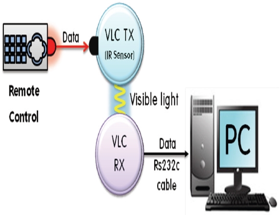
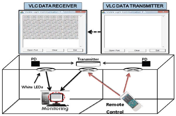
The system in this study uses the infrared remote controller as a medium for communication, and the information transmission system is shown in Fig. 1.
Besides, we made visible light communication data transmission/reception program using the computer programming language, Visual C++ and input letters in it so that we could monitor to see if we were able to communicate exactly before we evaluated its performance and they we could see the data processing process in real time. What is important at this point is to make an exact connection of transmission/reception port drivers in both computers.
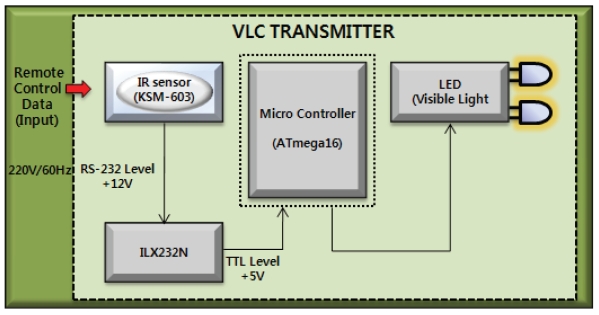
The block diagram of the VLC transmission part is shown in Fig. 2. It consists of infrared sensor KSM60WLM, MCU ATmega16 chip, high intensity LED module (6 pcs), and ILX232N chip, which is used for TTL signal level conversion.
The infrared remote controller sends a data signal through IR sensor KSM60WLM and the signal is converted by the ILX232N chip to the TTL signal level and sent through the micro-controller to the LED emitting part.
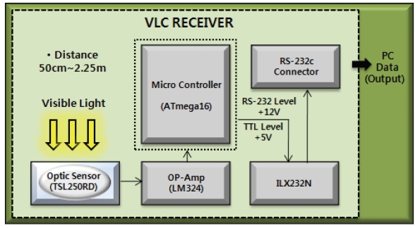
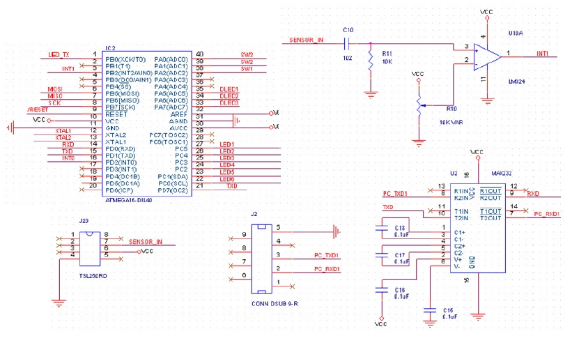
The VLC reception part consists, as shown in Fig. 3, of
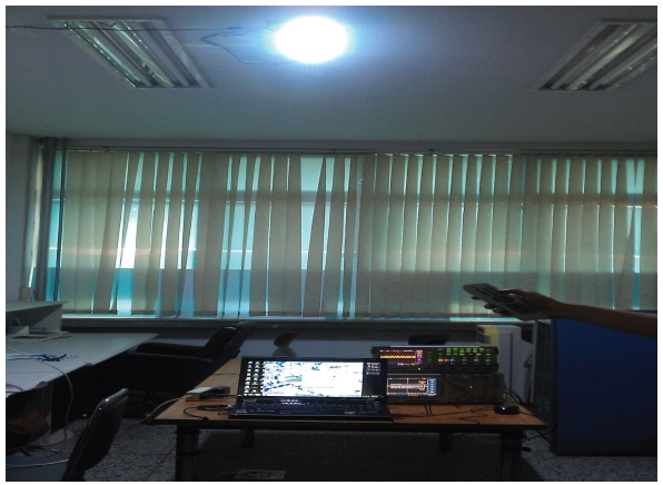
[Fig. 6.] Visible light wireless communication system performance evaluation and connection feature.

TSL250RD and MCU ATmega16 chip, which are visible light reception sensors used to receive data signal sent from LED. The data signal received through the visible light reception sensor is sent through MCU and OPAMP LM324N chip to the PC.
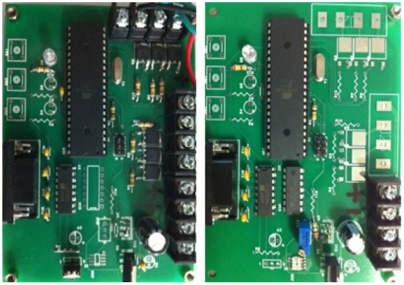
2.4 Manufactured transmission and reception
As shown in the Fig. 4(a), white LED in the transmission part uses 6 modules consisting of Good i-Tech's 21 high intensity white LEDs. As the IR remote controller drives the white LED, the light signal transmitted through free space is sent to the visible light sensor in the transmission part located at the opposite side of VLC reception. Figure 4(b) indicates the VLC reception part,which uses TAOS's visible light reception sensor - TSL250RD chip. The data signal transmitted from the VLC transmission part enters the visible light reception sensor and the data signal is converted to a weak electrical signal, which is amplified by the op-amp -LM324N chip to a TTL level signal.
Figure 5 shows the integrated interface board for infrared communication based on the VLC system. The VLC transmission part and reception part were designed with a switching driving module. In Fig. 5, the left shows the VLC transmission part with a mounted IR sensor, LED module, the right shows the reception part that receives the data transmitted from the LED. This study was carried out to solve problems such as radio frequency (RF) band depletion, confusion risk, and security loss of the existing VLC system. A schematic of the setup for analyzing the modulation effect is shown in Fig. 1.
The experimental configuration shown in Fig. 6 was adopted to evaluate the performance of the lighting dimming-based VLC system. Time varying scope and a power intensity system were used to measure the voltage detected at the visible light reception sensor during the day and at night indoors. The modulation effectiveness of the integrated interface with a controlling switching light module was also evaluated.
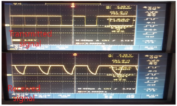
Figure 7 shows the oscilloscope pulse waveform of the visible light measured at the receiver part and transmitter part according to the transmission of the text file. As the distance between
reception and transmission increases, the signal level at the reception part reduces. In this experiment, communication at a distance of 2.25 m or more was weak or nonexistent, so the maximum communication distance was 2 m or so. In this experiment, for stable data transmission, the distance between the two transceivers was 50 cm, data was 8 bit, and in the state of non-parity bit and flow control, the transmission speed was 9,600 bps. At a distance of 2.25 m or more, it was difficult to receive data accurately due to weak intensity of light, but the data transmission process had no problems.
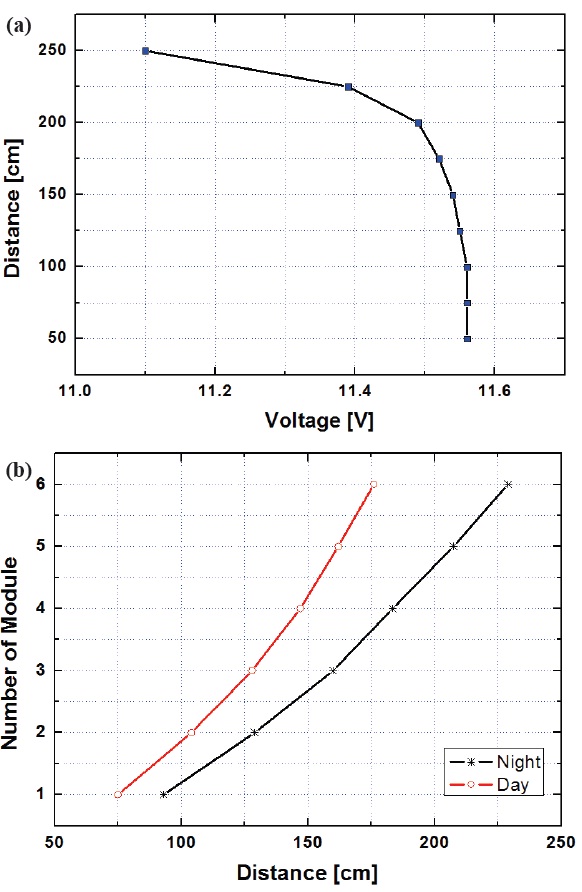
Figure 8 is the result of calculation of the voltage detected at the visible light sensor at the highest LED brightness. It was almost same at 50 cm ~ 2 m, but the voltage reduced sharply at more than 2.25 m, 11.56 V at 50 cm, and 11.1 V at 2.5 m, which was a voltage loss of 0.46 V. At more than 2.25 m distance, it was difficult to receive data exactly due to the weak light intensity.
Figure 9 shows indicates the resulting values after measurement of distance between day and night depending on the number of LED modules. The communication distance was much better at night than during the day, for the data loss by natural light was much less. The error of the distance between day and night depending on the number of modules is about 20~50 cm. To improve the communication distance, the distance between LEDs should be narrowed; to improve light output emitted per unit area , the number of LED modules should be increased. The intensity of the radiation actually emitted from indoor lighting is much more than this (what does ‘this’ refer to My paper in the current VLC system module), so the transmittable distance would be increased.
Figure 10 shows a capture of monitoring screen that observes
the status of transmission using the program manufactured with computer programming language. Visual C++ was manufactured with a computer programming language that ordinary users may use easily and we could see if transmission and reception between lighting and computer operates smoothly by inputting the letter. You first open the reception port program connected to the computer and then press the data information number key to send data. After we input '1, 2, 3, 4, 5' numbers consecutively, we checked if it properly received the numbers from the reception part. As it consists of basic number source values, you can replace the source numbers at any time, if desired. We can also control light dimming with a remote controller to communicate at a desired light intensity.
As a result, when we used all 6 LED modules, the best performance and transmission with no errors were achieved up to 2 m. To improve communication performance, the number of LEDs should be increased to improve light output per unit area. Currently, 6 LED modules consisting of 21 LEDs were used, but more modules could be used to increase the intensity of the radiation actually emitted in indoor lighting to increase the data transmission distance.
We implemented an LED lighting dimming-based visible light wireless communication system and analyzed reception property using oscilloscope and the program made by using a computer programming language. From the initial value of distance to few ~2.5 m approximately, the voltage loss was 0.46 V due to external light interference. External light interference occurred and light intensity was lost by external impact and thus data had to be modified or reset repeatedly.
When we used 6 modules through the remote controller's lighting dimming, data could be transmitted up to 1.76 m without any errors during the day and up to 2.29 m at night with around 2~3% communication error. The distance error included problems such as RF band depletion, confusion risk, and security loss in the existing VLC system.