In order to develop electrical insulation materials, epoxy/micro-silica composite (EMC) and epoxy/micro-silica/nanosilicate composite (EMNC) were prepared, and their tensile and flexural strength, AC insulation breakdown strength and thermal conductivity and thermal expansion coefficient were compared. Nano-silicate was prepared in an epoxy matrix by our AC electric field process. All properties of the neat epoxy were improved by the addition of micro-silica, which was improved much further by the addition of nano-silicate to the EMC system.
Various kinds of inorganic fillers such as silica (SiO2) [1], alumina (Al2O3) [2], mica [3], aluminum nitride (AlN) [4], titanium dioxide (TiO2) [5], etc. have been widely used for conventional polymer composites in order to apply them to insulation materials. In particular, epoxy composite systems with micro-sized silica particles are the most well-known for high voltage (HV) applications such as mold-type transformers, current transformers (CT), potential transformers (PT), metering out-fit (MOF) and gas switching gears [6,7], as well as low and medium voltage (LV and MV) applications such as pin and post type insulators, bushings, instrument transformers for current and voltage measurement, bus support assemblies,and switching and protection equipments [8,9]. Usually, the composites are used by loading micro-silica with ordinary particle size above 1μm and up to 100 μm., 65~80 wt% of micro-silica can be loaded in an epoxy matrix to achieve the same low level thermal expansion as copper or aluminum parts, which prevents exfoliating between the epoxy casting part and the metallic parts. Many electric apparatus are generally operated at 40~60℃ and are exposed to various heat-cycles from outside environmental temperatures [10]. In addition, the micro-silica can also enhance the electrical and thermal properties, hydrothermal aging and UV resistance of an epoxy matrix during the manufacturing process or their service lives.
recently, many researchers have been interested in the application of nano-sized fillers in an epoxy matrix [11-13]. Our previous work [11] showed that epoxy nanocomposites were remarkably improved by the addition of intercalated silicates. T. Tanaka and co-workers [12] showed that epoxy/layered silicate nanocomposite had much better insulation breakdown time than epoxy resin without fillers in needle-plate electrode geometry. Zou et al [13] reported the influence of humidity on the dielectric properties of epoxy nanocomposites filled with silica. Furthermore, a new concept involving the mixture of micro- and nano-fillers for epoxy-based composites has been considered by many researchers [14,15]. They reported that nano-silica or multilayered silicate improved the electrical and mechanical properties of epoxy resin/ silica microcomposites.
In this study, we prepared an epoxy/micro-silica composite (EMC), into which nano-silicate was mixed to prepare epoxy/micro-silica/nano-silicate composites (EMNC) for use as insulation materials of heavy electric equipments. The mechanical, electrical and thermal properties of these composites were compared.
A commercial DGEBA (diglycidyl ether of bisphenol A) type epoxy resin, YD 128 (Kukdo Chem. Co.) was used. The equivalent weight was 184~190 eew and the viscosity was 11,500~13,500 cps at 25℃. The curing agent was Me-THPA (3- or 4-methyl-1,2,3,6- tetrahydrophthalic anhydride) whose grade name was HN- 2200 (Hitachi Chem. Co.). It is widely used in the field of electric insulation. The accelerator was BDMA (benzyl-dimethyl amine, Kukdo Chem. Co.). CA0020 grade micro-silica with an average particle size of 3 μm was purchased from Sibelco Asia and was dried at 110℃ for 24 h in a vacuum oven and stored in desiccator before use. Cloisite® 10A (Southern Clay Products, Inc., USA) was used as a multilayered silicate, which was a natural montmorillonite modified with 2MBHT (dimethyl-benzyl-hydrogenated tallow quaternary ammonium) as a sort of quaternary ammonium salt. It was also dried at 110℃ for 24 h in a vacuum oven and stored in a desiccator before use.
2.2 Preparation of EMC and EMNC
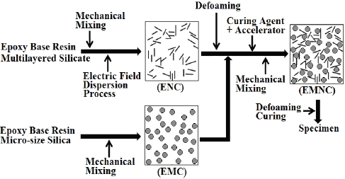
Figure 1 shows the preparation process for EMC and EMNC. To prepare EMC, DGEBA (100 g) and micro-silica (65 g) were well-mixed with a high-speed agitator at 5,000 rpm for 30 min, and then THPA (80 g) and BDMA (0.9 g) were added and mixed for 5 min. The matrix micro-silica weight ratio of the epoxy was 1.0:0.36. The mixture was poured into a mold and degassed in a vacuum oven and cured at 120℃ for 2 h,followed by continual postcuring at 150℃ for 2 h.
In order to prepare EMNC, epoxy base resin (DGEBA, 50 g) and Cloisite 10 A (1.0 g) were well-mixed in a bottle with a mechanical agitator for 30 min and then treated by an AC electric field process, which was developed by us [16]. The AC electric field was generated by a high voltage (HV) generator with the following conditions; (1) inter-electrode distance: 50 mm, (2) application voltage: 11 kV, (3) frequency: 1 kHz, and (4) application time: 60 min. Then the mixture was degassed in a vacuum oven for 30 min. DGEBA (50 g) and micro-silica (65 g) were well-mixed in another bottle with a high-speed agitator at 5,000 rpm for 30 min, and the mixture in the first bottle was added to the bottle and mixed at 5,000 rpm for 30 min. Then, THPA (80 g) and BDMA (0.9 g) were mixed for 5 min and cured in the same conditions as the EMNC preparation. The matrix: micro-silica nano-silicate weight ratio of the epoxy was 1.0:0.36:0.0053.
Dynamic mechanical analysis (DMA2980, TA Instrument Ltd.) was carried out in shear mode at the frequency of 1.0 Hz and heating rate of 10 °C/min. The sample dimension was 12.5×7.0×3.0 mm and the air purge rate was 110 ml/min.
Tensile and flexural tests were carried out by a universal testing machine (SHM-C-500, Shamhan Tech, Korea). Specimens for tensile tests were prepared under the recommendation of JIS B7502 and they were tested at a crosshead speed of 10 mm/min at 23℃ and 50% relative humidity. Specimens for flexural tests were prepared by three point bending method with the recommendation of JIS B7507 at a size of 70×10×4 mm. The span length was 50 mm and crosshead speed was 10 mm/min at the same temperature and humidity in the tensile test.
An AC insulation breakdown test was carried out in anarrangement of sphere to sphere electrodes [17]. The electrode’s diameter was 7.40 mm and the electrode distance was 0.25 mm. The specimen was dipped into insulating oil and HV was applied
by an AC Endurance Voltage Tester (Haefely, Germany) at a rising speed of 1 kV/s until electrical breakdown took place. Tensile and flexural strength and insulation breakdown data were estimated by Weibull statistical analysis [18].
Thermal conductivity was estimated by a Xenon Flash Instrument (LFA 447 NanoFlash, Netzsch Co., Germany). The specimen thickness was 0.92 mm and the diameter was 12.7 mm. Thermal expansion coefficient was measured by TA TMA 2940 (USA).
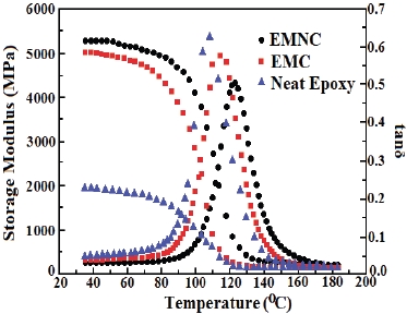
Figure 2 shows DMA curves for epoxy composites, which were cured at 120℃ for 2 h and postcured at 150℃ for 2 h. The storage modulus of the neat epoxy at 40℃ (in glass state) was 1,924 MPa, and that of EMC was 5,007 MPa, which was 2.60 times higher. That of EMNC was 5,254 MPa, which was 247 MPa higher than that of EMC. As the atmosphere temperature increased, the stor-
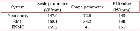
[Table 1.] Weibull parameters obtained from the flexural strength in Fig. 4.

Weibull parameters obtained from the flexural strength in Fig. 4.
age modulus (G′) decreased and abruptly dropped, and at the same time, the loss modulus (G″) abruptly increased in the glass transition state. The glass
transition temperature (Tg) was estimated from the peak temperature of tanδ, which was expressed as tanδ = G″/G′. The Tg value of the neat epoxy resin was 108.5℃,which was increased by the addition of micro-silica, and increased much more by the addition of nano-silicate. The Tg of the EMC was 112.7℃ and that of the EMNC was 122.2℃. When micro-silica was added to the epoxy matrix, the micro-silica could anchor the epoxy chains by the hydrogen bonding between silanol groups on the silica surface and hydroxyl groups in the epoxy matrix so that the mobility of the epoxy chains became disturbed. The anchoring effect increased when the nano-silicate was added, so the Tg value increased.
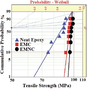
Figure 3 shows Weibull plots of tensile strength for epoxy composites, from which the parameters such as shape and scale parameters and B10 value were obtained. Here, the shape parameter could be obtained from the slope,which indicated the data distribution, and the scale parameter represented the tensile strength by which there was a 63.2% cumulative probability of failure. The B10 value referred to the tensile strength at which 10% would fail (90% would survive) under a given stress. The statistical analysis showed that the scale parameter of the neat epoxy was 88.2 MPa with the shape parameter of 14.4, and that of the EMC was 95.5 MPa with the shape parameter of 72.0. As the nano-silicate was added to the EMC, the scale parameter of the EMNC increased to 97.2 MPa with the shape parameter of 97.2. These meant that the anchoring effect of the micro-silica and nano-silicate took part in the immobility of polymer chains as explained in the DMA results of Fig. 2.
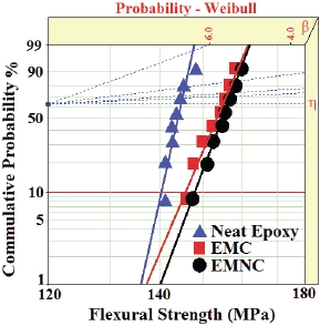
According to the addition of micro-silica and nano-silicate, the same tendency was observed in the flexural strength as shown in Fig. 4, and the Weibull parameters obtained from Figure 4 are listed on Table 1.
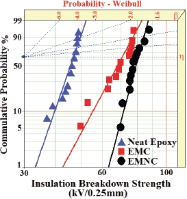
The statistical analysis data for the AC insulation breakdown strength tested at 30℃ are shown in Fig. 5. The scale parameter of the neat epoxy was 44.5 kV/0.25 mm in the neat epoxy with the shape parameter of 13.6, and that of the EMC was 71.4 kV/0.25
mm with the shape parameter of 8.2. As the nano-silicate was added to the EMC, the scale parameter of the EMNC increased to 80.6 kV/0.25 mm with the shape parameter of 16.7. The improvement of the scale parameter for breakdown strength was due to the electron blocking by the sphere-like silica particles, and there was more improvement by the sheet-like silicates. That is, if an electrical breakdown was initiated, it would be propagated rapidly and until finally breakdown occurred [19]. However, the silica and silicate particles retarded the breakdown rate. Therefore, the EMNC could be used as an excellent insulation material. In addition, the higher the gradient of the shape parameter became, the more homogeneous the breakdown strength data were. These results meant that the nano-sized silicates were evenly dispersed among the micro-silica particles and provided improved electrical breakdown characteristics to the micro-silica system.
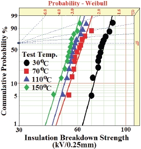
The effect of ambient temperature on the AC insulation breakdown strength in the EMNC system was studied at (●) 30℃, (■) 70℃, (▲) 110℃ and (?) 150℃, and the Weibull statistical analyses are shown in Fig. 6. The Weibull parameters are listed in Table 2. As the ambient temperature increased, the scale parameter increased. Compared to the result at 30℃, the AC breakdown strength at 70℃ was 20% lowered, and that at 150℃ was 28% lowered. This was because the mobilization of the epoxy chains increased at higher temperature.
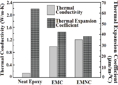
In order to apply the epoxy composites to as electrical insulation materials, thermal conductivity of the materials should be considered, because the generated heat during the operation of electrical equipment could cause polymer degradation [20]. Therefore, the generated heat should be removed from the core of the electrical equipment. When micro-silica was added to the epoxy matrix, thermal conductivity was largely increased, and much more increment was achieved by the addition of nano-
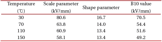
Weibull parameters for the AC insulation breakdown strength in EMNC system obtained from Fig. 6.
silicate as shown in Fig. 7. This meant that the micro-silica and the nano-silicate acted as heat transfer paths.
Furthermore, the thermal expansion coefficient (CTE) of the material should also be considered for insulation materials, because the heat-cycle during the service life could cause exfoliating between the epoxy casting part and the metallic parts [10]. Fig. 7 shows that CTE of the EMC was largely decreased, and much more decrement was achieved by the addition of nanosilicate.
Epoxy/micro-silica composite (EMC) and epoxy/micro-silica/ nano-silicate composite (EMNC) were prepared, and their mechanical, electrical and thermal properties were compared. The storage modulus of the neat epoxy at 40℃ (in glass state) was 1,924 MPa, and that of EMC was 5,007 MPa, which was 2.60 times higher. That of EMNC was 5,254 MPa, which was 247 MPa higher than that of EMC. Weibull statistical analysis showed that the tensile strength of the neat epoxy was 88.2 MPa, and those of the EMC and EMNC were 95.5 MPa and 97.2 MPa, respectively. The same tendency was observed in the flexural strength: those for the neat epoxy, EMC and EMNC were 147.9 MPa, 158.1 MPa and 159.2 MPa, respectively. Weibull statistical analysis revealed that the AC insulation breakdown strength of the neat epoxy was 44.5 kV/0.25 mm, and those of the EMC and EMNC were respectively 71.4 kV/0.25 mm and 80.6 kV/0.25 mm. The improvements in the thermal conductivity and thermal expansion coefficient were also achieved by addition of micro-silica and nano-silicate.