BaTiO3 based multilayer ceramic capacitors with Ni electrodes can be explained as 2-2 composites with different thermal expansion coefficient and sintering behaviors. To achieve the high capacitance and reliability of MLCCs, a homogenous Ni electrode configuration with high connectivity is required. We controlled the heating rates during sintering to achieve densification by suppressing grain growth. Experimental results revealed that a large heating rate gave high connectivity of Ni electrode, high capacitance, small dissipation factor, high breakdown voltage, and high reliability of MLCC chips.
BaTiO3-base multilayer ceramic capacitors (MLCCs) with high capacitance density are widely used for mobile equipment, and many other electronic facilities [1]. Among the various types of MLCCs, the Electrical Industry Alliance (EIA) mainly utilizes 0201 (0.6 mm × 0.3 mm) MLCCs with X7R temperature characteristics for communication industries [2]. To increase reliability ensuring high capacitance in MLCCs, the development of a homogeneous Ni electrode pattern was inevitable. Consequently, homogeneous and continuous Ni electrode and dielectric layers could enable high voltage operation suppressing leakage currents, dielectric breakdown and degradation. In fabricating
MLCCs with high reliability, the conditions of high density of BaTiO3 ceramic and continuous Ni electrode should be fulfilled simultaneously. To promote densification of BaTiO3-based MLCCs, nano size particles were utilized, or composition of BaTiO3 was intentionally modified with doping elements [3,4]. Beside ceramics, Ni electrodes should also have dense and continuous structure. This dense and continuous Ni electrode could be obtained by both modifying the composition of paste and controlling the sintering process, such as the heating rate. Beside the grain growth of BaTiO3 in dielectric materials and Ni particles in paste, the dielectric-electrode interfacial microstructure for ultrafine-grained Ni- MLCCs can also be controlled with the heating rate, so that many studies on heating rates have so far been conducted. Recently, a rapid heating sintering method has been extensively investigated to obtain high reliability ultrathin MLCCs [5-7]. However, studies on the effect of the heating
rate during the sintering process on the reliability and dielectric properties of MLCCs are rare. Therefore, in this study we will investigate how the heating rate during sintering process affects the interfacial microstructure between the BaTiO3 dielectric and Ni electrode and the associated dielectric properties of ultrathin BaTiO3 based MLCC.
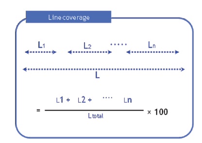
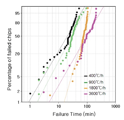
MLCC was made of hydrothermally synthesized BaTiO3 powder (Sakai Chem. Osaka, Japan), with a particle size of 0.2 μm. The dielectric was BaTiO3-based X5R-type material (with capacitance variation ± 15% in the temperature range from -55℃ to 85℃, which was formulated with chemical additives, such as MgO, Y2O3, MnO2 and BaO-CaO-SiO2 glass. The slurry was prepared by mixing the ceramic powder and polyvinyl butyral with ethanol/toluene solvent, and ball-milling for 24 h. The green sheet was prepared through a tape casting process. After printing the nickel electrodes, MLCC 0402 series chips (1.6 mm × 0.8 mm × 0.8 mm, 200 dielectric layers, 1.8 μm thickness green sheet) were laminated, pressed, and then cut into small pieces. To burn out the polymer binder in green chips, the green chips were held at 260℃ for 40 h in an air atmosphere. Next, the green chips were sintered up to 1,250℃ with different heating rates, ranging from 120 to 3,600℃/h in a reducing atmosphere. The sintered Ni-BaTiO3 MLCCs were then reoxidized in an atmosphere with a 20 ppm O2 atmosphere (pO2 level 10-9 atm) for 3 h at the temperature of 1,000℃. After grinding the sintered chips in a barrel, MLCCs were terminated with Cu electrode paste, followed by firing at 860℃ in an N2 -H2 gas mixture. Then, Ni and Sn were electroplated to the end terminals. The microstructure of sintered MLCC samples was characterized by scanning electron microscopy (JSM-6360, Jeol). The line coverage was calculated by commercial available software CERAPART (Science Solutions International Laboratory), based on the intercept method. Figure 1 shows a schematic of the line coverage calculation. The TCC (temperature-capacitance-characteristics) curves and capacitances were determined using HP 4284A precision LCR meter (HP, USA), at a test voltage of 1 V and frequency of 1 kHz. Capacitance measurements were taken in the temperature range from -55℃ to 125℃, by placing the MLCCs in a temperature chamber (S&A Inc., USA). The highly accelerated life test (HALT) was performed at 125℃ under 50 V DC voltage, which exceeds the nominal rated voltage for this type of capacitor by a factor of five. The increase in leakage current by one decade was used as a criterion for the failure time test. The failed population versus failure time was then presented on a double-log Weibull plot.
MLCC can be composed as a repeating 2-2 composite of thin

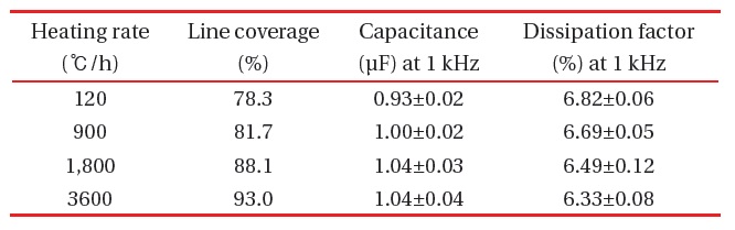
Line coverage, capacitance and dissipation factor of MLCC sintered with different heating rates.
dielectric layer between metal electrodes, and their capacitance can be expressed as Eq. 1.
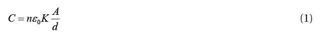
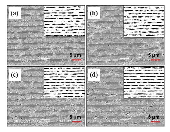
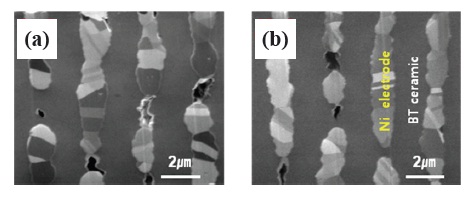
where n is the number of ceramic layers, εo is the dielectric permittivity in air, K is the dielectric constant of ceramics, d is the thickness of the dielectric layer, and A is the electrode area, respectively. As the thermal expansion coefficient and sintering behavior of the dielectric layer and metal electrode are different, it is difficult to achieve full densification of ceramic and high coverage of metal electrode, simultaneously. We controlled the heating rate during the sintering process of MLCCs, and SEM images of the MLCCs sintered with different heating rates, such as 120, 900, 1,800, and 3,600℃/h are shown in Fig. 2. The surface of MLCCs exhibit homogenous microstructure and the electrode line coverage strongly depends on the heating rates of sintering. In Table 1, the calculated coverage of electrode line shows that line coverage was improved with the heating rate 3,600℃/ h, and gave 93.0 % coverage.To obtain a clearer interfacial image between the BaTiO3 ceramic layer and Ni electrode, MLCC was treated with FIB, and images of Fig. 3 were obtained with higher resolution than in Fig. 2. Fig. 3 images did not completely answer the question of whether there were voids at the interface. However, it can be seen that the width of Ni electrode with a 120℃/h heating rate is slightly narrower than that with a 3,600℃/h heating rate. As the temperature was rapidly increased, both the Ba- TiO3 and Ni powder were densified in a short time, which did not allow for grain growth. Consequently, the Ni electrode did not shrink much, and could keep high coverage with a faster heating speed. The electrical properties of MLCCs were significantly dependent on the electrode coverage. The capacitance and dissipation factor of MLCCs with different heating rate are presented in Table 1. As expected in Eq. 1, the larger line coverage gives a
larger electrode area, resulting in larger capacitance and a smaller dissipation factor. However, the capacitance did not improve significantly with line coverage. Beside the electrode area, other variations, such as the internal microstructure, microchemistry of BaTiO3, and porosity of dielectric layers and inner electrodes, could affect the electrical properties of the MLCCs.
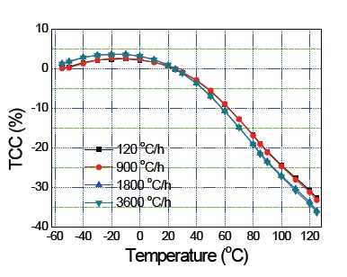
Figure 4 shows the TCC curve of sintered MLCC chips for different heating rates during sintering. The capacitance variation in the temperature range from -55℃ to 85℃ was between 4 and -19 % variations, which are slightly larger than the ± 15% of X5Rtype requirement. Here, a quantitative interpretation of the TCC behavior of MLCCs with different heating rates during sinter is beyond the scope of this paper, but we also assume that the final smaller grain size and dopant distribution inside the electric grain could affect the TCC behavior [8].
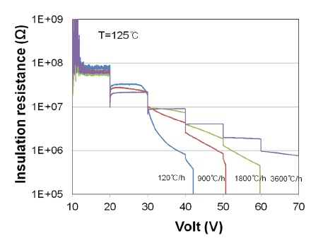
Figure 5 presents the electrical resistivity at high temperature under applied voltage versus time, for the MLCCs sintered with different heating rates. The high temperature resistance of the samples was measured at 125℃, by applying a DC voltage. Fig. 5 shows a systematic variation of the resistance degradation behavior for MLCCs of different heating rate condition. It was observed that higher heating rates lead to an improvement of resistance degradation, and higher breakdown voltage. As the larger heating rate gives a more continuous Ni electrode configuration, a more homogeneous electric field would be applied to the dielectric layer without breakdown. The effect of heating rate on MLCC degradation using a HALT has been studied [9,10], in addition to the time dependent degradation in insulation resistance characteristics associated with composition and processing conditions that strongly influence the degradation kinetics ofMLCC. Figure 6 shows a Weibull statistical plot of the failure rate distribution for the time variation under 50 V DC voltage at 125℃. This result shows a systematic improvement in the percentage of failure chips when a larger heating rate was applied. This improvement in failure rate could be attributed to the variation in the interfacial alloy layer of Ni electrode, which was described in the previous paper [11,12]. In the previous paper, it was shown that an alloy layer forms at the Ni-BaTiO3 interface while fast sintering, the alloy layer thickness is significantly reduced, and the Schottky barrier height is increased. The final electrode microstructure, interfaces and concentration of oxygen
vacancies near the Ni electrode are believed to be key parameters responsible for the electrical properties and reliability of ultrathin Ni-MLCCs.
The effect of heating rate during sintering on the connectivity of Ni electrodes and dielectrics was characterized, to achieve reliability and high capacitance in BaTiO3-Ni MLCCs. MLCCs with large heating rate gave high connectivity, high capacitance, small dissipation factor, high insulation resistance, and high reliability. The fast heating rate did not spare enough time for grain growth, but just accelerated the densification of BaTiO3 and Ni particles. A homogeneous electrode configuration with high connectivity allowed a homogenous electric field in the dielectric layer, and elongated the lifetime of MLCC chips. In our experiment, a 3,600℃/h heating rate gave a 93 % Ni electrode coverage. Optimization of the heating rate is required for fabrication of high quality MLCCs.