This study proposes a design for an airborne wind turbine generator. The proposed system comprises a cycloidal wind turbine adopting a cycloidal rotor blade system that is used at a high altitude. The turbine is mounted on a tethered balloon. The proposed system is relatively easier to be realized and stable. Moreover, the rotor efficiency is high, which can be adjusted using the blade pitch angle variation. In addition, the rotor is well adapted to the wind-flow direction change. This article proves the feasibility of the proposed system through a sample design for a wind turbine that produces a power of 30 kW. The generated wind power at 500 m height is nearly 3 times of that on the ground.
Wind energy is one of the most popular renewable energies in the world. However, the generation of a strong and steady wind flow is not easy to achieve. For this purpose, wind turbines are fixed on top of a tall tower; typically, in daytime, wind speed rises in proportion to the seventh root of altitude (Wikipedia, 2011b). Therefore, doubling the altitude of a turbine increases the expected wind speeds by 10% and the expected power by 34%, which means that the wind power generated is proportional to the cube of the wind speed. Moreover, at nighttime, or when the atmosphere becomes stable, doubling the altitude may increase wind speed by 20%-60%. However, the height of the tower is limited because of building cost involved. In general, to avoid buckling, doubling the tower height requires doubling the diameter of the tower as well, increasing the amount of building material by a factor of at least 4. This means that the cost of such a tower becomes 4.3 times for the tower and foundation construction only (Fingersh et al., 2006). For this reason, some novel concepts using wind energy at high altitudes have been studied. Kim and Park (2010) proposed a parawing on ships, in which the underlying concept is a tethered parafoil that pulls and tows a ship. The ship is equipped with hydraulic turbines below the water line. Another concept is the use of controlled tethered airfoils to extract energy from high-altitude wind flows (Fagiano, 2009). In this method, known as KiteGen?, the tether line makes a linear translational motion and drives an electric generator that is placed on the ground. Besides these two models, many other concepts for high-altitude wind generators can be found in journals and patents (Bronstein, 2011).
Although the idea of using high-altitude wind energy is very useful, there exist several technological and policy barriers (Bronstein, 2011), such as electricity transmission, system safety, and cost effectiveness. The electricity from the airborne power generator can be transmitted by a tether cable, which is reliable, cost-effective, and low-weight. A high-performance synthetic fiber, such as vectran or aramid with an aluminum conductor, is an affordable option for the 100~200 kg/km tether cable (Bronstein, 2011; Kang, 2008). System safety is another big engineering design problem for the airborne wind turbine. The main source of system failure can be the rotating parts of the wind turbine. After studying many different turbines, the authors concluded that the current horizontal-axis wind turbine is not appropriate for airborne power generators. The tips of the horizontal-axis wind turbine blades make a big circle around the rotating center. This rotating arch can unexpectedly collide with any part of the airborne wind turbine and result in system failure. For this reason, vertical-axis type wind turbines also known as the cycloidal wind turbines are proposed as an alternative in this study.
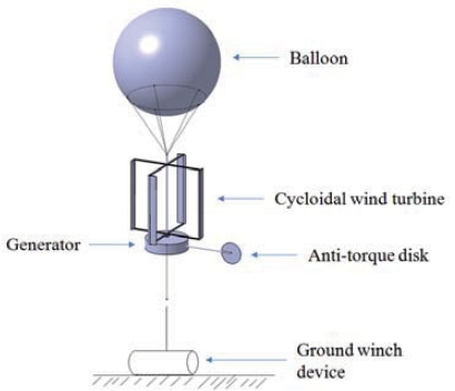
In this article, an airborne cycloidal wind turbine is proposed as a new high-altitude wind power system. This method is relatively easier to be realized and stable because the rotor and electrical generator are located below the balloon. The unique characteristic of the cycloidal rotor is that the rotating axis and blades are parallel to the tethering cable, which in turn increases the system stability. The efficiency of the rotor can be enhanced by varying the cycloidal blade pitch. In addition, the rotor is well adapted to the wind-flow direction change. Figure 1 shows the overall conceptual view of the proposed system. The balloon is filled with buoyant helium gas to produce lift. The cycloidal wind turbine with electric power generator is located below the balloon. A set of winch devices holds the airborne system using the tether line on the ground. A disk is attached to the generator for the purpose of balancing the torque caused by the rotation of the cycloidal blades.
2. System Requirement and Wind Environment
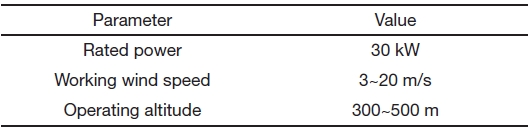
As a feasibility analysis model, 30 kW class wind turbine is
designed. Table 1 shows the top-level requirements. The cutin and cut-out wind speeds were determined considering the characteristics of the cycloidal rotor. The maximum operating altitude was limited to 500 m by the tethering cable weight and statistical wind speed profile data.
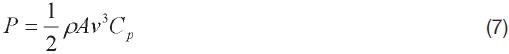
The wind profile power law defines the relationship between wind speeds at two different heights. This law is often used in wind power assessments. The following equation expresses the profile of wind speeds with reference to the altitude (Wikipedia, 2011a).
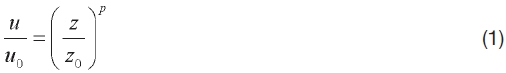
where, u is the wind speed and z is the altitude.
The exponent value is an empirically derived coefficient that varies depending on the stability of the atmosphere. For neutral stability conditions, p is approximately 1/7 or 0.143 (Wikipedia, 2011a). Although wind conditions vary with regional differences, the profile pattern remains almost similar. This means that wind power becomes approximately 2.7 times at 500 m height compared with that at 50 m height. Moreover, research by Archer and Caldeira points out that rapid increase in wind power density with altitude occurs between 80 and 500 m (for median winds, +0.25 W/m2 for each meter increase in altitude) (Archer and Caldeira, 2009). This research also suggests that for several sites in Europe, there may not be much benefit in going higher than 500 m, unless the height reached is more than 2,000 m. This is one factor that determines the operating altitude as shown in Table 1.
Another parameter to be considered in wind environment is the wind speed distribution. For this purpose, the Weibull distribution is widely used.
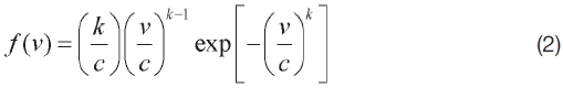
where k is a shape parameter and c is a scale parameter.
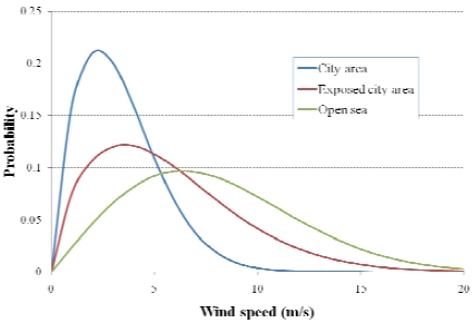
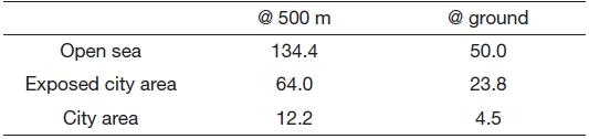
Figure 2 shows the wind speed frequency distribution for a given set of wind data recorded in a period of 30 years in Hong Kong (Lun and Lam, 2000). The three curves represent three different types of locations?an open sea area (e.g. an island), a completely exposed area (e.g. high up in the city

System requirement
center), and a city area within the territory. The mean wind speeds become 7.0, 4.5, and 2.7 m/s, respectively, for the aforementioned locations. Applying a value of 0.143 as the exponent value in Eq. (1) and assuming a reference height of 50 m, the wind speeds at 500 m height become 9.7, 6.3, and 3.8 m/s, respectively, for the three types of locations.
3.1 Characteristics of cycloidal rotor
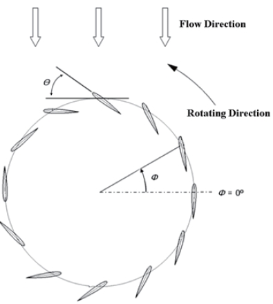
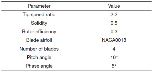
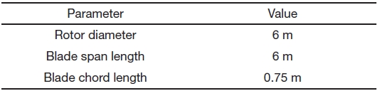
The cycloidal wind turbine shown in Fig. 1 adopts the cycloidal blade system for variable blade pitch control (Yun, 2004). Figure 3 shows the schematic view, which consists of several blades rotating with periodic pitch angle variation. The characteristics of the rotor could be changed by variations of the pitch angle (θ) and the phase angle (φ), which is defined as the location of maximum pitch angle. This mechanism has also been applied to aircraft and marine propulsion systems (Bartels and Jurgens, 2004; Boschma, 2001; Hwang, 2009). Although finding optimal values of the rotor is important, in this study, several aerodynamic and structural variables were adopted without further parametric studies, with reference to the results of previous research (Hwang et al., 2009). Table 2 shows the determined values. The tip speed ratio, which is defined as the ratio between rotor blade tip speed and windflow speed is assumed to be 2.2. This value determines the rotor solidity. Rotor solidity is defined as the ratio between the area of the blades and rotor cylinder area. This variable is a function of the number of blades, blade chord length, and rotor diameter. When the rotor solidity is higher, the tip speed ratio becomes smaller. In the cycloidal rotor, slower rotation is preferable because of the centrifugal force on the blades. The rotor efficiency is assumed to be 0.3 in this research. This value is conservative compared with the result
[Table 2.] Selected rotor design parameters

Selected rotor design parameters
of the previous research; however, 30% is acceptable because of the consideration of uncertain factors. In a cycloidal rotor, in general, a symmetric airfoil is used, and a relatively thick airfoil is preferred for structural reasons. The blade pitch angle should be large, more than 30° when the rotor starts rotating; however, it becomes smaller, almost as small as 10° during steady rotation.
3.2 Aerodynamic and structural analysis of cycloidal rotor
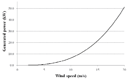
On the basis of the selected design parameters, the rotor configuration was determined as shown in Table 3. Under these conditions, power generation using the cycloidal wind turbine was estimated as shown in Fig. 4. The rated power 30 kW, which is a requirement of this system, could be achieved at 17 m/s of wind speed. The rotating speed of the rotor is approximately 120 rpm for the power generated.
When the cycloidal wind turbine is in operation, the dominant load on the blades is the centrifugal force. Assuming that blades are simply supported at both ends, displacement can be calculated using the following equation:
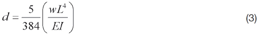
where w is the distributed load and L is the blade span length.
Figure 5 shows the blade section view. As mentioned, the airfoil NACA0018 was used in this study, and it has one spar at 1/4th chord position. The weight of one blade of aluminum alloy is approximately 24.5 kg. The maximum displacement is calculated as 0.187 m from Eq. (3) under a uniformly distributed load and maximum operating wind condition. Although this calculation is very simple, it is necessary and sufficient to check whether the rotor blade structure design is appropriate or not.
When the cycloidal wind turbine is rotating, an antitorque device would be necessary on the electric power generator. For this purpose, a simple circular plate is attached as shown in Fig. 1. The position and area of the disk could be calculated easily using the following equations:
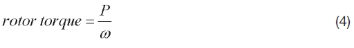
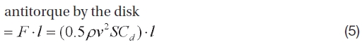
where ω is rotor rotation speed and P is rotor power. In Eq.
[Table 3.] Rotor design confi guration
Rotor design confi guration
(5), S is disk area and l is disk location.
Resulting values of Eqs. (4) and (5) should be the same; therefore,
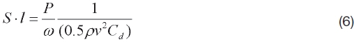
The result of Eq. (6) is independent of the wind speed and rotor rotating speed. Assuming a drag coefficient of 2.0 for the disk, the area of the antitorque disk is calculated as 1.2 m2 when it is at a distance of 6.0 m from the rotating center.
3.3 System weight and balloon sizing
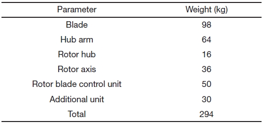
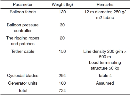
On the basis of the rotor design and previous research, the whole system was roughly modeled using the 3D-modeling program CATIA. Table 4 shows the component weight estimation of the cycloidal wind turbine. Total weight of the rotor is almost 300 kg.
A spherical balloon was designed to make the 300 kg weight rotor airborne. The balloon is filled with helium gas to generate a static lift and tethered to the ground by a cable. The design altitude for the balloon is 500 m. The air density at 500 m altitude is 1.167 kg/m3 when the ground temperature is 15℃. The air density at 15℃ is 1.225 kg/m3 at the ground,
[Table 4.] Cycloidal wind turbine weight estimation

Cycloidal wind turbine weight estimation
[Table 5.] The balloon system weight estimation
The balloon system weight estimation
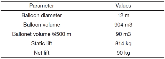
while the helium density is 0.169 kg/m3. The static lift by 1 m3 of helium is about 1.0 kg at 500 m altitude (Khoury and Gillett, 1999). The total weight of the tethered balloon system can be divided among three components: balloon, tether cable, and payload and comprises the weight of the balloon fabric, pressure control system, and the rigging cables and patches. The weights are summarized in Table 5.
Usually, a tethered buoyant balloon is designed to have a 10%~15% additional lift to the total weight of the balloon system. The envelope of the balloon should be divided into two different cells: One is the helium cell, which is used to store the buoyant gas, and the other is the ballonet, which is used for the pressure control of the balloon (Khoury and Gillett, 1999). A ballonet is used to maintain the inner pressure of the balloon envelope, which is caused by ambient temperature and pressure change of the surrounding air. Helium leakage can be a major source of pressure loss in the envelope. The volume of the ballonet is 10%~30% of the entire balloon envelope. For the tethered balloon used in the airborne wind turbine, a ballonet volume of 10% is enough. The major characteristics of the balloon can be summarized as shown in Table 6.
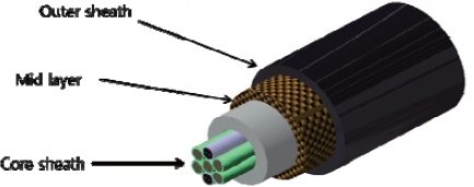
The tether cable is about 20 mm in diameter and comprises three different layers as shown in Fig. 6. The outer sheath of the cable is made of a polyurethane coating, which protects it from ultraviolet light and abrasion and prevents water absorption. The middle layer is made of synthetic fibers such as aramid or vectran. The midlayer carries loads that are transferred from the balloon to the ground. The core layer is made of a metal wire, which is used for transferring electric current. The number of metal wires are 4~6. Three wires are used for transferring electric current and another is used for electric grounding and lightning protection, the other wire is redundant and it is used when some cables are broken in operation. As shown in Fig. 6, one or two communication cables can be added to the core layer for controlling and monitoring the balloon and the airborne wind turbine system. If a wireless communication system is used, these cables can be omitted. When the density of the tethering cable is 0.2 kg/m, it becomes approximately 100 kg for the 500 m long line. Overall tether cable weight can be assumed
[Table 6.] The balloon system characteristics

The balloon system characteristics
as 150 kg including the weight of a load termination bracket. The load termination bracket is used to transfer loads from the balloon to the tether cable (Kang, 2008).
Although the electrical power generator has not been designed as yet, the weight including some other related units is assumed to be 100 kg. A summation of all these weights gives a total payload of 724 kg. The volume of the exactly spherical-shaped balloon is 904 m3 with a 6 m radius. The weight of this balloon is estimated on the basis of Kang (2008).
Table 5 shows total wind power generation capacity at three regions for a period of 1 year. The wind profile distribution in Fig. 2 was used for this calculation. The reference height from the ground is assumed to be 50 m. Assuming that the exponent value in Eq. (1) is 0.143, the wind speed distribution at 500 m height was obtained; then wind power was calculated within the operating wind speed range according to the following equation:
where Cp is the rotor efficiency, which is assumed as 0.3 in this study.
As indicated, if the proposed wind turbine system is used, it will generate a much larger energy. The additional energy generated is approximately 84, 40, and 8 MWh per 1 year, respectively.
This article describes an airborne cycloidal wind turbine mounted using a tethered balloon. The preliminary study about high-altitude cycloidal wind power generation system in this article shows that it is possible to obtain much more wind energy. The sample calculation shows that the amount of additional energy becomes almost 200% of that at ground level. If we can obtain 80 MWh more of electrical energy in 1 year as indicated in Table 7, and if the electricity per
[Table 7.] Power generation capacity (MWh/year)
Power generation capacity (MWh/year)
household is assumed to be 360 kWh/month, which is the average usage in Korea in 2009, this additional amount of energy will serve approximately 20 houses. The rotor size in Table 3 is relatively small for a town of approximately 100 houses; however, the proposed system could be extended to any number of houses and can be regarded as a thoroughly feasible plan for an alternative electric power generation system.