In recent years, interest and research in the highlyagile turn, with regard to combat, has grown. High angle of attack missiles can increase the off-boresight capability and maneuverability directly connected with tactical performance.
To maximize missile performance, appropriate autopilot command structure is required for each mission phase, including: launch, agile turn at high angle of attack, midcourse, and endgame (Wise and Broy, 1998). This is particularly important as missile dynamics undergo significant changes during the course of the flight; this paper focuses specifically on the agile turn phase. While a missile is operating at a high angle of attack, the angle of attack command?unlike the conventional acceleration command?is needed for rapid and effective control.
The simple and conventional control method for missiles is the linear controller, but it requires gain scheduling at multiple design points. In Wise and Broy (1998), agile missile dynamics and the linear control commanding angle of attack have been studied. Mehrabian and Roshanian (2006) introduced application of linear parameter varying modeling and control for a highly agile missile. Many gain scheduling techniques in missile autopilot design have already been studied (Lawrence and Rugh, 1993; White et al., 1994) for nonlinear model. Because of high nonlinearity in the agile turn, nonlinear control techniques are also employed in order to design control law (Innocenti, 2001; Menon and Yousefpor, 1996; Thukral and Innocenti, 1998).
The purpose of this paper is to introduce the design of the angle of attack controller using the pole placement approach for the high angle of attack missile. This technique is proposed to overcome difficulties in gain selection and scheduling in nonlinear models. This research deals with a nonlinear missile model in the pitch plane; the equation of motion is discussed in Section 2. In Section 2, the missile model specifications for autopilot design are listed. Section 3 introduces the angle of attack control system. the controller configuration designed by the pole placemenr method, as well as the process of gain computation, are explained. Section 4 shows gain scheduling and numerical results. Finally, conclusions are drawn in the final section.
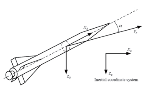
Nonlinear equations of motion describing missile flight are used in the autopilot design. A body coordinate system and an inertial coordinate system are employed to derive the equations of motion as shown in Fig. 1. Under the assumption of rigid body, no gravity, no roll rate, and zero roll angles in the pitch plane, the translational and rotational dynamics of the symmetric missile are written as follows:
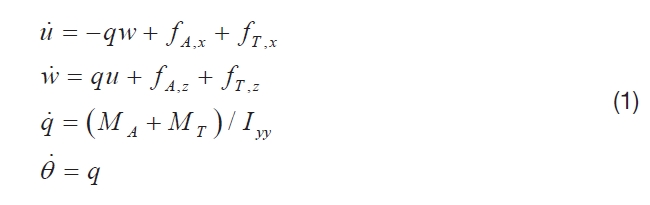
, where u and w indicate the missile velocity components along the X and Z body axes; q the pitch rate; fA the accelerations by the aerodynamic forces; fT the accelerations by the propulsion system; MA and MT the pitch moments produced by aerodynamic force and thrust; Iyy the moment of inertia about the pitch axis; and ? the pitch angle.
The angle of attack dynamics are modeled as follows:
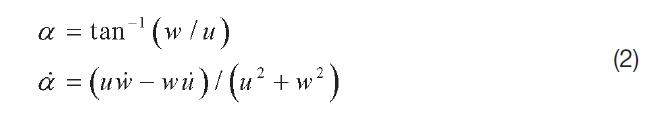
The missile used in the design controller has performances
and specifications as follows :
1) Flight/maneuvering ranges
- Mach number: 1.0 to4.0
- Altitude: 0 km to20 km
- Total angle of attack: 0 deg to 90 deg
- Maneuvering acceleration: 0 g to50 g
2) Missile specifications
- Mass: 92.0 kg
- Moment of inertia: Iyy = 59.8043 kg.m
3) Actuator (control fins)
- Damping ratio: 0.7
- Natural frequency: 30 Hz
- Deflection limit: 28 deg
3.1 Angle of attack autopilot configuration
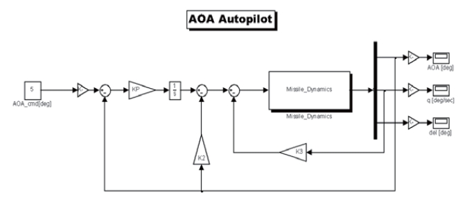
For the agile turn of missile, the autopilot tracking the angle of attack appears in Fig. 2. In this system, the pitch rate and the angle of attack are used for feedback in the controller. The concept of the autopilot in this paper comes from the threeloop autopilot (Zarchan, 2007). The three gains, Kp, K2, and K3, must be chosen to satisfy desired parameters, which are closed-loop frequency, system damping, and time constant.. The selection of the adequate closed-loop frequency and damping ratio can help avoid many stability problems, and the system time constant can select the response speed, as mentioned in Zarchan (2007).
The design criteria are set as:
- Settling time should be less than 0.2 seconds
- Phase margin should be greater than 30 deg
- Gain margin should be greater than 6 dB
According these conditions, three design parameters are:
- Time constant τ: 0.07 seconds
- Damping ratio ζ: 0.6
- Closed-loop frequency ω: 85 rad/s
3.3 Gain selection by pole placement approach
By selecting the frequency ω, damping ratio ζ, and time constant τ, the closed-loop poles and gains should be chosen. From Fig. 2, one can see that the relationship between the output angle of attack and the command is:
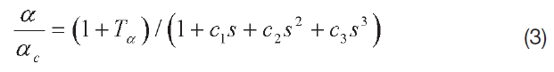
, where
c1 = 1 / K aK p + K 2 / K p + T a + K qK3 / K aK p
c2 = 2ζ AF / ωAFKaKp + K 2T a / K p + K qK 3T q / K aK p
c3 = 1 / ωAF2K aK p
To represent three gains with desired parameters, the closed-loop transfer function can be written in the 3rd order system, of [ed: did you mean or?] with the following form:
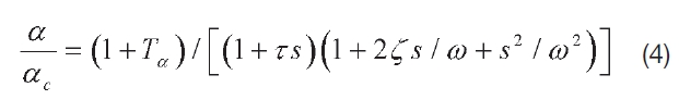
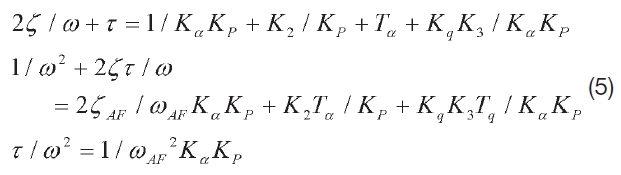
The two transfer functions, Eqs. (3) and (4), are equivalent if the denominators are the same. Therefore, three linear and simultaneous equations should be structured as follows:
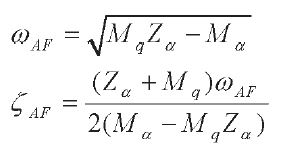
The airframe characteristics, ω
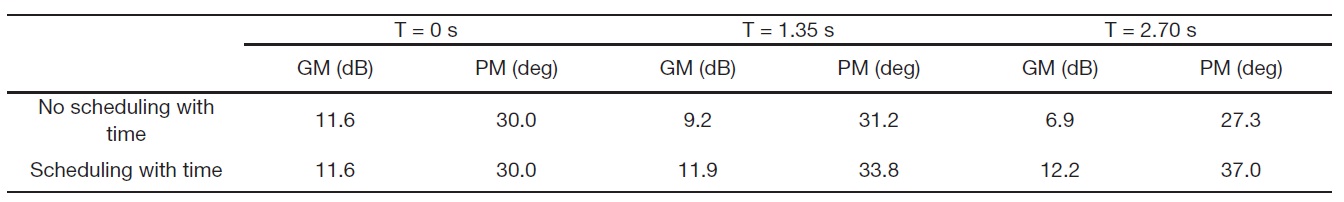
[Table 1.] Analysis of stability margin (M = 2.0 and α = 10 deg)

Analysis of stability margin (M = 2.0 and α = 10 deg)
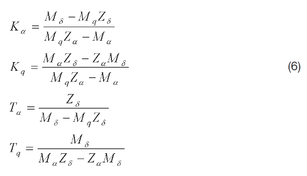
From Eqs. (5) and (6), the autopilot gains can be derived as follows:
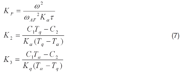
, where
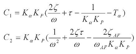
In Eq. (7), three gains are expressed as aerodynamic coefficients and desired parameters, ζ, ω, and τ. This autopilot technique alleviates the problems with gain tuning process in the design of linear controller.
The performance of a high angle of attack autopilot should be verified by nonlinear simulations because of nonlinearity and fast variation of parameters.
To cope with the nonlinear plant, a gain scheduled controller was used in the simulation. The procedure is outlined in Lawrence and Rugh (1993) and White et al. (1994). First, the family of trim point is determined, and a family of linear controllers is designed to achieve the specified performance at each operating point. Next, the gain is computed at each operating point using Eq. (7), derived in previous section. The final step is checking the performance of the controller.
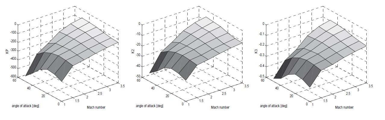
In this study, the variables for gain scheduling are set angle of attack, and Mach number M. The set of 36 equilibrium points is chosen, corresponding to the value of:
This selection is based on the result of trajectory optimization (Lee et al., 2009). There should be a command for the angle of attack autopilot designed in this research. The autopilot design technique by pole placement approach helps rapidly make a gain matrix, despite many scheduling points highlighted in this paper. With regard to applied linear interpolation, 3 controller gains are depicted in Fig. 3.
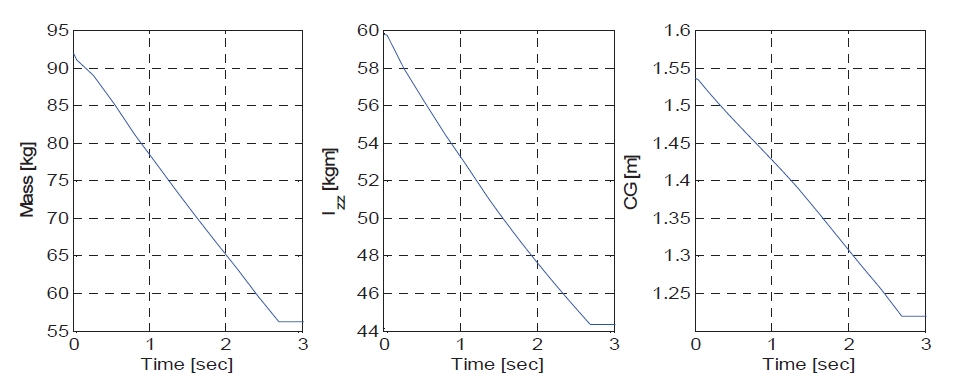
Considering that the mass is rapidly varied during the
boost-phase, we added the scheduling parameter relative to mass variation. Figure 4 shows that the mass linearly decreases with time, and similar effects were observed for the center of gravity and the moment of inertia. These characteristics have decisive effects on longitudinal dynamic behavior. Time is therefore an additional scheduling parameter considered in this paper. Time is divided into three sections: before start of ignition (0 s), mid-time (1.35 s), and after the end of ignition (2.70 s).
t∈{0s, 1.35s, 2.70s}
To check the stability, we computed the stability margin at some possible flight conditions. Table 1 shows the stability margin at the condition at which is M = 2.0 and α = 10 deg. The first row represents the stability margin without time scheduling and the second row includes time scheduling. The stability margin after time scheduling increases as compared with the first case. Also, time scheduling helps some unstable models to stabilize.
For the simulation, the non-linear model, short-range air-
to-air missiles (SRAAM), from Zipfel (2000) is implemented in MATLAB-SIMULINK. Initial operating point are set as follows:
α = 0° and M = 1.0
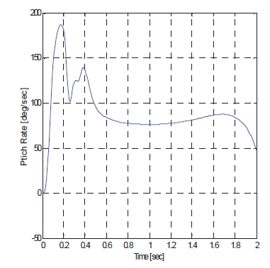
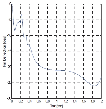
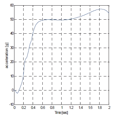
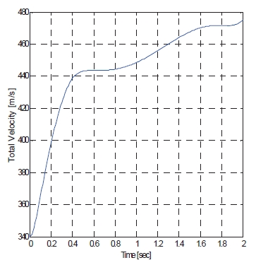
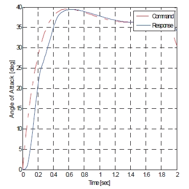
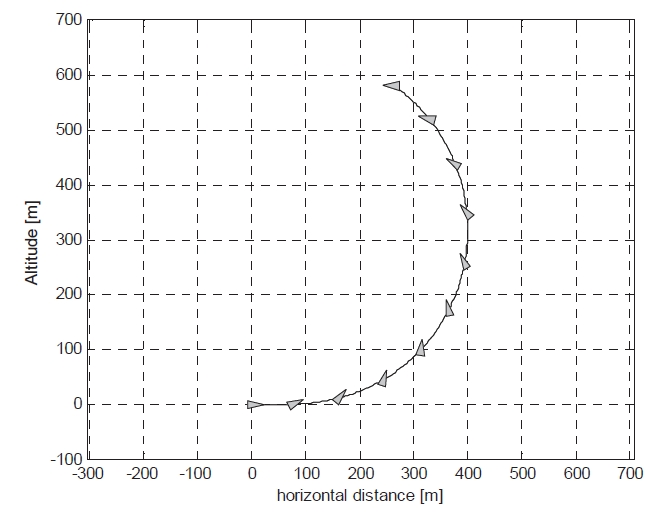
The angle of attack command is from Lee et al. (2009), as mentioned, and this simulation can validate autopilot performance in the agile turn scenario. The total command time is 2 seconds until heading angle reaches from 0°to 180°, and simulation is performed during this range. Total velocity and acceleration of missiles are shown in Figs. 5 and 6. Also, the time history of the angle of attack response, pitch rate, and fin deflection in Figs. 7-9 are presented. This rapid response and low steady state error shows that the control system designed in the present study meets desired performance. The resulting flight trajectory of missiles in this scenario is shown in Fig. 10. The solid line shows the trajectory, and triangles represent the attitudes of the missile at each point.
In this paper, the angle of attack controller for an agile turn missile in the pitch-axis is designed. The proposed design scheme, with a pole placement approach, is well-suited for gain scheduling techniques, as it eases the designer? burden in selecting controller gains at each operating point. In addition, scheduling variables which include the angle of attack, dynamic pressure, and time capture the nonlinearities of the missile dynamics and increase stability margins during the boost-phase.
The performance of the proposed control scheme has been shown in the simulation results. Future work might include systematically implementing the gain scheduling method and extending the design to a three-dimension case with a thrust vectoring control system.