In recent years, the performance of flight vehicles, including manned aircrafts and unmanned air vehicles (UAV), has been improved and the operability of both commercial and military vehicles has been upgraded. As such, thermal management of vehicles has become more important than ever. Cooling systems for thermal management are often provided to vehicles designed to fly at high subsonic or supersonic speeds, although heating systems are also required (Moir and Seabridge, 1992). The thermal problem caused by some heat sources in flight needs to be solved in order to successfully cool down the vehicle and its onboard systems. The heat from these sources should be transferred to a vehicle’ s heat sink and then completely expelled from the system. The air around the vehicle and onboard fuel are examples of available heat sinks. There are a number of potential causes of excess heat in a vehicle, such as solar radiation, the electricity-generation system, and avionic equipment. Typically, an air/fuel thermal management system can be considered in association with the heat sink to be used. However, the use of ram air as a cooling medium has some limitations, since the temperature of it increases with airspeed and soon exceeds the required value for cooling the vehicle’ s components (Moir and Seabridge, 1992). Fuel is more effective as a heat sink than ambient air, due to its higher heat capacity and heat transfer coefficient. Therefore, using fuel as a heat sink is very effective.
The primary purpose of a UAV’s fuel system is to supply fuel to the engine. In order to use the fuel as a heat sink, the UAV fuel system must also be designed to manage the thermal problem. The fuel temperature in a UAV changes with flight conditions. Thus, it directly affects the operating environment of the UAV’s onboard systems and components that use the fuel as a heat sink. Therefore, the design and analysis of the flight vehicle’s thermal management system using fuel has to be undertaken with careful consideration of the temperature control requirements of every onboard system, component, and engine.
In the present study, a model of a thermal management system coupled with a fuel supply system is employed. A military vehicle UAV is selected as the vehicle model. Analysis of the engine temperature is not included in this report because the engine is regarded as an independent unit from the UAV fuel system. Based on this analysis, the transient fuel temperatures in flight as well as the solar radiation effect on the ground are predicted for each separate fuel tank. Variations in the fuel temperature for a given flight pattern are analyzed, with particular attention paid to a fuel supply system including the forward and rear fuel tanks.
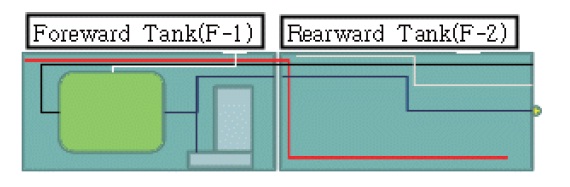
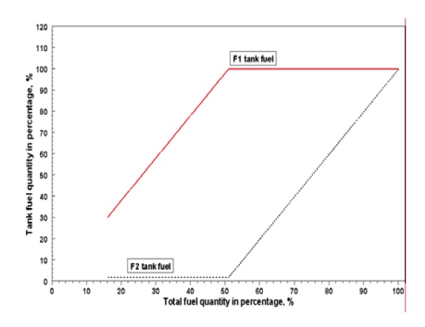
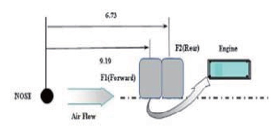
A schematic of the UAV fuel system considered in the present study is shown in Fig. 1. The fuel is stored in two fuel tanks, designated as F-1 and F-2. The electrical fuel boost pump is installed in F-1l is consumed sequentially, initially from F-2 and then from F-1, as shown in Fig. 2. Both tanks are connected by a transfer tube, through which the fuel is moved via pressurized air.
After the F-2 tank becomes completely empty, the fuel of
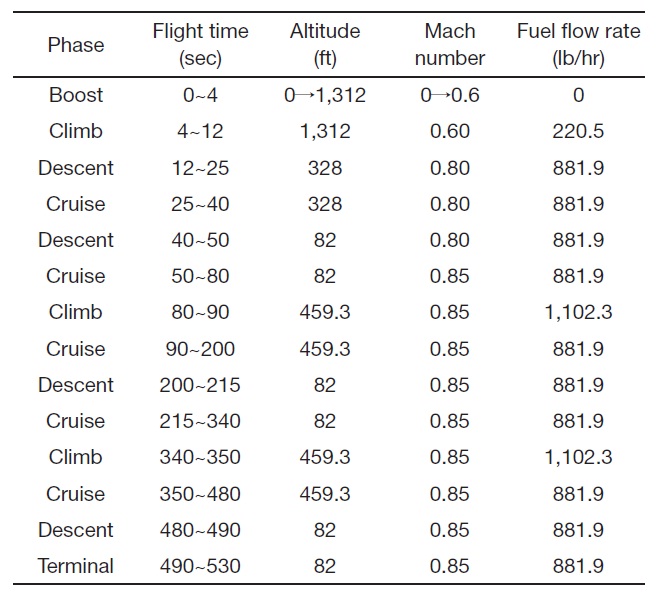
F-1 begins to flow out. The fuel in F-1 is fed to the engine via an electrical boost pump. The average flow capacity of the boost pump is 400 kg/h in all flight conditions. The fuel flow rate is aff ected by the flight condition, as shown in Table 1. When the fuel is pumped from the F-1 tank, it passes through the pipe to the engine.
The flight mission profile of a UAV consists of a number of phases. Each flight phase is characterized by the flight time as well as by the typical flight parameters, such as altitude and Mach numbers (Hunecke, 1987). The flight mission model considered in the present study is shown in Table 1.
3.1 Governing Equations and Numerical Analysis
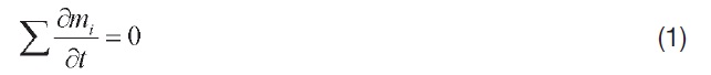
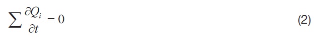
The governing equations used in this analysis are the continuity and energy conservation equations for fuel, as depicted here:
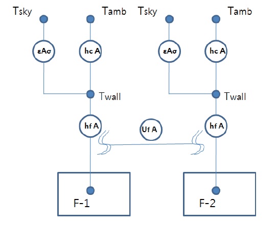
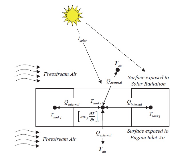
As shown in Fig. 3, the major heat transfer mechanisms related to temperature variation in a fuel tank are as follows:
External heat transfer from the atmosphere including solar radiation?Qext, Qsolar

Mission profile
Internal heat transfer through the tank wall wetted by the fuel in adjacent fuel tanks?Qint
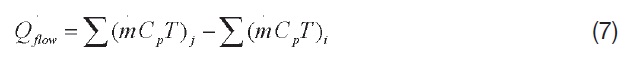
Thermal energy flux associated with the fuel flow through tanks?Qflow
Heat generation caused by the heat source (electrical fuel boost pump) in a tank?Qsource
With the mechanism of heat transfer in Fig. 3, the basic energy conservation equation is represented as:
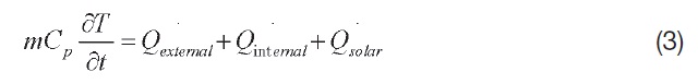
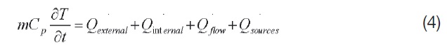
Equation (3) is used to solve the problem of solar radiation. Equation (4) is used for transient analysis. The right-handed terms of Eqs. (3) and (4) are calculated as follows;


Equation (5) represents heat transfer between the fuel and atmosphere. Equation (6) is used to analyze heat transfer between the fuel tanks. The UAV fuel systems in Fig. 1 can be described as a conductance capacitance network analysis, with nodes for heat transfer as shown in Fig. 3. This system also contains a thermal network as shown in Fig. 4, including
the fuel tanks and the fuel flow path.
There are two types of nodes to be considered for numerical calculation: diff usion nodes and arithmetic nodes. A fuel tank can be regarded as a diff usion node. An arithmetic node is defined as a node in which heat capacitance is not accounted for. The ambient air temperature and the junction of the fuel pipe are arithmetic nodes. The fuel temperatures in the tanks have been calculated to achieve transient solutions at each node. These nodes are thermally-interconnected with each other by the conductors. The purpose of this is to reflect the heat and mass transfer caused by the fuel flow in the fuel system as well as environmentally induced aerodynamic heating effects. The conductor has its own conductance, which is represented by the mass flow rate multiplied by the specific heat.
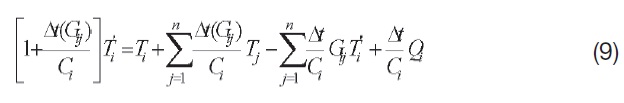
The SINDA/G code, employing an explicit method called the modified Dufort-Frankel scheme, is used to calculate the finite diff erence (Network Analysis Inc., 1996). To perform numerical analysis for the diff usion nodes, the energy equation of Eqs. (3) and (4) are presented as the following finite diff erence equation. Designated Eq. (9), this involves three time levels and their corresponding temperatures:
After the calculation of the diff usion nodes, the temperatures of the arithmetic nodes are computed. The temperature of an arithmetic node is determined by the Laplace or Poisson equations (Network Analysis Inc., 1996) and calculated using the Gauss-Seidal method. The arithmetic nodes are calculated by iteration until the convergence criterion, Eq. (10) is achieved:

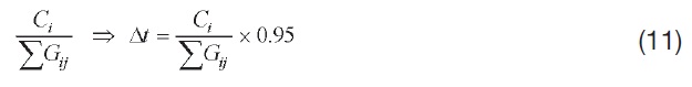
The stability of each diff usion node is discriminated by Eq. (10). The computational time step size used in the present analysis begins at 0.05 minutes. This initial time step size is used in order to avoid the startup error caused by the use of a large computational time step size. Upon successful computation of a chosen time step size, the current time step size of 0.05 minutes and a temporarily estimated time step size for the next computation, obtained by Eq. (11), are compared. The smaller of the two time step sizes is chosen to be a time step size for the next calculation.
The aviation fuel used in this study is JP-8, MIL-PRF-83282 fluid (Coordinating Research Council, 1988). The initial fuel quantity is full for both the F-1 and F-2 tank. Additionalluy, the following assumptions have been used for the initial fuel temperature analysis, including solar radiation:
The UAV is assumed to maintain level flight. Hence, the fuel in a tank decreases during flight, and the corresponding fuel-wetted area changes. As such, the heat transfer can be calculated on the basis of the area wetted by the fuel in tanks.
Free-stream air flows normally from the forward to rearward of the UAV and side-wind is not considered.
The thermal resistance of conductive heat transfer through the walls of the tanks and tubes is negligible in comparison to the thermal resistance of convective heat transfer.
The heat transfer between the ambient air and the fuel in a tank is ignored because the thermal capacity of the fuel in a tank is much greater than that of the air.
Heat transfer between the ambient air and the air in each component bay is negligible because it is closed by the UAV structure.
The view factor is taken to be 1, and so the outer surface of a fuel tank is always exposed to solar radiation
The lower surface of a fuel tank is 40% of the size of its
upper surface.
The absorption and emissivity of a fuel tank are 0.8 (F-16 Aircraft experiences).
The effective sky temperature is 40 oF
The heat transfer rate between the ambient environment and the fuel tanks caused by external aerodynamic heating must be calculated. To do this, the adiabatic wall temperature and the total temperature of the free-stream are used as the characteristic temperatures. The hot day ambient temperature data, with a 20% probability hot day ambient temperature data (US Deptartment of Defense, 1997) are used to calculate the adiabatic wall temperature and heat transfer coefficient between the ambient air and the fuel tanks. This is done using the following Eq. (12), where turbulent r is

(Kreith and Black, 1980).

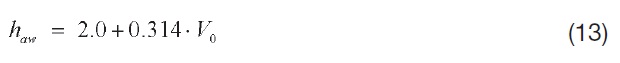
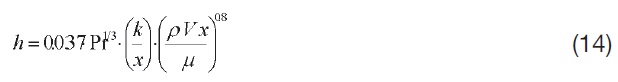
The convective heat transfer coefficients are considered in order to calculate the heat transfer between the above characteristic temperatures and the fuel tank surface. Equation (13) is an empirical equation representing the above coefficients as a function of free-stream air velocity (V0 m/ sec) when the UAV is on the ground (Society of Automotive Engineers, 1990). In flight phases, Eq. (14) is employed for the heat transfer coefficient of turbulent flow on a flat plate, as suggested by Eckert (Schlichting and Kestin, 1979).
The distance from the UAV nose to the center of each tank is the characteristic length used for calculating the coefficient of heat transfer between the adiabatic wall temperature and the tank surface. Figure 5 shows the major characteristic lengths used to calculate the coefficients of heat transfer between the ambient air and the rind of fuel tanks.
The amount of fuel in the tanks is continuously decreasing during flight. As such, the heat transfer area of the walls between the fuel tanks and the ambient air decreases in line with fuel consumption, as shown in Table 2. The wetted surface areas between the F-1 tank and the F-2 tank also
[Table 2.] Heat transfer area (ft2)
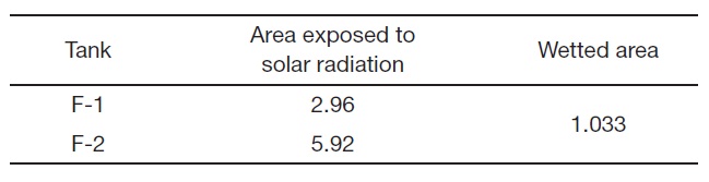
Heat transfer area (ft2)
change as a function of the remaining fuel in the tanks. The areas exposed to solar radiation are 2.96 ft2 for F-1 and 5.92 ft2 for F-2, respectively. The wetted area between F-1 and F-2 is 1.033 ft2. The electrical fuel boost pump of the fuel system gives some heat flux to the fuel system. This is because the driving motor of the pump dissipates 364 W of the heat in F-1.
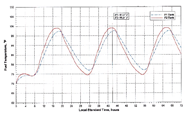
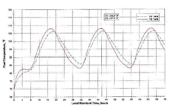
From this analysis, the initial temperature of the fuel tank is predicted in the case of 72 hours of exposition at 20%- and 1% - probability hot day conditions (US Deptartment of Defense, 1997). The variation of fuel temperatures of each fuel tank are shown in Figs. 6 and 7. As shown in Figs. 6 and 7, the fuel temperatures in F-1 and F-2 are stabilized on the second day. It takes 19 hours for F-1 and 17 hours for F-2 to approach the first peak temperature. The peak temperature of F-2 is a little higher than that of F-1. The reason for this is that the surface area of F-1 is larger than that of F-2. Thus, the heat transfer and solar radiation of F-1 are more active than those of F-2. Table 3 represents the resultant maximum temperatures.
For a given flight condition shown in Table 1, transient
fuel temperatures of the tanks are predicted in the design stage of the fuel system. The initial temperatures of the fuel tanks are determined as the values of Table 3, considering the solar radiation effect. This study is carried out with the same method of F-16 thermal performance and is verified to give the same results (Zeilkef, 1976).
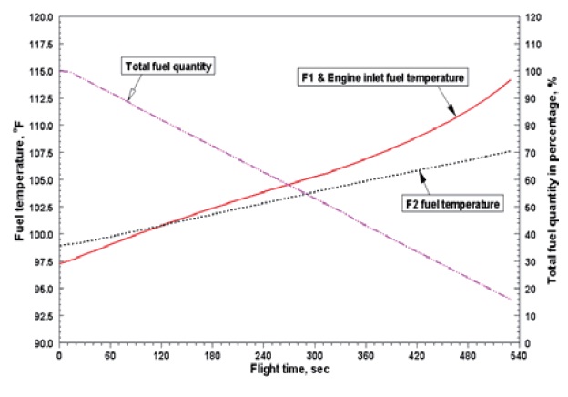
As described above, the UAV flight condition has many different phases with various altitudes and flight speeds. It is assumed that the fuel in F-2 is consumed completely within 9 minutes before using the fuel in the next tank, F-1. The temperatures of the fuel tanks are increase continuously during flight, because of the heat flux from aerodynamic heating and the heat dissipation from the fuel boost pump. From the present analysis, it is found that the trend of fuel temperature in each tank looks very similar. The exception to this is that of the F-1 tank in the later phase. Just before the completion of a flight mission, the fuel temperature of the last tank, F-1, increases more steeply because the fuel in it is almost exhausted. As shown in Fig. 8, the calculated fuel temperature of F-1 is 114 oF, and that of F-2 is 107 oF in 20%-probability hot day conditions. The temperature of the fuel in F-1 is a little higher than that of F-2. This is because the fuel in F-1 is exhausted first, and so the boost pump is installed in it. The initial temperature of fuel in F-2 is higher than that in F-1. In contrast, the temperature of fuel in F-2 becomes higher than that in F-1 after 125 seconds of flight. The temperatures of fuel increases more steeply in the later phases of flight, because the fuel is almost exhausted.
[Table 3.] Initial maximum temperature in fuel tank by solar radiation on the ground
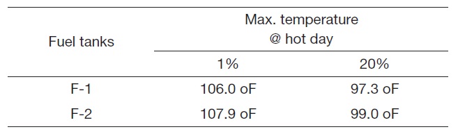
Initial maximum temperature in fuel tank by solar radiation on the ground
Aviation fuel can be used as a heat sink for a flight vehicle. The temperature of fuel in a vehicle’s fuel tank is influenced by many different heat sources, such as solar radiation and heat dissipation from an electric generation system. Therefore, a vehicle’s fuel system should be designed to ensure normal operation of the engine in both non-operating ground static and in flight transient conditions, with respect to temperature requirements. In the present study, a typical model of a UAV’s fuel system is suggested for the prediction of the onboard fuel temperature in flight. The variation in the fuel temperatures caused by solar radiation during ground non-operating conditions is estimated by numerical analysis. The peak fuel temperatures in the tanks are identified as 97.3 oF after 19 hours exposition for F-1 and 99.0 oF after 17 hours exposition for F-2. These results show that solar radiation, the exposed area, and the amount of fuel in the tanks are major factors that influence fuel tank temperatures.
Based on a pre-determined initial fuel temperature, transient analysis of the fuel temperature is carried out by using a finite difference method and its numerical calculation is done by an explicit method. The results show that the fuel temperatures in each tank were increase along with fuel consumption to 114 oF in F-1 and 107 oF in F-2 in 20% probability hot day conditions. The present analysis method may be very useful in predicting the fuel temperatures in the fuel tanks of flight vehicle. This could then be used as basic data for designing the thermal management system of such vehicles. However, the assumptions used for this study need to be more realistic.