Much research on the development of Morphing Aircraft Structures (MASs) has been carried out for the improvement of aerodynamic efficiency, and also for the development of an aircraft which can fly efficiently at various flight conditions for various missions. The types of morphing wings can be classified with regard to two purposes. The first one is to change the wing shape for the operating conditions or to improve mobility. These morphing aircrafts can perform multiple flight missions that are difficult to achieve using a fixed wing shape. Typical examples are a change in the span length [1,2] and a controllable sweep back angle [2,3]. The other one is to maximize the aerodynamic efficiency by substituting the section that causes aerodynamic losses. A controllable winglet [4,5] to minimize the wing tip vortex is an example.
Most of the aircrafts use a conventional mechanical flap. However, these flap systems inevitably contain discontinuous sections that cause aerodynamic losses [6]. Numerous morphing mechanisms have been proposed to suppress the aerodynamic losses by continuously changing the shape of the airfoil. Particularly, Peel et al. [7] developed a morphing wing with a composite skin and pneumatic rubber muscle actuator. James et al. [8] proposed a morphing wing by using a shape memory polymer (SMP) for the wing skin. Bubert et al. [9] developed a passive elastomeric matrix composite skin for a morphing wing. He demonstrated a broad-scale area change while maintaining resistance to aerodynamic loading. Baier and Datashvili [10] introduced several examples of the morphing structures including a morphing wing, skin, and mechanisms. In their review paper, they addressed the technological, design and simulation aspects of current active and morphing aerospace structures. Generally, a morphing wing requires a change in the length of the wing skin and this requires the skin to be flexible. On the other hand, the skin has to possess enough stiffness to resist external aerodynamic pressure. Thus, it is not easy to develop a morphing skin that has contradictory characteristics.
In this research, a new flap morphing mechanism using a smart actuator was proposed to change the wing section smoothly and it does not require a change in the length of the skin. We used shape memory alloy (SMA) wires as actuators for operating the mechanism. SMAs represent a shape memory effect (SME); the shape of SMAs can be changed by changing their temperature. SMA wire has great advantages as a morphing actuator and this is due to its shape memory effect and its simple actuation mechanism. Resistive heating method was used to actuate the SMA wire actuator. Moreover, the allowable current range was experimentally investigated. In order to demonstrate the feasibility of the morphing mechanism, a wing section that has a Clark Y airfoil was fabricated with SMA wire actuator and the actuation test was performed. The aerodynamic characteristics of the morphing
wing was also analyzed by using the commercial programs GAMBIT and FLUENT.
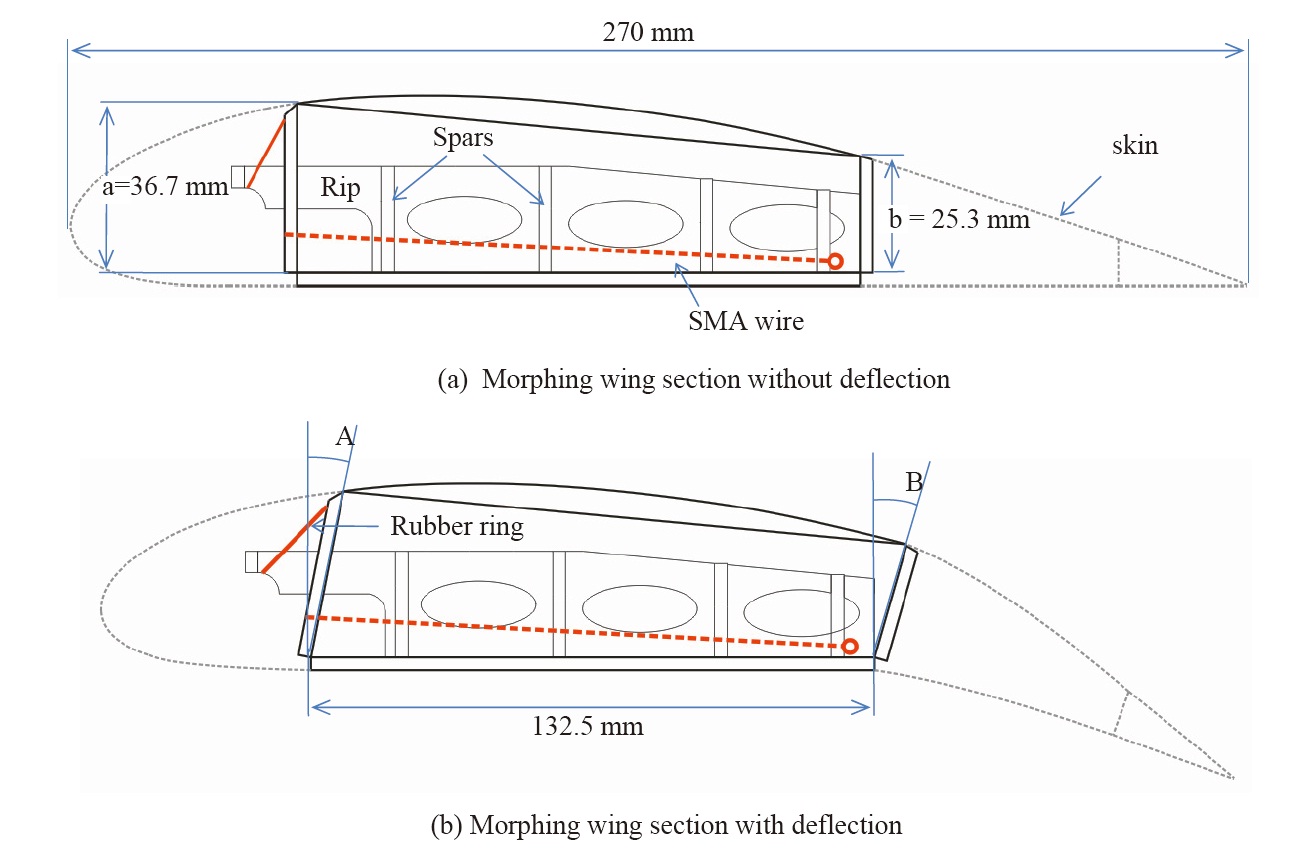
The morphing wing was composed of the wing skin, spar, rib, quadrilateral frame, and SMA wire actuator and it is as shown in Figure 1. The lower part of the quadrilateral frame was fixed with spars and ribs. The upper and lower part of the quadrilateral frame was bonded with the skin. The SMA wire actuator was fixed at the rear lower part of the quadrilateral frame and it was linked with the front part of the frame. Details of the wing frame, skin, and SMA wire installation are shown in Figure 2. When the temperature of the SMA wire increases up to the actuation temperature, the SMA wire shrinks and the quadrilateral frame becomes deformed by the SMA wire actuator. This is shown in Figure 1(b). The upper skin moves backward by the deformation of the frame and the trailing edge shifts downward like a flap. As shown in Figure 1(b), the deflection angle of the trailing edge part directly depends on deflection angle ‘B’. This is due to the skin that is bonded to the frame. Moreover, the length of the skin in the trailing edge does not change. Angle ‘B’ can be controlled and amplified
by angle ‘A’ and the ratio of length ‘a’ to length ‘b’. Angle ‘A’ is controlled by the SMA wire. Generally, SMA wire generates a large force with a small deflection. Therefore, in order to amplify angle ‘A’, it is more appropriate to install the SMA wire in the lower part of the leading edge frame ‘a’. If SMA wire’s temperature decreases less than the actuation temperature then, the force generated by SMA wire decreases and the wing shape recovers to the original shape by the elasticity of the wing.
3. Fabrication of the morphing wing model
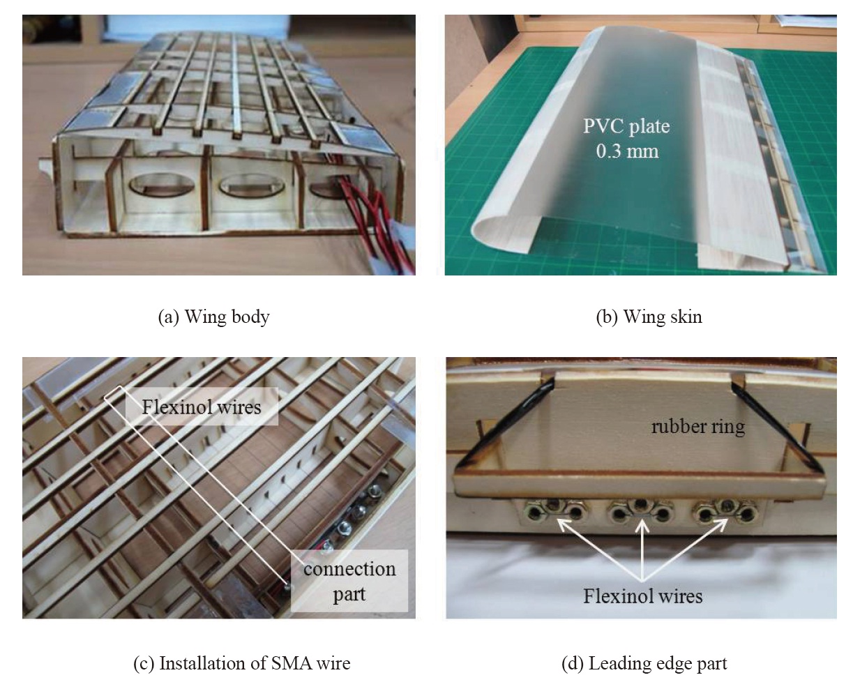
To demonstrate the proposed morphing wing mechanism, a test model was fabricated. A wing section was fabricated and its chord length was 275 mm, and span length was 366 mm. The airfoil shape of the wing was based on Clark Y airfoil. Its maximum thickness was 11.7% of the chord. Clark Y airfoil has a relatively flat lower surface and it is easy to install the quadrilateral moving frame in the wing. The wing frame including the quadrilateral moving frame was made with 3 mm plywood and this is as shown in Figure 2(a). A total of six SMA wire actuators were installed in the wing frame. Each wire was installed in U-shape as shown in Figure 2(c). The ends of each wire were fixed with a bolt and nut in the rear bottom of the moving frame. Figure 2(d) represents the installation of the SMA wires in the front part of the moving frame. The skin of the wing was made with a 0.3 mm poly vinyl chloride (PVC) plate, and balsa was used to reinforce the skin in the leading edge and trailing edge parts.
Flexinol wire supplied by Dynalloy, Inc. was used for the SMA wire actuator. Its diameter was 0.203 mm and its austenite starting (AS) temperature was 90℃. The SMA wire was actuated at a temperature that is higher than the AS
temperature. The temperature of the wire was increased by resistive heating. The joule heating (resistive heating) is very effective for quickly increasing the temperature of the SMA wire, but even a little over-current can induce over-heating of the wire. If the temperature of the SMA wire increased higher than the annealing temperature by the over-current then, the characteristics of the SMA wire as an actuator is changed and degraded. Therefore, we had to make sure that the over-heating of the SMA wire is prevented. The appropriate current range for the Flexinol wire was measured from an experiment: 10 cm of Flexinol wire was used in the test, one end of the Flexinol wire was fixed to a fixing jig and the other end of the wire was fixed to a load cell and the load was measured when an electric current was applied. The wire was nearly fixed and the contraction of the wire at high temperature was negligible. The load increased as the current increased up to 0.7 A. The force generated by the SMA wire was about 25 N and the electric power was 1.47 W. However, the load decreased when the current was larger than 0.8 A. The SMA wire was over-heated and the actuation characteristics were degraded at a current that was larger than 0.7 A. The appropriate current range was smaller than 0.7 A.
4. Actuation test of the morphing wing
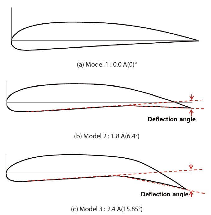
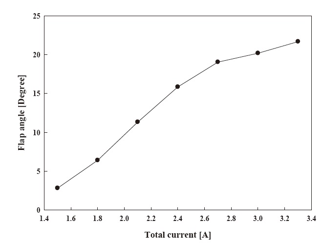
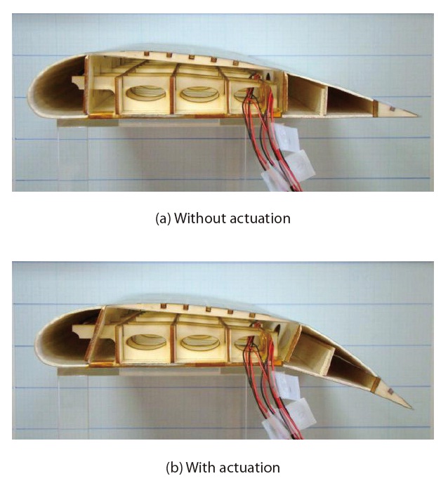
As shown in Figure 3, the actuation test of the morphing wing was performed. Electric current was applied using DC power supply to the six Flexinol wires. The test was performed by increasing the electric current 0.3 A in the electric current range of 1.5 A-3.3 A (0.25A-0.55 A per wire). The deflection angle of the trailing edge was measured for each case. It was measured based on the flat bottom surface which is as shown in Figure 4. The deflection angle was 6.4° and 15.85°
when the current was 1.8 A and 2.4 A, respectively. When the quadrilateral frame was changed by the SMA wire, the skin moved backward continuously. As a result, the shape of the leading edge also changed a little. The deflection angle of the morphing wing in terms of the electric current is presented in Figure 5. The deflection angle increased as the electric current increased. However, the deflection angle change did not increase linearly. The slope of the deflection angle was reduced at a large current level. It appears to be the nonlinear thermo-mechanical characteristic of the SMA wire. It also related to the stiffness change of the wing structure by the shape change. The maximum deflection angle was about 21° at 3.3 A. The maximum possible frequency of the flap motion was around 0.1 Hz.
5. Aerodynamic analysis of the morphing wing
The aerodynamic characteristics were investigated by using the commercial software, GAMBIT/FLUENT. Three airfoil shapes were analyzed: the undeformed airfoil and the two deformed airfoils at 1.8 A and 2.4 A. They are presented in Figure 4. The deflection angles were 0°, 6.4° and 15.8°,
[Table 1.] Comparison of Cl, Cd and Cl/Cd
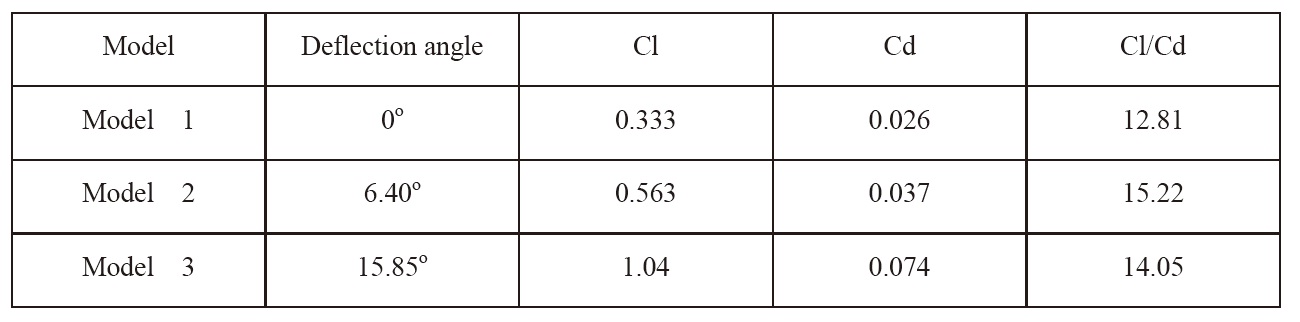
Comparison of Cl, Cd and Cl/Cd
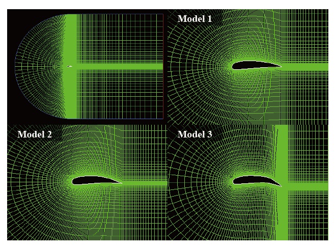
respectively. Aerodynamic analysis was carried out under the following conditions: the flight velocity was 20 m/s at sea level, air density and viscosity was 1.25 kg/m3 and 1.789e- 5 kg/mㆍs, respectively. A k-omega SST model was used for transient analysis with an incompressible condition. Figure 6 shows the grids of each analysis model for the CFD analysis.
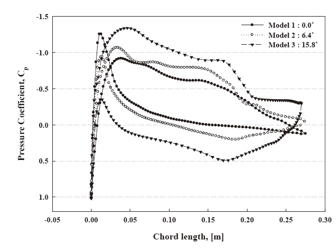
Figure 7 shows the pressure coefficient distributions of the three cases. The pressure difference of the upper surface and the lower surface increased as the deflection angle increased. The pressure coefficient distributions of models 2 and 3 decreased rapidly around a chord length 0.7 c. The slope of the upper surface around 0.7 c rapidly changed and flow separation appeared. The lift coefficient, drag coefficient, and lift to drag ratio coefficient are compared among the three models that are shown in Table 1. The lift coefficient and drag coefficient increased as the deflection angle increased. However, the lift to drag coefficient was the largest for model 2 among the three models.
We proposed a new flap morphing mechanism by using an SMA wire actuator to avoid the aerodynamic losses that are caused by geometric discontinuity. Flexinol wires were used as SMA actuators to operate the morphing wing model. The maximum allowable current for the SMA wire was measured. This was done to prevent the overheating of the SMA actuator. We determined that the Flexinol wire actuator should be used at or below 0.7 A. The deflection angle at the trailing edge increased nonlinearly as the electric current increased but for an electric current range of 1.5 A to 2.7 A nearly linear behavior appeared. The maximum deflection angle was 21° and the maximum possible frequency was about 0.1 Hz. The aerodynamic characteristics were investigated by using the commercial software GAMBIT/FLUENT. The pressure difference of the upper surface and lower surface increased as the deflection angle increased. However, aerodynamic losses occurred due to the flow separation on the section where the shape changed rapidly. If the wing shape changes more smoothly then, the flow separation will be suppressed and the aerodynamic characteristics will be improved. This will be investigated in our future study.