A State matrix
B Control matrix
CD Drag coefficient
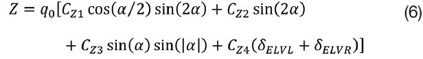
CL1, CL2 Aerodynamic coefficients in roll moment equation
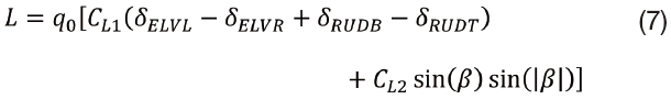
CM1, CM2, CM3, CM4 Aerodynamic coefficients in pitching moment equation
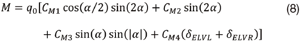
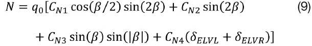
CN1, CN2, CN3, CN4 Aerodynamic coefficients in yaw moment equation
CX1, CX2 Aerodynamic coefficients in axial force equation
CY1, CY2, CY3, CY4 Aerodynamic coefficients in lateral force equation
CZ1, CZ2, CZ3, CZ4 Aerodynamic coefficients in normal force equation
E Identity matrix
Ereq Solar energy required for airship
F Normal force, Fineness ratio
F0 All external forces acting on body
I0 Inertia matrix taken about the origin of the body frame
I'0 Added inertia matrix
k2 ? k1 Added mass factor for ellipsoids
L Roll moment
M Bending moment, pitching moment
m Airship mass
ms Airship structural mass
mp Airship payload mass
M' Added mass matrix
N Yaw moment
p Roll rate
P0 Power required by payload
q, qo Pitch rate, Dynamic pressure
r Yaw rate
rG Position vector

Skew symmetric matrix of the position vector
S Hull cross-sectional area, Total hull surface area
T All external torques acting on body
tday Number of seconds in a day
u Axial velocity, Gust velocity

Average velocity
V, v Airship speed, lateral velocity
Vmax Maximum volume of the airship
vo Linear velocity

Linear velocity derivative
w Normal velocity
X Force in the x-direction (axial force)
x State vector

State space equation
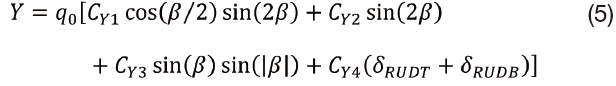
Y Force in the y-direction (lateral force)
Z Force in the z-direction (normal force)
α Angle of attack
β Sideslip angle
δAIL Differential elevator and rudder deflection
δELV Symmetric elevator deflection
δELVL Left elevator deflection
δELVR Right elevator deflection
δRUD Symmetric rudder deflection
δRUDB Bottom rudder deflection
δRUDT Top rudder deflection
η Control vector
ηp Propulsion system efficiency
ρ Air density
ρA0 Air density at sea level
ρHO Lifting gas density at sea level
σp Ratio between air density at design altitude and at sea level
μ Propeller pitch angle
τ Throttle
ω Angular velocity of the body-fixed frame
ω Angular velocity

Angular velocity derivative
An airship is a “lighter-than-air” aircraft which unlike traditional fixed-wing and rotary-wing aircraft uses buoyancy forces as its main source of lift instead of conventional lifting surfaces such as wings and blades. These buoyancy forces are produced by lifting gases contained within the airships envelope which have a density less than that of the atmosphere. The most common types of airships have the classical “teardrop” shape or axi-symmetric design and can be classified as either non-rigid, semi-rigid, or rigid.
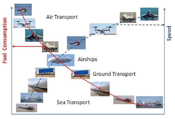
Airships offer advantages over conventional air cargo transport because they do not require any power to stay aloft since all the necessary lift is acquired from the buoyancy of lifting gases. This significantly reduces the power requirements and fuel consumption for transportation and thus reduces the overall operating costs. Compared to ground and sea transportation, airships require greater fuel consumption but have a significantly lower travel time. These advantages and disadvantages are visible in Figure 1 below which places airships in a unique niche in the transportation industry and shows their economic potential.
The history of airships has its beginnings in the eighteenth century with the first recorded flight of a non-rigid dirigible by Jean-Pierre Blanchard it 1784. The airship consisted of a balloon fitted with a hand powered propeller for propulsion. Attempts at adding propulsion to balloons continued into the nineteenth century with Henri Giffard who was the first person to make an engine powered flight. In 1852, he flew 27 kilometers in a steam powered airship. Twenty years later in 1872, Paul Haenlein flew an airship over Vienna that was powered by an internal combustion engine, the first time such an engine was used to power an aircraft.
In the 1890s Count Ferdinand von Zeppelin began experimenting with rigid airships. This led to the launch of the famous Zeppelins and the “Golden Age of Airships”. During the first half of the twentieth century airships gained popularity for passenger transport and military uses such as tactical bombing, reconnaissance, surveillance, and communications.During World War I, Germany, France, Italy, and Britain all used airships for various military operations.The Norge, an Italian semi-rigid airship became the first confirmed aircraft to fly over the North Pole. The USS Shenandoah was the first American built rigid airship. It was operated by the United States Navy and first flew in 1923. The Shenandoah was the first airship to fly across North America and was the first dirigible to use helium as a lifting gas.
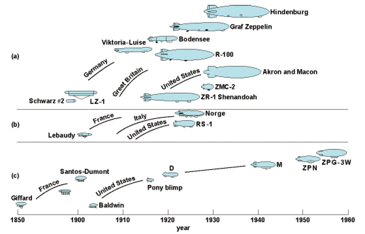
In 1937, moments before landing, the Hindenburg, a hydrogen filled rigid airship burst into flames, killing 36 people onboard and becoming one of the most well-known and widely remembered airship disasters of all time. The public’s confidence in airships was shattered by this disaster. This along with the onset of World War IIbrought the use of airships for passenger transport to a halt.Airships also saw deployment during the Second World War and were predominantly used by the United States Navy for patrol and convoy escorts for ships to detect enemy U-boats.In the years since the war, airships have seen a decline in popularity and usage. In present day, airships are typically used for advertising, sightseeing, surveillance, and research. Figure 2 below shows a timeline of airship development starting in the 1850s with Henri Giffard’s first engine powered dirigible and ending in the 1960s.
A non-rigid airship, more commonly known as a blimp uses higher internal pressure from its lifting gases to maintain both its shape and structural integrity.The word blimp was
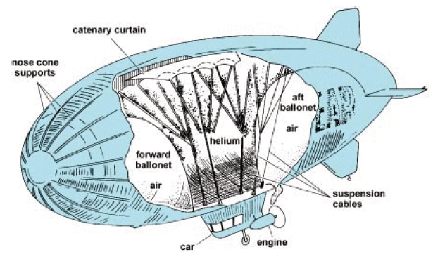
termed by the sound that the envelope of the airship makes when you tap it with your finger [3]. Most often, non-rigid airships use helium as their lifting gas to fill internal ballonets located inside the ship’s outer envelope which provide both balance and the aircrafts external shape. Ballonets are also used to balance volume changes of the lifting gas due to both altitude and temperature change and are also associated with pitch control. This assures that the overpressure of the gas can be maintained and speed and steering ability are not affected. Sometimes instead of using lighter than air gases, these airships will use heated air as their lifting medium. These are termed hot-air airships. The only rigid components of theseconfigurations are the engines, fins, and the gondola or car that hangs from the blimp’s belly [3]. Historically, these aircraft launched “lighter-than-air”, where they received enough buoyancy from their internal gases to lift them off the ground. Modern non-rigid airships however usually lift off overweight so they need to lift their nose and apply propulsive forces or angle the engines downward to achieve takeoff.Non-rigid airships are the most commonly used form of airships today because of their ease of construction and storability. Fig. 3 below shows a typical non-rigid airship with its internal structural layout.
Semi-rigid airships are similar to blimps in that they have no internal frame to support their envelopes. They do have, however, rigid objects on them that give them some backbone. A stiff keel runs along the length of the airship for distributing weight and attaching fins and engines [3]. The keel also provides structural integrity during flight maneuvering. Similar to non-rigid airships, the shape of the hull is maintained largely by an overpressure of the lifting gas. Light framework at the nose and the tail may also contribute to the hull’s outer shape. For small types the lifting gas is
sometimes held in the hull itself, while larger types tend to use separate gas cells, which mitigates the consequences of a single gas cell failure and helps reduce the amount of overpressure needed [4].Semi-rigid airships fell out of favor for many years after the 1930s until the development of the Zeppelin NTs which are some of the more recent and popular semi-rigids in use today.
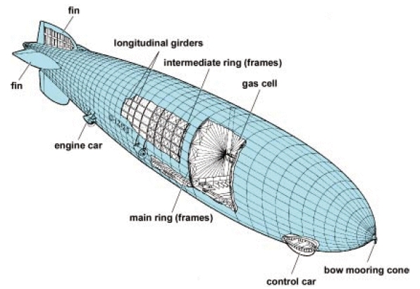
Unlike non-rigid and semi-rigid airships that maintain their shape by the internal pressure of lifting gases, rigid airships retain their shape from an internal structural framework on which the aircraft’s outer envelope is connected. With the internal framework, a rigid airship has the capability of being built much larger than a non-rigid or semi-rigid dirigible because there is no chance of kinking in the hull due to aerodynamic forces and moments. Inside the internal framework, the airship is filled with multiple gas cells holding the lifting gases. Because of the size of most rigid airships, using multiple gas cells minimizes the chances of a catastrophe in
the event that one is compromised. A typical rigid airship with its internal structural layout is visible in Fig. 4.
3.1. Heavy Lift Vehicles (HLVs)
A number of Heavy Lift Vehicle (HLV) concepts have been proposed for cargo and passenger transportthat are efficient and cost effective. These vehicles have excellent fuel economy, which make them viable alternatives to conventional transportation methods over short distances. A number of feasibility and comparative studies by the National Aeronautics and Space Administration (NASA) and others [5-12] have been performed confirming the effectiveness of airship lifting platforms for transport. Capable of transporting payloads ranging from 1 to 1,000 tons these heavy lift airships have enormous economically potential. Typical operating altitudes for such vehicles areusually less than 15,000 feetat low flight speeds between about 80mph and 120 mph.
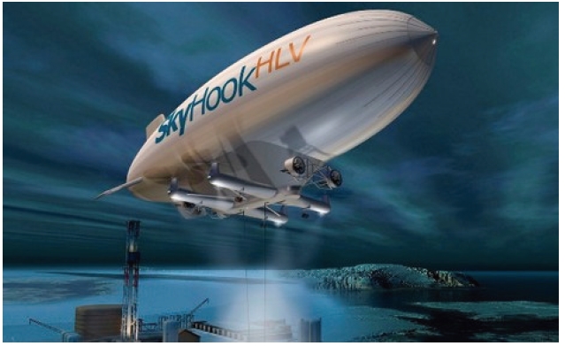
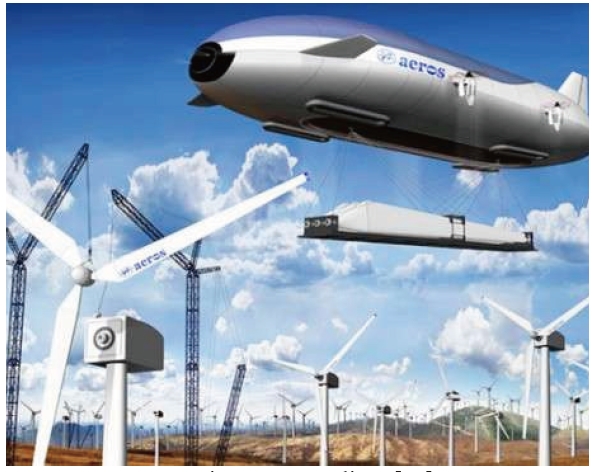
Many projects and endeavors involving the development of these heavy lift airships have been proposed in recent years. One undertaking worth taking note of is DARPA’s Walrus HULA (Hybrid Ultra Large Aircraft) program. The Walrus program aimed to develop and evaluate a very large airlift vehicle concept designed to control lift in all stages of air or ground operations including the ability to off-load payload without taking on-board ballast other than surrounding air. The Walrus operational vehicle was intended to carry a payload of 500-1,000 tons up to 12,000 nautical miles, in less than 7 days and at a competitive cost [13].Some examples of other heavy lift vehicle concepts can be seen below. The SkyHook JHL-40 seen in Fig. 5 is a joint project between SkyHook and Boeing which will be capable of carrying 40 tons. It will be 302 feet in length and use four helicopter rotors to lift its payload and propel itself, making it the largest helicopter in the world [14]. TheAeros Pelican is
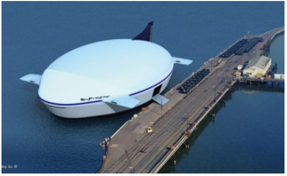
shown in Fig. 6 which is a proposed 60 ton payload vehicle. The SkyFreighter from Millennium Airships can be seen in Fig. 7, aconcept proposed for both commercial and military applications.Additional concepts can be viewed in a review of heavy lift systems by Ardema [15].
3.2. High Altitude Airships (HAAs)
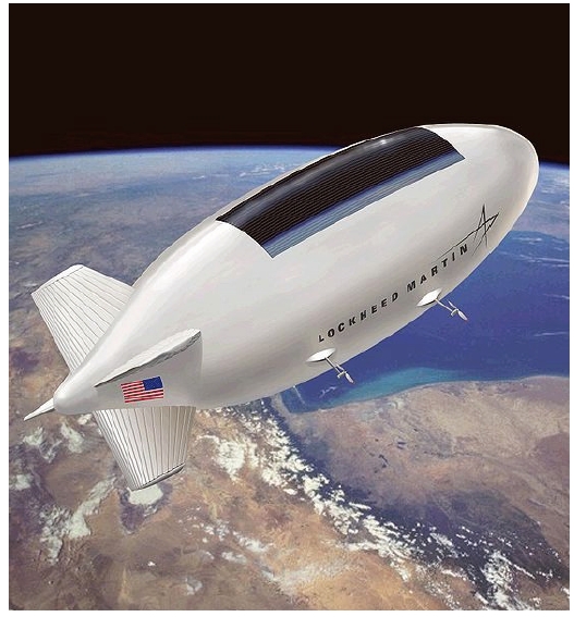
Many concepts for High Altitude Airships (HAA) have also been proposed for intelligence gathering, surveillance and reconnaissance, and communications which will offer cheaper alternatives to satellites. Fig. 8 below shows a HAA concept under development by Lockheed Martin which would operate at altitudes of about 60,000 ft. In recent years the topic of high altitude and stratospheric airships has become very popular and received much attention. A great deal of work has been put into this subject for the modeling and analysis of these airships [19-23]. Most of these airships are remote operated aircraft or unmanned aerial vehicles because of their high operating altitudes. The U.S. Army Space and Missile Defense Command developed the
HiSentinel stratospheric airship program to design a family of high altitude, long endurance airships for unmanned military operations. These airships, such as the HiSentinel 80 operate with the use of solar power at altitudes ranging from 13-15 miles above the Earth [24].
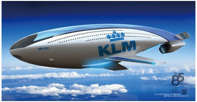
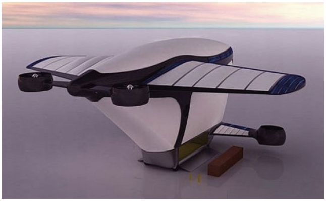
Hybrid airships are aircraft that combine lighter than air technology of aerostats and heavier-than-air technology of traditional fixed-wing or rotary-wing aircraft.Hybrid aircraft can offer many advantages over traditional airship configurations. For example, adding a pair of wings to the main vehicle body helps to produce substantial aerodynamic lift, improve vehicle stability, decrease drag, as well as increase payload capability [26]. Two examplesof winged airship concepts can be seen below; the WB-1010 (Fig. 9) and the Airship One (Fig. 10).No hybrid airship has been built for production but several manned and unmanned experimental vehicles have been flown demonstrating the technology.
3.4. Unconventional Body Shapes
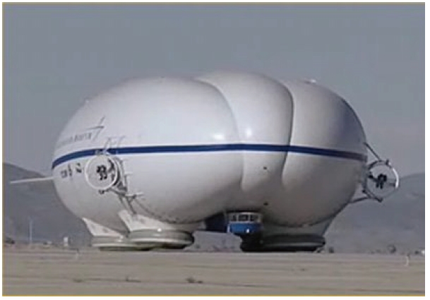
A number of designs that display geometries that stray from the conventional double ellipsoid, axisymmetric hull shape have been proposed in recent years. For instance, the P-791 seen in Fig. 11 is an experimental hybrid airship that exhibits a triple hull design. Developed by Lockheed Martin and first flown in 2006, this design maximizes the hull volume and lifting gas capacity to maximize lifting capability. Similar designs have been proposed butt with a double hull. Another hull trait that is new to airship design is the use of an airfoil shaped cross sectional area along the longitudinal axis to produce dynamic lift. In effect, this makes the hull itself a lifting surface similar to a wing.
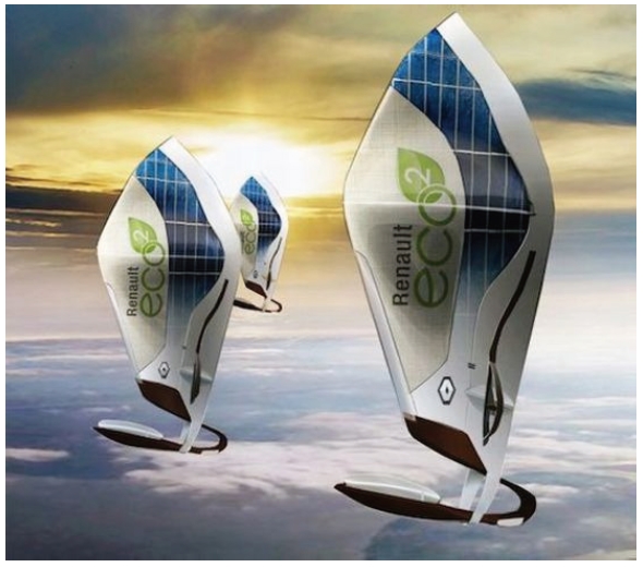
The Renault Zep’lin in Fig. 12 is a more radical concept
with an unconventional shape. Its unique hull design not only acts as a storage vessel for lifting gases to provide aerostatic lift but as a sail for additional lift, propulsion, and directional control.
4. Airship Design and Optimization
Some of the earlier scientific and technical documents related to airship design can be found as technical reports from NACA and the Royal Aeronautical Society (RAeS). One of the most famous is a report by Lamb [31] focusingon the study of inertia coefficients of an ellipsoid moving in a fluid: these coefficients were needed to keep into account added masses in airship design. The increased interest in airships of the first years of the 20th century was supported by studies on airship design focusing their attention on aerodynamics and weight which was considered at the moment the two most critical issues in the design of airships. Two reports by Tuckerman, the first dealing with the determination of forces on an airship hull [32], and the second focusing on inertia factors [33] show the need for a precise loads assessment in order to design a lightweight structure able to sustain the stresses due to lifting gas and dynamic pressure. The experience and knowledgein airships gained during the period 1900-1927 by pioneering designers like General Umberto Nobile in Italy, Count Zeppelin and NikolausBasenach in Germany, and Goodyear in the USA are reported in a book by Thomas Blakemore and Watters Pagon [34] where all the subsystems of an airship are considered one by one. The approach followed in [34] to solve the weight estimation (which can be considered the most critical in airship design) is based upon comparison with already designed and built airships where a wide list of tables in which the characteristics ofa large number of airships are listed. In the same year a book by Charles P. Burgess [35]
was edited, in which the approach to size estimation is different: this author proposes a design methodology based on preliminary design calculations, evaluation of static and dynamic bending moments, gas pressure stresses, design of cars for power systems, passengers, and flight crew, gas cells, and finally tail cones, stabilizing surfaces, and mast mooring gears. This book provides one of the first examples of a complete list of formulas to be used for the initial estimation of size and horsepower for a given performance and proposes a well coded “step by step” embodiment process to deploy the entire design process in a systematic way.
A resume of the design experiences of the years up to the 1940s can be found in a technical manual [36] in which the formulas and methodologies developed for the design are summarized in a very practical and “design oriented” way. The Hindenburg accident and the interest towards vehicles with higher speed deadened the interest in airships, and in 1962, the US Navy program for airshipsstoped. The design process of airships is kept going by Kostantinov [37] who collected the formulas and experiences in the field of airships and merged the up to date aerodynamic and structural research in a comprehensive paper. Since the 1970s, airships and blimps are designed for advertising purposes or touristic adventure trips: Goodyear in USA and Zeppelin in Germany are good examples of such activities. The increasein personal computers and the computational load available made possible the solutions of complex equations and the large number of simulations that can be ran simultaneously, compared to experimental data (as for the studies of CFD related to the German LOTTE). Also the airship design field was affected by these new capabilities: the work of Lutz et al. [38] is one of the fist describing the optimization of the shape of an airship by means of evolutionary algorithms
and stochastic methods: the airship design process can make now use of the new available computing capabilities. Khoury and Gillet [39] present a book in which a chapter is devoted to Design Synthesis. Airship design now focusesits attention on the integration of sub-systems and trade-off considerations. Moreover, the design process is divided in Conceptual, Preliminary and Detailed phases. Flowcharts are presented to drive and support the designer in the Conceptual Design phase, in the trade off analysis, and in the trade study process. The airship is considered as a system, and the mutual interactions between subsystems (condensed in the airship sizing matrix) is considered the key of success for a good and balanced design. Also, sensitivity analysis and parametric weight estimation (derived from the aircraft conceptual methodologies [40]) are introduced in this comprehensive book.In the end of the 20th century, flight simulation is proposed not only for the training of pilots [41], but also to check the design results and to verify the behavior of the airship,even inthe conceptual design phase. The availability of new film materials, efficient solar panels, and the need for high altitude observation platforms focused the attention of designers to High Altitude Platforms (HAP). In a study by Mueller et al. [42] the design of a HAP is presented in a parametric way: data like weight of the envelope and efficiency of solar panels are not kept fixed. The design process output is not a defined sizing, but a series of graphs which the designer can use to dimension the airship with materials available at the moment. With this method, the design can be updated if new materials or technology become available. The basic formula used to evaluate the volume of the airship [42] is:
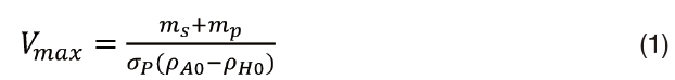
where Vmax is the maximum volume of the airship,
Also, in the work of Wei et al. [43]andNickol et al.[44] the attention is focused on the trade-off analysis, on the sensitivity analysis, and on how the airship would be impactedby a new technology or change in mission requirement. In the latter of these two papers, the design is based upon the proposal of several configurations, each one evaluated in the mission through a Life Cycle Cost Analysis approach where a design is considered good if it presents a cheap operational cost and a low cost for environmental impact and final dismissing. The work of Yu and Lu [45] presents a flowchart describing the design process for a HAP; moreover, a list of tables shows how the change of design parameters (like the purity of helium, or the sunlight hour related to the season of the year) affect the lift. The most interesting part of this study reports the effects of technology advances on airship performance parameters: by this way the designer can have an idea of how the payload can be increased with an increase in propeller weight/massratio and solar cells efficiency, or a decrease of envelope area weight and batteries capacity/mass ratio. Also, Chen [46] presents a similar work of sensitivity analysis arriving at similar results in terms of influence of weights and efficiency on the design: a design flowchart is presented here also to assure the equilibrium between lift and weight due to solar panels, structure, batteries, and propulsion systems. The multidisciplinary approach to design, which is a consequence of a concurrent engineering approach, has been applied also to airship design: the work of Ram and Pant [47] presents the aerodynamic and structural optimization of an airship using variable thickness fabrics and a low drag shape.
As the new reprint of the book Airship Technology [48] reports, in addition to the classical interest related to materials [49], solar panels, and unconventional configurations, one of the challenges for the future is the design of multi gas, multi chamber airships [50] seems to be a solution for cost reduction and lower environmental impact.
5.1. Structural Design and Analysis
Structural analysis in an important area in airship design because airships experience deformation under aerodynamic and aerostatic loads. Predictions of loads, stress distribution, and bending moments are useful in both the design of airships and the preventions of catastrophic failures. Structures technology is discussed in several review works by Burgess et al. [51], Hess [52], and Liao et al. [53] along with structural problems in the construction of lighter-than-air vehicles. The structural properties of the Navy’s rigid airship USS Los Angeles were summarized in a work by Althoff [54]. Burgess also wrote a significant report for the Navy analyzing forces on an airship in wind gusts [55].
Structural strength was a significant issue in the development of early rigid airships. For example, Evans [56] computed the force distribution due to aerostatic, aerodynamic, and inertial forces for the Shenandoah rigid airship and demonstrated the possibility of catastrophic failure due to the structural bending moment [57].For rigid airships several equations for calculating maximum design moment on the hull and methods for distributing design moment over the length of the hull were developed in [58, 59]. One such equation from Goodyear [58] shows:
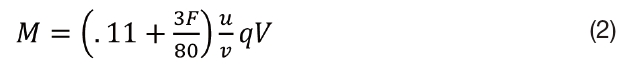
where is the fineness ratio, is the gust velocity, is the airship speed, is the dynamic pressure, and is the airship volume.
Li et al. [60] developed a linear model for flexible airships which was used to study structural flexibility effects on airship flight dynamics and aerodynamics [53]. In this model, the equations of motion of an elastic airship are derived by the Lagrangian formulation and the airship is modeled as a free-free Euler-Bernoulli beam where the bending deformations are represented by shape functions chosen as the free-free normal modes [60].
Recent advances in computational tools such as Finite Element Analysis (FEA) software has allowed for extensive structural analysis to be performed on airships with a high degree of accuracy. Hunt [61, 62] performed static structural analysis of an aerostat with the use of NASTRAN to come up with an idealized structural model by analyzing stress distribution and shape deformation. Similarly in Smith [63], Boeing used the FEA package ABAQUS to develop an internal loads model for the Skyhook HLV aircraft seen in Fig. 5.Bessert and Frederich [64] presented a method to investigate the nonlinear aeroelastic behavior of an airship due to geometric and material nonlinearities. They tested their method on the CL-160 airship using ABAQUS and VSAERO (an aerodynamic solver based on the aerodynamic panel method using potential flow theory) and found that it could handle all the nonlinearities present in the different models, and could deliver the required derivatives which would be difficult to obtain from free-flight or wind tunnel experiments [64].
Materials have made a huge leap forward in the development of airships, making them lighter, stronger, and more efficient.There are very particular demands on materials when it comes to airships construction. They need to exhibit proper properties of strength, weight, air-tightness, weather and UV stability, conductivity, and non-flammability. However, different requirements including performance, cost, risk, and service life have to be considered. Therefore the material becomes a delicate balance between often competing demands such as highest tensile strength vs. lowest possible mass, maximum tear strength vs. maximum adhesion, maximum material life vs. ease of field repair, and minimum price vs. all other demands [65].
In present day, the internal framework in semi-rigid and rigid airshipsis typically made of aircraft-grade aluminum that is riveted. The nose cone is usually made of wood, plastic, or metal and is then laced to the airship’s envelope. The gondola is commonly manufactured with metal [66]. As seen in the rest of the aviation industry new composite materials and carbon fibers are also making their way into the construction of airships as building materials mainly for the use of gondolas and crew cabins.
One of the major design challenges for airships is the use of materials for the construction of ballonets or airbags and envelopes to prevent leakage of the lifting gases but provide flexibility.So airship envelopes are normally made from Dacron and Mylar or other polyester fabric materials. They are sometimes made of Tedlar, a polyvinyl film, which is bonded with Hytrel, a thermoplastic polyester elastomer which provides the flexibility of rubber and the strength of plastic. These fabrics help protect the envelope from ultraviolet light. The ballonets are normally made from leak-resistant polyurethane plastic [66].In a paper by Miller and Mandel [65], the design requirements of airship envelopes and materials and material development and qualification information is examined.
Kang et al. [67] studied the material characterization of a film-fabric laminate developed for a stratospheric airship envelope consisting of a single plain woven fabric layer impregnated in a polymer matrix laminated with thin films. They performed uni-axial tests to obtain tensile properties and finite element analyses to obtain effective tensile properties. McDaniels et al. [68] of the Cubic Tech Corporation examined the use and development of non-woven flexible laminates for lighter-than-air vehicles. They concluded that the use of these flexible laminates achieved a significant weightsavings over woven fabrics of similar strengths by eliminating strength and modulus loss andother structural deficiencies caused by crimping of yarns during the weaving process. Theabsence of crimp in non-woven fabrics results in a linear elastic response that allows for easein predicting material properties and simplification of structural models [69].
Two other important material manufacturers for envelope construction worth taking note of are ILC Dover and Contitech. ILC Dover is the world’s largest producer of modern airship envelopes and has been producing materials for the construction of aerostats since the 1970s. They have served in the production of materials for customers such as the American Blimp Corporation, Lockheed Martin, and Skyhook. Contitech is one of the globe’s leading specialists in rubber and plastics technologyand through innovative manufacturing processes and extremely rigorous finishing quality have developed materials for the special applications of airships.
In terms of today’s airships, helium is by far the predominately used source for lifting gases. Unlike hydrogen, helium is an inert gas so it is not flammable. This is the main reason hydrogen isn’t commonly used today, being responsible for many disasters of early airships such as the Hindenburg. However, with the use of helium comes many tradeoffs which are explored by Gordon et al. [69], Ghanmi et al. [70], andLinner [71]. For example, helium is expensive and supplies are limited whereas hydrogen is both inexpensive and can be easily generated. Helium is also less buoyant than hydrogen and has about 7% less lifting capability [71]. Another trade-off that is not so technically obvious in buoyancy compensation. When an airship takes off with neutral buoyancy the aerostatic lift produced by the helium is equal to the total weight of the vehicle. As fuel is burned en route, however, the total weight of the airship decreases but the aerostatic lift remains the same. If nothing is done,
[Table 1.] Summary of Construction Materials for Recent Airship Projects
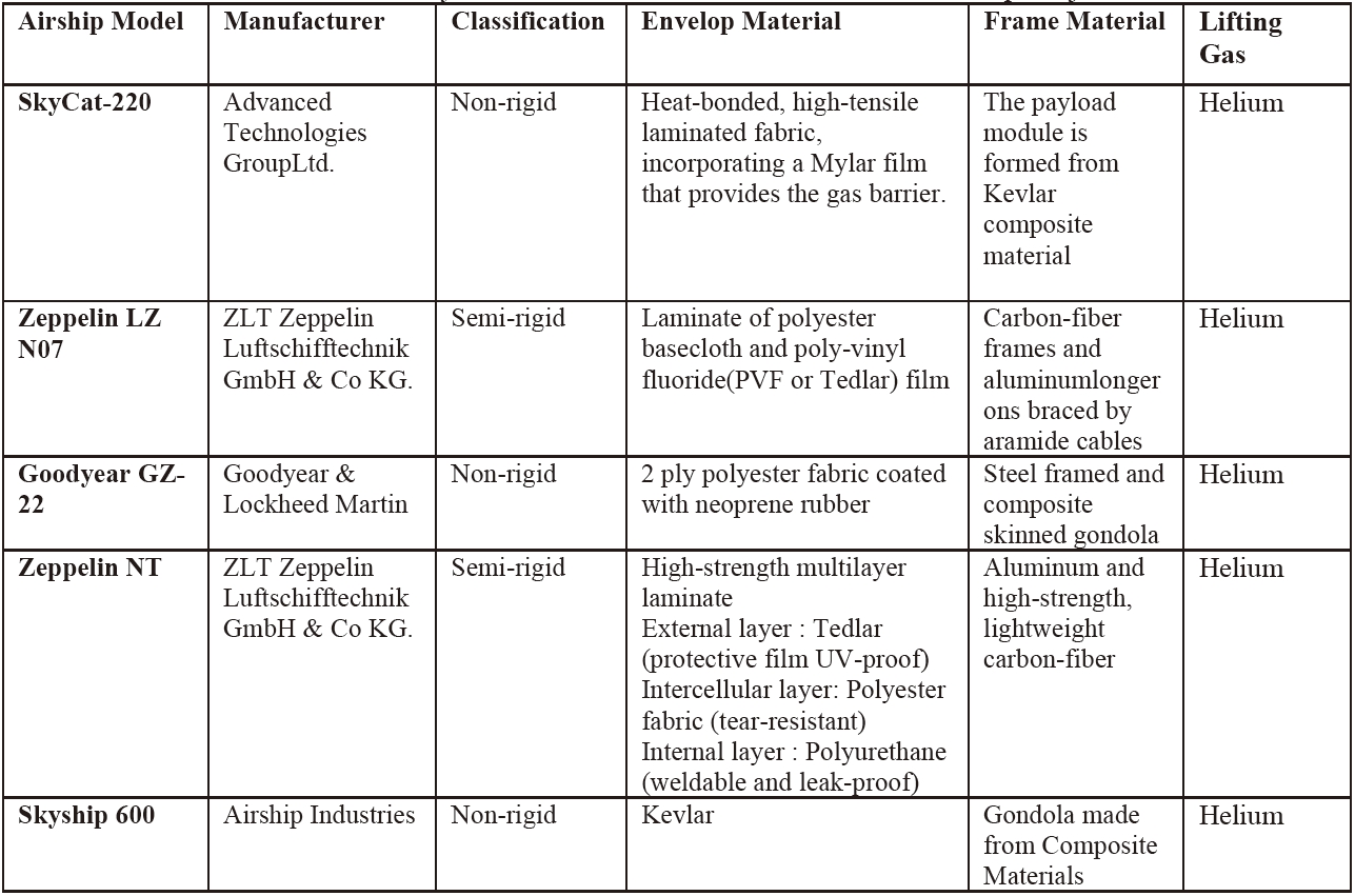
Summary of Construction Materials for Recent Airship Projects
over time the ship will gain significant positive buoyancy [69]. As this is undesirable from both a control and structural viewpoint, the airship must have a mechanism for buoyancy compensation. Hydrogen-filled airships can simply vent excess hydrogen into the atmosphere to compensate for the weight of fuel burned. Since helium is more expensive, helium-filled airships are constructed with an apparatus on the engine exhaust to condense and recover the water it contains. The water is then stored to compensate for the weight of fuel burned [70]. These water condensers can be heavy and provide additional drag being mounted on the skin of the airship.
6.1. Wind Tunnel and Flight Tests
Few publications are available concerning the modeling of airship aerodynamics. A large amount of the available literaturedeals with empirical data and resultswithout addressing or going into too much depth about modeling techniques. Literature that is available for viewing on the aerodynamics of airships mainly deals with the classicaxi-symmetric elliptical bodies of revolution and little is available for unconventional body shapes.
With the lack in development of aerodynamic models for airships in the early years, flight behaviors were mainly analyzed usingflight test and wind tunnel testing. A large wealth of information was collected for wind tunnel test in the 1920s and 1930s for scaled airship models. Jones et al. [72-74]at the Aeronautical Research Committee (ARC) in Britain performed tests on models of theBritish airships R-29 and R-101and the rigid German airship L33. The National Advisory Committee for Aeronautics (NACA) in the United States published multiple reports on wind tunnel testing of the airship Akron [75-79] where experimental measurements were taken of the flow in the boundary layer, pressure distribution on the hull, and ground handling forces. Zahm [80] also presented a NACA report on the air forces, moments, and damping on a model for the airship Shenandoah.
Pannell et al. [81-83] published multiple reports at ARC around 1920 regarding the results of flight tests for the British airships R-26, R-29, and R-33. Testson these airships were performed to determine turn radius at various rudder deflections and the drag forces. However, accuracy of these measurements was poor due to the limited technology of the time. Modern flight test have proven more accurate results and measurements with more advanced instrumentation as seen in [84, 85], where flight tests were performed on the Skyship-500 airship in the Patrol Airship Concept Evaluation (PACE) program measuring the responses to inputs of elevator, rudder, and throttle.
Some of the earliest works for analytical airship aerodynamics models date back to the 1920s and are based on potential flow theory such as the work performed by Monk [86] used for the investigation of the Navy’s ZR-1. In his work, Monk derived the normal aerodynamic force distribution over an airship hull modeled as an elongated surface of revolution using a slender body assumption:
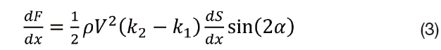
where is the cross sectional area of the hull, is the velocity, is the angle of attack, and is the added mass factor for ellipsoids derived in work performed by Lamb [31] which correct the effects of the hull’s finite length. Monk further concluded that an airship has an unstable pitching moment about non-zero angles of attack.
Potential flow theory offered some basis for aerodynamic predictions but neglected effects of viscosity on the hull, particularly near the aft section of the body where viscous effects become more important. In Allen and Perkins [87], a term related to the cross flow drag was added to Monk’s results to correct for the effects of viscosity and additionally accounted for axial forces.Similar to Allen and Perkins, Hopkins [88] proposed a method in which the transverse forces on the forward portion of the hull could be calculated from potential flow theory and the transverse forces on the remaining portion of the hull could be calculated by relating the local transverse force for the body to the cross flow drag.
6.3. Semi-Empirical Approaches
Jones and DeLaurier [89] further developed this model by accounting for interference between the hull and fins with a semi-empirical approach, defining hull-fin interference factors with experimental data in the analytical model. In their steady state model, the airship is separated into two aerodynamic regions, where the forces and moment on the airship hull are evaluated from the nose of the hull to the point where the hull and fins intersect each other, and where the hull and fins are evaluated together after this intersection point.
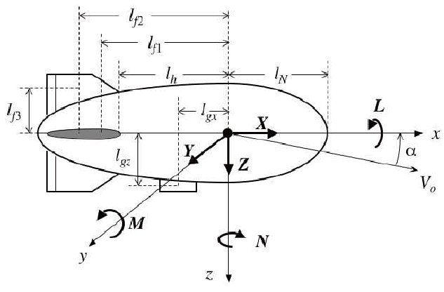
The aerodynamic model below was developed by Mueller et al. [42] following the procedures outlined by Jones and DeLaurier [89] for an axisymmetric airship hull with four equally sized fins which also incorporates the effects of rudder and elevator deflection. The equations for the aerodynamic forces and moments can be seen below where a complete list of the aerodynamic coefficients shown in the equations can be found in [42]. A schematic of this steady state aerodynamic model can be viewed in Fig. 13.

6.4. Shape and Drag Optimization
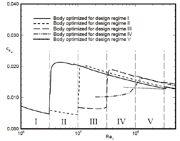
More recent developments in airship aerodynamics have been the use of shape optimization in airship hulls to reduce drag and increase performance. Since power requirements are directly related to drag, optimization is a powerful tool for maximizing an airship’s potential and minimizing fuel consumption. Extensive research has been performed by Lutz and Wagner [90, 91] in developing a method for numerical shape optimization of axisymmetric bodies in incompressible flow at zero incidence.Specific aerodynamic optimizations of bodies of revolution for prescribed Reynolds number regimes were performed. This resulted in minimized drag at maximized volume for Reynolds number regimes relevant for airship application [90]. Fig. 14 shows their resulting minimized drag curves for the optimized body shapes in each design regime.
A similar paper was proposed by Nejati and Matsuuchi [92] using genetic algorithms for shape optimization which showed that the method of using genetic algorithms for optimization could minimize the drag coefficient faster for different Reynolds number regimes.
Computational Fluid Dynamics software tools have allowed researchers to examine the flow interactions with airship bodies to a certain degree of accuracy without the need for expensive wind tunnel testing or full scale flight test saving a great deal of time and money. Such commercial programs like Fluent, Star-CCM+, and FLOW-3D have made these capabilities widely available.
El Omari et al. [93] published an important paper on the challenges of turbulence modeling in airship CFD studies where they investigated three turbulence models based on statistical and Large Eddy Simulation (LES) approaches;a standard high Reynolds k?ε model, a Smagorinsky LES
model, and a variationalmultiscale LES model. Their results showed that all three models predicted the primary longitudinal vortex shed from an airship body but that only thevariationalmultiscale LES model predicted the secondary vertical flow structure observed in experimental studies. In a paper by Wang et al. [94], Fluent was used to accurately simulate the motion of stratospheric airships with a model that calculated the aerodynamics of an airship based on a panel method and an engineering estimation approach.
7.1. Equations of Motion (6 DOF)
An airship is most commonly modeled as a rigid body with six degrees of freedom, three translational and three rotational which results in six nonlinear equations that represent the motion of the airship. The equations can be seen in matrix form below:
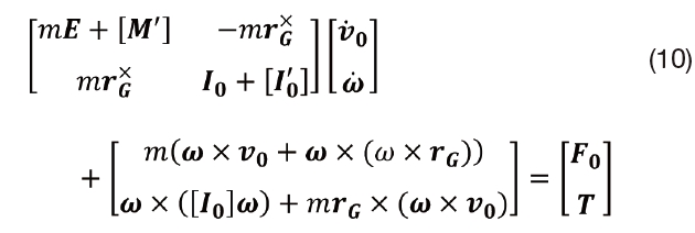
where is the total mass of the system, is the skew symmetric matrix of the position vector, is a 3x3 identity matrix, is the inertia matrix taken about the origin of the body frame, is the added mass matrix, and is the added inertia matrix.The right hand side consists of all the external forces and torques acting on the body. These are made up by the weight, buoyancy force, aerodynamic forces and moments, and propulsive forces. The added mass and inertia matrices are functions of
the vehicle shape [42].
The equations of motion (9) can be linearized and naturally decoupled into two separate modes consisting of the longitudinal and lateral systems. To linearize the equations of motion trim conditions are computed for equilibrium flight and the velocity components of the linear models are treated as perturbations about the trimvelocity. The linearized models can be represented below in state space form:

whereand are the state and control matrices and and are the state and control vectors. The longitudinal state vector consists of the pitch rate , axial velocity , and normal velocity . These states are affected by the control vector consisting of throttle , propeller pitch angle , and symmetric elevator deflection . The lateral state vector consists of the roll rate , yaw rate , and lateral velocity . These states are affected by the control vector consisting of symmetric rudder deflection , and differential elevator and rudder deflection [42]. A complete and detailed derivation of the linearized equations of motion can be viewed in [95].
Although most of the airship lift is generated by the aerostatic forces, the aerodynamic characteristics determine the stability of the aircraft [57]. As seen previously, Monk determined that the body of an airship experiences an unstable pitching moment due to the added mass terms. This also cause the yaw rotations to destabilize, but the viscous effects acting on the aft end of the ship including the tail fins tend to be stabilizing along with other aerodynamic forces normal to the centerline of the airship.In a stability analysis performed by Cook et al. [96], it was determined that the longitudinal modes of the airship are comprised of the surge mode caused by axial aerodynamic drag, the heave-pitch subsidence mode cause by normal aerodynamic drag, and the oscillatory pitch-incidence mode which is caused by the center of gravity being located under the center of volume. The lateral-directional modes of the airship are comprised of the sideslip subsidence mode, the yaw subsidence mode and the oscillatory roll pendulum mode. Approximate models for these modes are derived and expressed in terms of concise aerodynamic stability derivatives in [96].
Kornienko [97] conducted aninvestigationof the stability and controllability of an airship under different flightand configuration conditions with a linearized flight model. The basic dynamical characteristics of the research airship Lotte were determined from the flight data gathered. Similarly, Yamaski and Goto [98] conducted a series of flight tests on a full scale blimp with feedback systems for stabilizing yawing and pitching motions, and a sensor system to measure the motion and control outputs. Data from the tests were analyzed to yield parameter values including added mass effects and stability derivatives. A comparison was made between the experimental values and estimated values obtained using analytical formulas where they were determined to be consistent.
Mueller et al. [42, 99] developed a comprehensive set of modeling, analysis and control designtools for airships at Princeton Satellite Systems Inc. with the help of the Missile Defense Agency. An integrated guidance and control system was designed for a high altitude airship where a simple control law design provided robust feedback control of the airship’s angular rates and velocity.
Recent advances and growing interest in solar power technology indicates that solar energy systems will play a greater role in energy production for airships of the future. In a paper by Lubkowski et al. [100], an analysis is performed of several different solar power technologies to evaluate the trade-offs of the cost against the power consumption, efficiency, and reliability. These technologies included photovoltaic flat panels, thin film photovoltaic panels, trough solar concentrators, stirling dish solar concentrators, and luminescent solar concentrators. Their results show that flat solar technologies such as thin film, luminescent solar concentrators, and photovoltaic flat panels ranked highest. Gawale and Pant [101] present a methodology of determining the initial sizing of a stratospheric airship including the required volume and dimensions based on parameters such as operating altitude, speed, payload, available irradiance, solar cell efficiency, atmospheric conditions, and propulsion system efficiency.
The solar energy required by an airship with an elliptic axisymmetric shape can be computed as
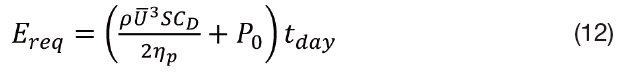
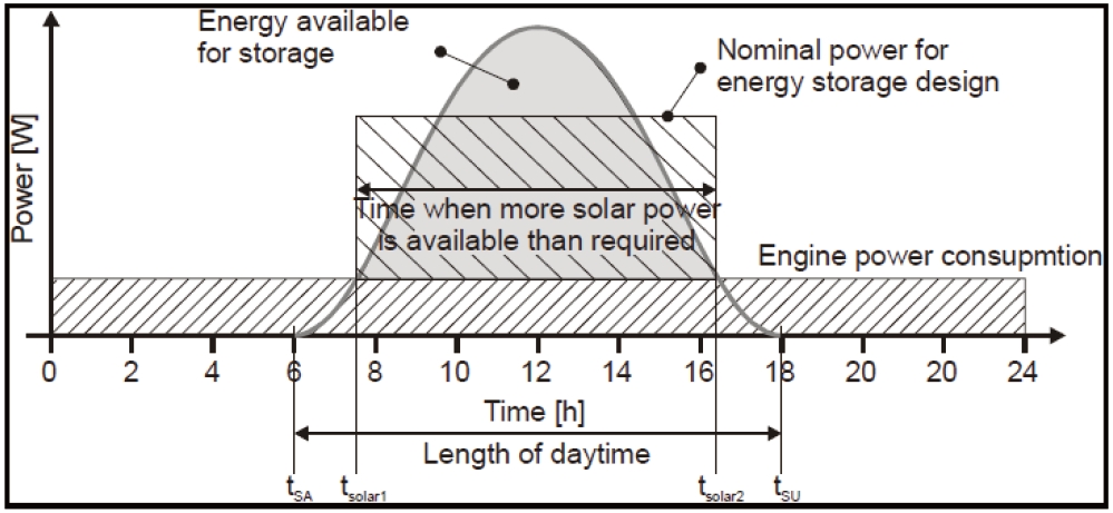
where, is the average velocity, is the total surface area of the hull, is the drag coefficient, is the propulsion system efficiency, is the number of seconds in a day, and represents the power required by the payload [42].This shows that required energy is directly related to parameters such as the size of the airship and mass of the payload. Solar power generation technologies do present some trade-offs. For adequate power generation, solar cells need to cover a substantial amount of the hull’s surface, significantly increasing the weight of the vehicle and contributing to the hull’s skin friction, increasing the overall drag coefficient. Also, solar energy is only available during the daytime which requires additional systems for energy storage for power supply during the nighttime hours. However, solar energy is renewable and can be harvested during flight eliminating the need to carry fuel on board and thus landing to refuel, extending flight operations. The diagram below shows a typical comparison between the solar energy available during the day and the energy required for engine power consumption demonstrating the need for efficient and high capacity energy storage systems.
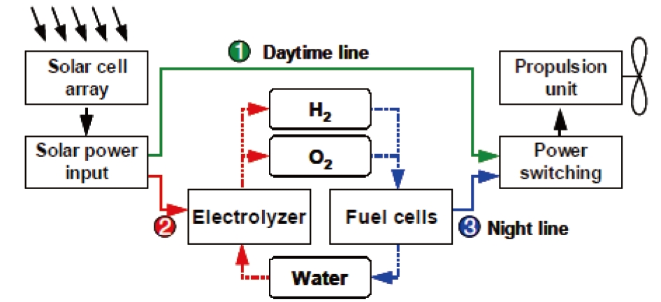
Fuel cells offer a feasible and practical solution to this problem. Fujihara and Eguchi[102] present a report in which a Regenerative Fuel Cell (RFC) is built and tested for airship nighttime operations. The RFC testbed consists of a solar cell
array that generates power from solar energy and transmits it to electrolyte cells for hydrogen and oxygen production. The fuel cell would then use the hydrogen and oxygen to generate power for propulsion. This cycle can be seen below in Fig. 16. Their test results show that the RFC was found to meet design performance requirements.Mitlitsky et al. [104] also explore the use of RFC systems for high altitude long endurance missions.
Colozza and Dolce [103] at NASA’s Glenn Research Center studied the technologies needed to build renewable electrical power systems for long duration observation aircraft, including photovoltaic sources, energy storage systems, electrical propulsion systems, waste heat rejection, structural attachments, and mechanical modules to house the equipment. Their studies concluded that long-duration, coast-observing, stratospheric airships using renewable energy systems were feasible provided appropriate technology investments were made [103].
Many advances have been made in airship research and development in recent years because of the revived interest in using airships for applications such as commercial transport, research platforms, and military operations. Better analytical techniqueshave been developed for aerodynamic, dynamic, and structural modeling which have been discussed in this paper. These have enabled for more reliable and functional airship designs that can meet the demands of today’s applications. The development of new technologies for construction materials and energy systems have also made modern airships and dirigibles more efficient, economical, and environmentally friendly.

![Airship Efficiency vs. Conventional Transport Systems [1].](http://oak.go.kr/repository/journal/11304/HGJHC0_2012_v13n2_170_f001.jpg)
![History of Airship Development. (a) Rigid Airships. (b) Semi-rigid Airships. (c) Non-rigid Airships [2].](http://oak.go.kr/repository/journal/11304/HGJHC0_2012_v13n2_170_f002.jpg)
![Typical Non-rigid Airship [2].](http://oak.go.kr/repository/journal/11304/HGJHC0_2012_v13n2_170_f003.jpg)
![Typical Rigid Airship[2].](http://oak.go.kr/repository/journal/11304/HGJHC0_2012_v13n2_170_f004.jpg)
![SkyHook JHL-40 [16].](http://oak.go.kr/repository/journal/11304/HGJHC0_2012_v13n2_170_f005.jpg)
![Aeros Pelican [17].](http://oak.go.kr/repository/journal/11304/HGJHC0_2012_v13n2_170_f006.jpg)
![Millennium Airships SkyFreighter [18].](http://oak.go.kr/repository/journal/11304/HGJHC0_2012_v13n2_170_f007.jpg)
![Lockheed Martin HAA [25].](http://oak.go.kr/repository/journal/11304/HGJHC0_2012_v13n2_170_f008.jpg)
![WB-1010 [27]](http://oak.go.kr/repository/journal/11304/HGJHC0_2012_v13n2_170_f009.jpg)
![Airship One [28].](http://oak.go.kr/repository/journal/11304/HGJHC0_2012_v13n2_170_f010.jpg)
![Lockheed Martin P-791 [29].](http://oak.go.kr/repository/journal/11304/HGJHC0_2012_v13n2_170_f011.jpg)
![Renault Zep’lin Solar Powered Airship [30].](http://oak.go.kr/repository/journal/11304/HGJHC0_2012_v13n2_170_f012.jpg)

![Schematic of Steady-State Aerodynamic Model [42].](http://oak.go.kr/repository/journal/11304/HGJHC0_2012_v13n2_170_f013.jpg)
![Drag Curve of Optimized Body Shapes [90].](http://oak.go.kr/repository/journal/11304/HGJHC0_2012_v13n2_170_f014.jpg)
![Energy Storage Power Diagram [101].](http://oak.go.kr/repository/journal/11304/HGJHC0_2012_v13n2_170_f015.jpg)
![Solar RFC Cycle Mode During Day/Night [102].](http://oak.go.kr/repository/journal/11304/HGJHC0_2012_v13n2_170_f016.jpg)