This paper reviews the flight mechanics and control of birds and bird-size aircraft. It is intended to fill a niche in the current survey literature which focuses primarily on the aerodynamics, flight dynamics and control of insect scale flight. We review the flight mechanics from first principles and summarize some recent results on the stability and control of birds and bird-scale aircraft. Birds spend a considerable portion of their flight in the gliding (i.e., non-flapping) phase. Therefore, we also review the stability and control of gliding flight, and particularly those aspects which are derived from the unique control features of birds.
The recent survey papers on flapping flight highlight the intense attention that bio-inspired flight is receiving in the aerospace and robotics research community. Each of these survey papers addressed a particular broad sub-area of flight. Shyy and co-authors [1] focused on aerodynamics and structures; the papers by Girard [2] and Nayfeh [3] provide a complete review from a dynamics and control perspective; books by Azuma [4] and Mueller [5] form a complete tutorial on flapping flight. Brown [6] reviews the flapping flight of birds from the perspective of flight performance, with detailed observations on the flapping wing kinematics.
The aforementioned survey papers primarily concentrate on insect flight. This preponderance reflects the considerable work done by aeronautical as well as the robotics community at large toward the development of engineered insect flight [7-12]. One scientifically challenging aspect of insect flight is the unsteady and nonlinear aerodynamics. It is known that the aerodynamics of insect flight also involves several unconventional circulatory as well as non-circulatory mechanisms [13, 14]. However, since the flapping frequencies are far higher than those of the flight dynamic modes, it suffices to model the aerodynamics via quasi-steady approximations for the purpose of stability analysis and control [9, 13, 14]. In contrast, the aerodynamics of bird and bat flight are relatively easier to model analytically. However, since the flapping frequency is similar to the natural frequency of several modes of the airframe (e.g., see [15]), the resulting flapping flight dynamics are much more complex than their insect-scale counterparts.
Development of bird-scale flapping flight has led to interesting results and advances in the flight mechanics and control of non-flapping flight as well, under the broad umbrella of wing articulation, morphing wing technologies, and bio-inspired maneuvers. In [16,17], we developed an articulated wing aircraft which employed the (symmetric and asymmetric) wing dihedral for both longitudinal and lateral control. We also flight-tested the technology, which was the outcome of a first-principle reappraisal of flight mechanics of non-fixed-wing aircraft [18]. Leylek and Costello [19] performed a parametric study and stability analysis of a similar aircraft concept which uses a combination of active and passive articulation. Cuji and Garcia [20] analyzed the force distribution on morphing aircraft wings which change shape to yield variable span-wise dihedral. They focused on turning flight and demonstrated that asymmetric wings produce a reduced load factor for every value of the turn rate. Obradovic and Subbarao [21,22] computed the power requirements for wing morphing under dynamic loading from maneuvers and identified cases under which morphing is more efficient than traditional control mechanisms. Nonflapping aircraft with fixed as well as articulated wings have been used extensively to study the perching maneuver [18,23-27,52], which is unique to birds. The perching maneuver
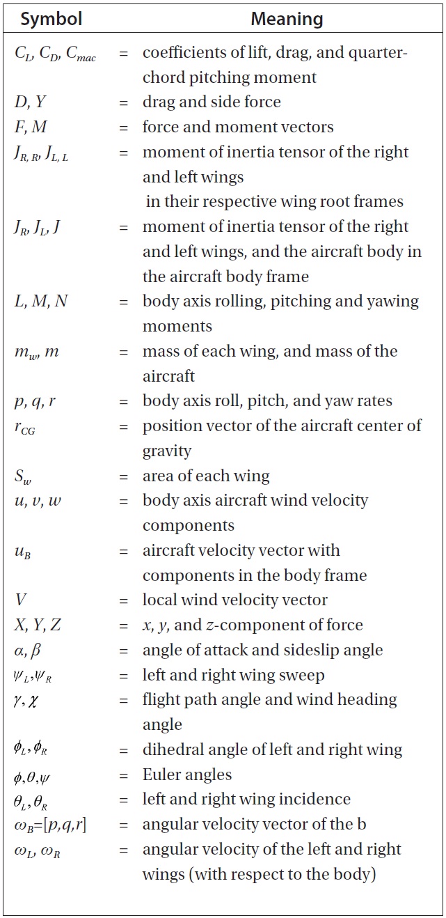
List of Symbols
has the potential to be adapted by bird-scale micro aerial vehicles (MAVs) to significantly improve their portfolio of maneuvering and mission capabilities.
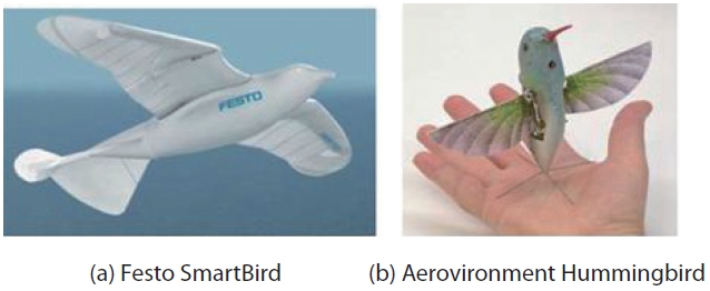
The present review paper focuses on bird-scale flight, and complements the aforementioned papers. It is worth noting that although bird-like aircraft, such as the Festo SmartBird and the Aerovironment Hummingbird, have been developed in the recent years (see Fig. 1), and non-flapping aircraft have drawn considerable inspiration from bird flight, the academic literature on the
In this paper, we review flapping flight of birds from a flight mechanics and control perspective. We review the first principles of flapping flight, and present results on stability and control from the literature. In Section 2, we derive the equations of motion of a flapping wing aircraft. In Section 3, we review flapping wing kinematics. Stability and control of flapping flight are discussed in Sections 5 and 6. Two case studies, the Festo SmartBird and a robotic bat testbed developed by the authors, are presented in Section 7.
In this section, we state the equations of motion for a rigid flapping wing aircraft. The reader is referred to [17] for a complete derivation, and to [16] for a derivation of the equations of motion of an aircraft with
Two approaches are commonly used to model the kinematics of a flapping wing. The first and more common approach starts by identifying the
The second approach is more convenient and models the wing motion as a composition of standard Euler rotations. Wing motion represented by Euler rotations is not difficult to visualize. In fact, it directly describes the physical facets of flapping motion, viz., lead-lag, flapping (up-and-down beating), and twist.
Let the matrix T
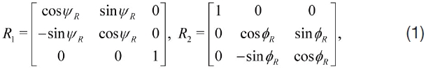
The following rotation matrix connects the right-wing root frame to the body frame:

A similar matrix T
2.2 Local Velocity and Force Calculation
Without any loss of generality, consider the right wing of an aircraft, with (semi) span
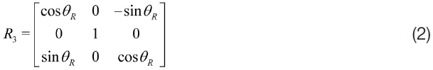
The angular velocity perceived at a spanwise strip at a distance y along the span is given by
and the local velocity at that strip on the right wing is

where
and

where


Detailed expressions for

The total aerodynamic force and moment are obtained by integrating the above expressions, performed in practice by using strip theory [28].
In the following equations, given a vector
Let
and the CG variation is given by

This CG variation could play an important role in cases where the wing weight is substantial and where the CG position is used as a control variable, as in [10]. The CG variation is rarely used by birds, but can be used by insects and insect-size aircraft. It is also used for controlling underwater vehicles.
Therefore, the equations of rotational motion are given by [17]
where
and
In the above equations,
The kinematic equations relate the angular velocity of the aircraft to the rates of change of the Euler angles:
The equations which relate the position of the aircraft to its translational velocity are essentially decoupled from the flight dynamics, and are given by
Finally, the flight path angle (
The aerodynamic model presented by DeLaurier [28] is one of the most widely used aerodynamic models in the flapping flight literature. It incorporates the unsteady added mass effect, delayed stall as well as downwash due to a finite wing. The model is in the form of explicit analytical formulae for computing the forces and moments at every span-wise station on the wing, and the blade element theory is used for computing the net forces and moments. The model is limited by its use of a linear
Goman and Khrabrov [29] presented a model for an oscillating airfoil that is applicable to high
Another popular model used in the literature is the finite state model of Peters and co-authors [31,32], which is motivated by and improves upon the classic model of Theodorsen [33]. In particular, instead of using Theodorsen’s function, the finite state approximation yields a closed-form analytical model.
Goman and Khrabrov’s model offers at least two advantages over the other existing models. First, the model is cast in the form of a single ordinary differential equation (ODE) and two algebraic equations, one each for lfte and the quarter chord pitching moment. The state variable for the ODE corresponds, physically, to the chordwise location of flow separation on the airfoil. Therefore, the model is quite easy to implement as part of a numerical routine. Second, the model is inherently nonlinear and applicable to poststall conditions.
The following equation describes the movement of the separation point for unsteady flow conditions

where τ1 is the relaxation time constant, τ2 captures the time delay effects due to the flow, and
There is, unfortunately, no simple expression for the sectional drag coefficient. Assuming laminar flow on the wing, the sectional drag coefficient can be written as
where
is the chordwise Reynolds number, and
3. Flight Mechanics of Flapping
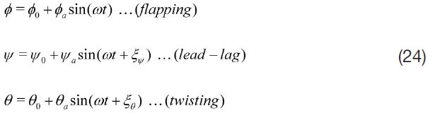
The kinematics of flapping are different in forward flight and hover. In forward flight, the wing primarily flaps and twists, and the lead-lag motion, if any, is strictly for the purpose of control. On the other hand, while hovering, the lead-lag motion is as important as the other two degrees of freedom. In this section, we separately consider simple theoretical models of forward flight and hovering. The purpose of this modelling is to understand the phase relations between the three degrees of freedom, and determine ways to choose the amplitude and bias value of each degree of freedom.
In this section, we consider a rigid wing. Since the phase relations between the different degrees of freedom are independent of the spanwise location on a rigid wing, we consider a single representative spanwise location. Without loss of generality, suppose that the angle of attack of the aircraft (defined with respect to the fuselage reference line) is zero. Then, the local velocity vector

not counting the effect of
so that
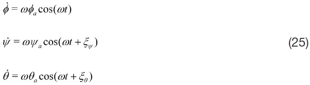
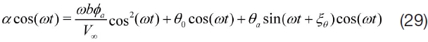
It is worth noting that sinusoidal functions in the above expression can be generated using nonlinear oscillators, such as the central pattern generator (CPG) networks described in Sec. 6. Then, the local angle of attack is given by
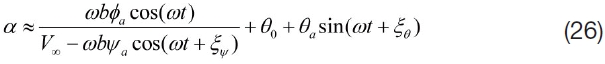
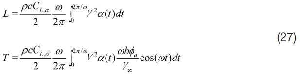
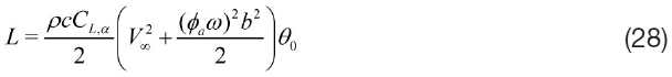
Assuming linear a erodynamics and ignoring the added mass effect, the cycle-averaged values of lift and thrust are given by
where
In forward flight, we set

Substitution into (27) yields the following expression for cycle-averaged values of lift:
We deduce that the average value of lift at a given
The role of the phase difference
It follows that thrust is maximised when we choose
The cycle-averaged value of thrust is given by
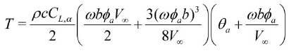
The above results demonstrate that both thrust and lift increase for a given

The above results also suggest an interesting point: it is possible, at least in principle, to produce thrust without using pitch oscillations, i.e., by setting
Remark: The term

is usually referred to as reduced frequency, and

is a scaled version of the
In hovering flight,
Clearly, in order for α to be finite and the cycle averaged lift in (27) to be positive, we need cos(
Remark: The lead-lag motion is a secondary motion in forward flight. The phase relationship obtained here for hovering is indeed used in forward flight as well, e.g., in the CPG-based scheme in [34].
3.4 Force Production during Fast Flight and Hovering
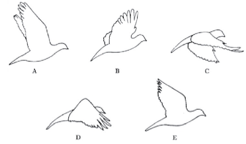
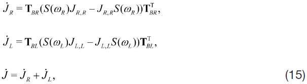
Although the preceding discussion in this section derived conditions under which positive lift and thrust can be generated in a flapping cycle, it did not specifically highlight the distribution of forces in a given cycle. A typical flapping cycle consists of two strokes: a downstroke where the wing flaps down in forward flight (or forward in hovering flight), and an upstroke. Figure 2, taken from [6], shows the typical flapping cycle of a pigeon in forward flight. Sketches (A - C) show the downstroke, while (D - E) show the upstroke. The wing produces both lift and thrust predominantly in the forward downstroke. During the upstroke, the wing still produces some lift, but little or no thrust. Note the bent outer segment in Sketch D: this is a consequence of a degree of passivity in its hinging at the root, i.e., where it is attached to the inner wing. This folding of the wing reduces the drag produced during the upstroke. For a small part of the upstroke, the wing tip does provide a small amount of propulsive force, presumably due to a delayed reversal of motion as compared to the inner wing.
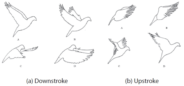
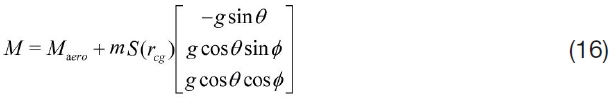
Figure 3 shows the downstroke and upstroke in slow flight (which is not exactly hovering, but a close analog). In slow flight, the role of upstroke and downstroke are reversed. A bulk of lift and thrust are obtained from the
This discussion serves to illustrate a limitation of the discussion in the previous section where the kinematics of hovering were modelled using a first-principls approach. The effects of the rapid wing “flick” are nearly impossible to capture in that framework, but it provides a bulk of the propulsive force and therefore cannot be ignored in force and moment calculations. Such phenomena represent a challenge even to the general aerodynamic modelling of flapping flight.
4. Effect of Nonlinear Aerodynamics and Wing Flexibility
There are several important nonlinear effects that affect the aerodynamics of flapping wings. Broadly, their influence depends strongly on the Reynolds number, Re, i.e., on the size and speed of aircraft. The contributions themselves can be split into two sets: (1) those that alter the circulatory lift, such as by deforming the
The aerodynamics at moderate to high Reynolds numbers (Re>104) are dominated primarily by traditional circulatory mechanisms of lift and thrust generation. The other significant contributor is the added mass effect, which may contribute up to 20% of the net aerodynamic force on the aircraft, depending on the weight of the aircraft.
The delayed stall effect primarily leads to flapping-phasedependent hysteresis in the
The aerodynamics at low
The effectiveness of the unconventional mechanisms listed above is primarily a result of the rapid flapping of insect wings. Whereas birds and bats (high
4.2 Effect of Wing Flexibility on Force Production
Wing flexibility affects the efficiency of flapping flight in three ways, by changing (a) the local wind speed, (b) the local angle of attack, and (c) the phase relations between twisting, flapping and lead-lag. To overcome the detrimental effects of this altered phase relationship, a different phase relation from that of a rigid wing must be commanded at the wing root [35].
A comprehensive experimental study on the effect of flexibility on flapping wing propulsion was performed by Heathcote, Gursul, and co-authors [36,37]. They considered three wings: inflexible, flexible, and highly flexible. For spanwise flexibility, their results showed that a moderate degree of flexibility offers a considerable improvement over a rigid wing, but a highly flexible wing shows a considerable deterioration in performance. They point out a close correspondence between the Strouhal number (measured as a function of mid-span amplitude), and force production and efficiency. The propulsive efficiency, in particular, peaks for
For chordwise flexibility, they observed that although the thrust produced by the wing increases with increasing flexibility, so does drag. Thus, a moderate amount of flexibility is still the optimal configuration.
Flexibility plays another role in flapping flight, namely reducing the sensitivity of the fuselage to gusts [38] and periodic disturbances from flapping. Passive flexible joints are known to help in flow control and delaying wing stall. As shown in Sec. 3, they also help help the wing to generate lift and thrust through unconventional mechanisms.
There are very few results describing a formal stability analysis of flapping flight. A probable cause for this paucity is a belief that the stability of an aircraft in flapping flight can be related to that in gliding flight, under the assumption that flapping frequencies typically exceed the natural modal frequencies of the airframe [39]. This is occasionally used to justify a quasi-steady modelling of flapping flight aerodynamics. It is instructive, therefore, to review the stability of bird-sized aircraft in gliding flight.
5.1 Stability of Gliding Flight
Birds lack a vertical tail, which could potentially render them inherently unstable in yaw, depending on the relative location of the center of gravity and the wings. It has been argued by Taylor and Thomas [38] and Sachs [40-42] that birds are laterally-directionally stable despite the absence of a vertical tail.
The stability of birds comes from three sources: (1) drag, (2) lift, and (3) pendulum effect. Taylor and Thomas [38] showed that drag and pendulum effect are the dominant contributors to stability. The wing itself, according to them, is sufficient to provide longitudinal stability provided it is located behind the center of gravity. Sachs [41,42] derived analytical approximations to the standard flight dynamic modes (short period, spiral, Dutch roll), and showed that the wings are indeed sufficient to provide even lateral-dynamic stability. The stability is largely a result of a favorable placement of the CG with respect to the wing.
In contrast with the arguments in the aforementioned references, Paranjape, Chung, and Selig [17] argued that birds would most likely be laterally-directionally unstable under routing flying conditions. The nature of the instability, arising from the Dutch roll mode, depends on the wing dihedral angle. For large dihedral angles, the Dutch roll mode is indeed stabilized, but such large dihedral angles are rarely used during gliding flight in the midst of soaring or cruising.
Wing flexibility is believed to play a role in stabilizing the airframe, reducing its sensitivity to gusts, and in improving the performance. It was shown by Paranjape and coauthors [16] that flexibility does not necessarily bring about a significant improvement in the performance, and can in fact degrade certain metrics such as the coordinated (zero sideslip) turn rate by reducing the trim speed for a given tail setting. Moreover, unless the wing is highly flexible, there is no qualitative difference in the stability of rigid and flexible wings. Therefore, it is safe to conclude that wing flexibility helps in making the wing and the aircraft lighter, improves the efficiency of passive mechanisms, and even aids flow control, but does not, by itself, improve the traditional flight mechanic performance metrics and stability.
In [43], the authors used an approach identical to [17], but replaced the aerodynamic model with a high-drag model. They demonstrated that the lateral-directional dynamics can be stabilized by drag. In fact, increasing the drag coefficient alone can stabilize the dynamics completely [44].
5.2 Stability of Flapping Flight
The stability of the airframe during flapping flight has been as much a matter of contention as that of gliding flight. Taylor and Thomas [39] argued that flapping wing aircraft are stable longitudinally as well as laterally-directionally, although they lack a vertical tail. The stability in pitch is largely a consequence of the horizontal tail, but is also a consequence of the flapping kinematics [45]. Mwongera and Lowenberg [45] argued that forces arising from circulatory mechanisms tend to be stabilizing, while those that arise from translational mechanisms (such as the unsteady added mass effect) do not contribute to stability. Consequently, they concluded that flyers such as birds tend to be stable, while insects do not tend to be stable. The survey of the stability of insect flight in [2] complements this observation. A study of the modal structure of longitudinal insect flight dynamics by Leonard [46] showed that the instability in insect flight arises primarily from a slow mode.
Flapping motion gives rise to limit cycles rather than equilibria in the state-parameter space. Stability analysis of limit cycles is performed by computing the Floquet multipliers of the linearized dynamics about the limit cycles (much like the eigenvalues of the linearized dynamics about equilibria) [47].
Bifurcation analysis is one of the most sophisticated and generic methods for analysing the global stability of nonlinear systems. Numerical continuation methods are used to compute the steady states (equilibria and the limit cycles) of the system, together with the corresponding eigenvalues or Floquet multipliers. Bifurcation and continuation methods have been used widely to predict instabilities in flight dynamics, aircraft structures, and integrated aircraftstructure- propulsion systems [48].
The first application of bifurcation methods to flapping flight was reported recently by Mwongera and Lowenberg [45]. They considered an MAV consisting of two wings, each with a span of 10cm, and a fuselage, but no tail. They used continuation and bifurcation methods to study the stability of the longitudinal flapping dynamics for different flight conditions as well as for varying the longitudinal position of the wings.
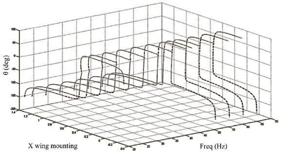
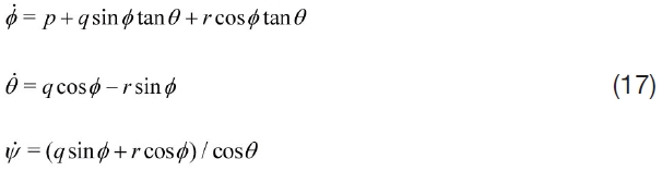
Interestingly enough, Mwongera and Lowenberg’s study concluded that the longitudinal stability depends primarily on the flapping frequency of the wing, with secondary dependence on the longitudinal position of the wing. The latter observation is in stark contrast to the conventional understanding that placing the wing behind the CG ensures pitch stability and vice-versa. In this particular case, it was seen that the lead-lag motion of the wing supplied the necessary stabilizing moments. Moreover, the observed instabilities were largely benign. Figure 4, reproduced from [45], shows the flapping limit cycle amplitudes, together with their stability, as a function of the flapping frequency and longitudinal position of the wing. The unstable regions in Fig. 4 are obtained via period-doubling or Neimark-Sacker bifurcations, which give rise to quasi-periodic behavior [47].
Dielt and Garcia [49] reported a stability analysis of the longitudinal dynamics of a bird-sized ornithopter with a wing span of 72cm. They observed unstable longitudinal dynamics, where the instability was divergent, and the corresponding eigenvector affected all longitudinal states more or less uniformly. The unstable mode was fast (compared to the slow unstable modes in the prior references in this section). Additionally, a stable phugoid-like slow mode was also detected, along with a fast stable mode.
One could ponder about the possibility of a correlation between the stability of flapping and gliding flight of an aircraft under identical conditions (flight speed and angle of attack). There is no conclusive evidence to suggest any correlation. The most obvious analog is flutter: a wing whose plunging and twist dynamics are themselves stable in isolation can still undergo flutter due to adverse phase relationships between plunging and twisting. Morever, from the work of Mwongera and Lowenberg [45], it appears that an airframe that is unstable in gliding could be rendered stable due to flapping. Whereas the lack of a correlation does not appear surprising, it strikes at the root of the rationale behind quasi-steady modelling of flapping flight for stability analysis. Quasi-steady modelling may not work for stability prediction because it leaves no room for instability induced by adverse phase relations between the different elements of the flapping flight dynamics, since it implicitly assumes a stably beating wing interacting with an approximately static fuselage.
Moreover, quasi-steady modelling of the aerodynamics is likely to yield erroneous estimates even of the performance, because medium and large sized birds flap their wings at frequencies which are comparable to the natural frequencies of the air frame. This is one of the reasons why unsteady aerodynamic modelling of flapping wings is essential for analysing bird flight.
In this section, we review recent work on control of flapping flight. Specifically, we focus on two aspects of control: the choice of control inputs and the choice of control methods.
Control of gliding flight appears at first sight to be no different than the control of conventional fixed wing aircraft. However, there are some crucial differences: (1) birds lack a vertical tail and a rudder, and (2) the control system in birds is overactuated. In fact, most birds can exert at least eight control inputs: three degrees of freedom on each wing and two on the horizontal tail (rotations about the in-plane axes). Moreover, birds can control the deflections of their wing leading edge and trailing edge feathers, as well as feathers on top of the wing surface. Together, the feathers play the roles of ailerons, trailing edge flaps, leading edge slats and wingtop spoilers on conventional aircraft. Thus, strictly speaking, the problem of matching the desired control input to the appropriate control surfaces represents a problem in control allocation in over-actuated systems [50]. To the best of our knowledg, the literature is devoid of reports wherein this approach has been applied bird-scale MAVs.
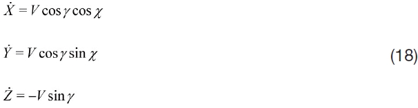
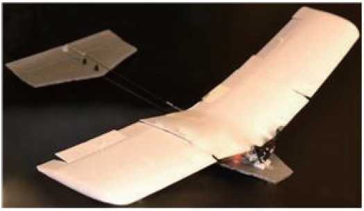
In order to judge the capabilities and limitations of control inputs available to birds, it is occasionally instructive to consider their reverse-engineered instances in the MAV literature. For example, Abdulrahim et al. [51] optimized the wing twist actuation for a flexible membrane-like wing for achieving a rapid roll rate. Paranjape, Chung and coauthors [16, 17] developed an MAV concept which uses the wing dihedral for longitudinal as well as lateral-directional control. The concept shed additional insight into the roles of quarter chord pitching moment and trailing edge flaps in yaw control, and was flight tested successfully [18]. The MAV developed by the authors has been shown in Fig. 5, while Fig. 6 shows a perching maneuver performed by the MAV using articulated wing-based control. The Festo SmartBird (cf. Sec. 7) uses a two-degree of freedom horizontal tail for pitch and yaw control, and the wing dihedral is varied symmetrically for controlling the flight path.
Gliding is important in birds because it helps to conserve energy in flight. It allows birds to extract energy from the surrounding air flow to increase their endurance, a process known as dynamic soaring [53]. Even without the possibility of dynamic soaring, which requires specific wind conditions, it was shown by Sachs [54,55] that switching between flapping and gliding flight can in fact yield a much improved performance, even in terms of the flight speed, over optimized steady state flapping flight.
Once the control inputs are chosen, the control problem involving stabilization and tracking can be solved by any of a vast number of well-established methods, although methods such as adaptive control [56] or dynamic inversion [18,57] may be required to address problems arising from nonlinearities from an unconventional choice of control inputs. Occasionally, if the wing is highly flexible, a control approach which incorporates wing deformation may need to employed to stabilize the elastic dynamics of the wing and
[Table 2.] Control Inputs from the Literature
Control Inputs from the Literature
ensure that it produces the desired force and moment [66].
6.2 Choice of Control Inputs for Flapping Flight
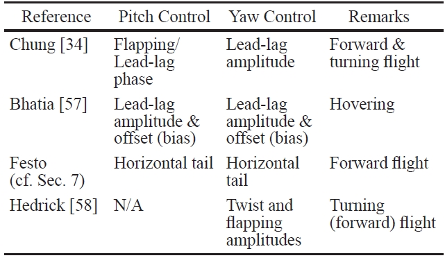
The modelling in Section 3 shows that there is a wide variety of possible control inputs for flapping. They are listed in Table 2, together with their primary effectiveness. We also indicate sources in the literature where they have been employed.
There is clearly a considerable diversity in the choice of control inputs. Chung [34] and Bhatia [58] used the kinematics of lead-lag motion of the two wings to control the motion. In fact, Bhatia [58] demonstrated that, for hovering, LQR control of the lead-lag motion alone is more robust than LQR using larger sets of control parameters. This is to be expected since lead-lag motion is the primary wing motion during hovering flight. Chung and Dorothy considered forward and turning flight in [34], and although their choice of control variable was motivated only by physical intuition, it was seen to be equally effective. In addition to lead-lag control, they leveraged wing beating frequency, the phase difference between flapping and pitch, and flight mode switching to accomplish multiple tasks, including altitude/ velocity regulation and smooth turning.
The SmartBird developed by Festo (cf. Sec.) used a V-tail for pitch as well as lateral-directional control. Therefore, despite flapping-based propulsion, the three- axis control of the SmartBird was essentially identical to that of a fixed wing aircraft.
Hedrick and Biewener [59] observed the turning flight of cockatoos and cockatiels, which differ considerably in size and speed. They observed that both birds used asymmetry in the flapping and feathering amplitudes for roll and yaw control. This can be explained along the lines of dihedralbased yaw control mechanism proposed in [17]. Asymmetric feathering yields direct roll control, but very little yaw control. On the other hand, asymmetric flapping (i.e., asymmetric dihedral) provides direct yaw control, but very little roll control. Therefore, feathering and flapping act as independent roll and yaw control mechanisms, respectively. The reader is referred to Orlowski and Girard [2] for a similar table of control inputs found in the liteature on
In contrast to birds, whose wings are structurally more or less undeformed, bats deform and camber their wings significantly in flight, as demonstrated by Breuer and coauthors [60]. Their wings are cambered and fully stretched during downstroke, and folded inwards during the upstroke. This helps to reduce the drag, and particularly since the upstroke contributes no thrust either. Birds are known to fold their wings to maneuver rapidly, such as to perform barrel rolls, but not systematically in a single stroke as in the case of bats. The primary reason is that bat wings are made of
skin, which acts like a flexible, malleable membrane, while feathers that make up bird wings are more or less rigid. This feature may contribute to a bat’s ability to complete a 180deg turn in approximately three wingbeats [60].
For turns, birds as well as bats bank considerably, turning the lift vector inward [6,61]. However, banking is not solely responsible for turning. D?az and Swartz [62] estimated that, for bats, at most 70% of the required turning force was due to banking. The remaining portion was the result of a crabbed turn - changing yaw orientation during upstroke and flight direction in the subsequent downstroke [62]. In contrast, studies of turns performed by the Parajape et al. [16,17] showed that when asymmetric dihedral (or flapping angle) is used in gliding turns, the body bank angle is considerably smaller (less than 20deg) even for large turn rates.
6.3 Control Methods for Flapping Flight
The survey papers by Orlowski and Girard [2], and by Taha, Hajj and Nayfeh [3] give a comprehensive review of control methods employed commonly for flapping flight aircraft. In this paper, we review two control approaches, each of which sheds light on a fundamental aspect of controlling flapping flight. The first approach is based around central pattern generators (CPGs), and uses synchronization properties of coupled oscillators [34]. The second approach is based on linear quadratic regulator (LQR) control, and indicates the importance of specific control effectors and on the relevance of specific state variables for feedback.
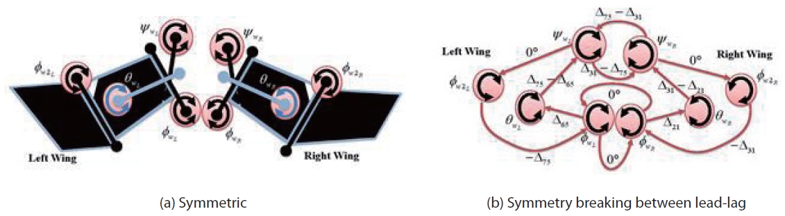
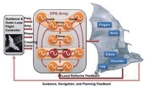
Chung and Dorothy proposed a CPG-based controller, leveraging the properties of the symmetric Hopf oscillator [34]. The key idea was to produce smooth signals for multiple motions while allowing for great flexibility in toplevel controller design. Such a coupled oscillator network could easily incorporate frequency, amplitude, and phase difference modulation. They used all three types of control logic - frequency for velocity control, amplitude for yaw control, and phase difference for roll and pitch control. Such a CPG network could also reproduce intra-wingbeat frequency controllers like the split-cycle [11] without requiring any analytic solutions [63]. Figure 7 shows the schematic of a CPG array for the two wings. The first plot shows a nominal, symmetric configuration for forward flight. The nominal phase differences were derived in Sec. 3. The second plot shows a configuration where the phase difference between the lead-lag motion of the two wings is used as a control input, with the plunging motion of the two wings retained in sync. This is not a unique choice of control inputs, but serves to illustrate how the phase differences and symmetry-breaking can be honed for control. A block diagram showing an implementation of CPG-based control is shown in Fig. 8.
Bhatia and co-authors [58] presented an LQR-based controller for hovering flight in the presence of gusts. Their metric for evaluating controllers was the maximum speed of a transient gust that the controller could withstand. They designed an LQR controller and systematically scaled the penalty functions and varied the choice of control inputs, while evaluating the maximum tolerable gust speed. They concluded that controlling the amplitude and bias of leadlag motion is not just sufficient but also the most effective way of achieving tolerance to gusts. They also demonstrated, at least for their particular model, that it is necessary to feed back angular positions and angular rates for increased gust tolerance, while translational position and velocity feedback play a comparatively insignificant role. The final version of their controller (obtained after the parameter study) yielded satisfactory tolerance to longitudinal gusts whose speeds matched the tip speeds of the wing, and to lateral gusts with a speed equal to a third of the tip speed.
In this section, we will describe two examples of mechanical implementation of bird-scale flapping flight - the Festo SmartBird and a robotic bat testbed developed at the University of Illinois at Urbana-Champaign (UIUC). The purpose is to consider practical design issues that arise in the implementation of the aforementioned ideas, which were presented largely from a theoretical standpoint, as well as solutions used in practice.
The SmartBird, designed by Festo, is probably the first successful flapping wing remote-controlled aircraft which mimics some relevant characteristics of avian flight (in this case, a sea gull). The aircraft incorporated several technologies, and most details are unpublished. We will summarize some relevant design features, gathered from the product brochure, and relate them to the theoretical results presented in the previous section.
Each wing of SmartBird has two segments. The flapping motion of the outer segment is not synchronized actively with that of the inner segment, but is instead coupled to the inner segment passively. The twisting motion of the wing, however, is controlled actively for optimizing the lift and thrust produced during a flapping cycle. No additional lifting devices are used. Interestingly, the wing is designed to be rigid in torsion despite its size, although reasons for this design choice are unknown.
The inboard segment primarily generates lift, while the outboard segment provides thrust. This separation of roles is also seen in large birds such as sea gulls and swans. The SmartBird utilizes a horizontal tail with two degrees of freedom: it can deflect about the transverse axis for pitch control, and about the longitudinal axis of the aircraft for yaw control. Roll control is achieved by controlling the torsion motion of the two wing.
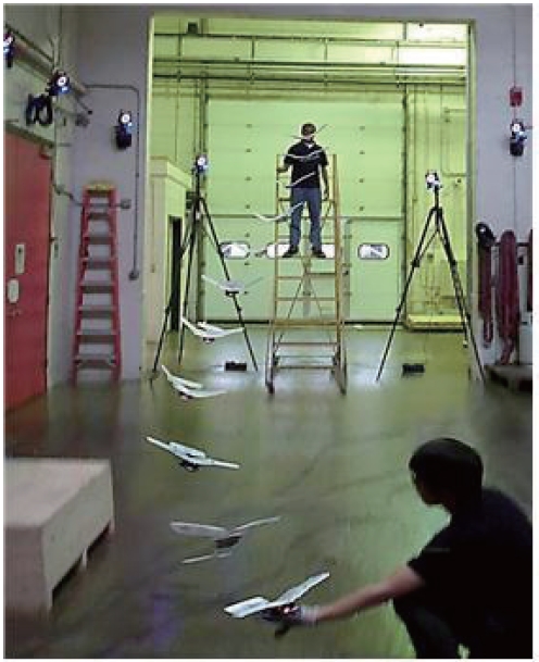
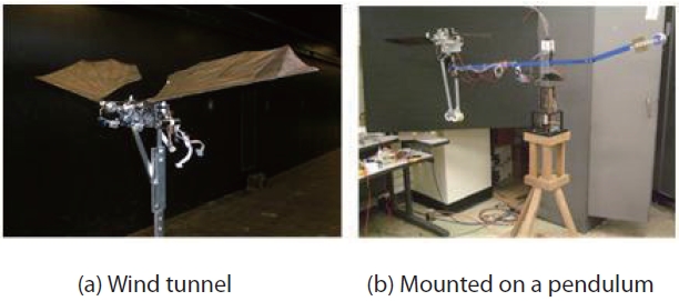
The RoboBat was developed to investigate the effectiveness of different control strategies on forces and moments [27,64,65]. RoboBat incorporates six degrees of freedom (flapping, lead-lag, and pitch for each wing), which would be synchronized and controlled via a CPG network. Each wing is driven by a single DC motor, while the phase difference between the different degrees of freedom is controlled by servo motors. Figure 9 shows the Robotbat testbed mounted
in a wind tunnel for early testing, as well as the current s experimental setup where it is mounted on a rotating 3-DOF pendulum.
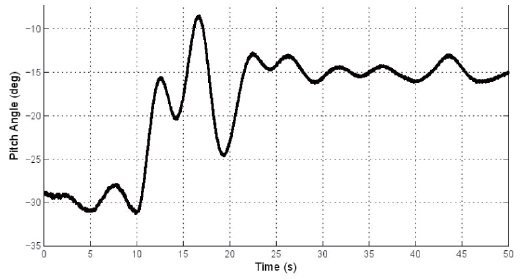
In order to test closed-loop CPG control, it was placed on a compound pendulum, restricting the system to longitudinal modes only. The Quanser-built encoder interface integrated in the pendulum provided orientation and velocity feedback. Phase differences between flapping and lead-lag proved to be effective in stabilization and control [27]. An example trajectory for pitch control is shown in Fig.10. However, the system was not as sensitive to control input as indicated by prior simulations, as the compound pendulum system increased the pitch moment of inertia.
8. Conclusions and Future Work
In this paper, we surveyed the literature on flapping flight of birds and bird-like airplanes from a flight mechanics perspective, in a tutorial-like setting. Stability and control of flapping flight were addressed with insightful case studies from the literature. Open problems in flapping flight incover both stability and control. In particular, very little is understood about lateral-directional stability of birds and bird-scale aircraft in the flapping phase. Quasi-steady aerodynamic modelling, which forms the cornerstone of a considerable body of work on the modelling and analysis of flapping flight, presents a strong possibility of erroneous stability and control results in bird-scale flapping flight due to a close match between the typical flapping frequencies and the natural frequencies of the flight dynamics of the air frame. Flapping wing aircraft, unlike typical fixed wing aircraft, are over-actuated, which presents as yet largely unsolved problems in control allocation. Despite these shortcomings in our knowledge of flapping flight, there are some instances of flapping wing MAVs being developed and flown successfully by the academia as well as the industry. A deeper understanding of stability, coupled with sophisticated schemes to optimally uilizse the multitude of control inputs, will significantly enhance the performance and maneuverability of flapping wing aircraft in the future.


![A typical flapping cycle of a pigeon in forward fight, from Brown [6].](http://oak.go.kr/repository/journal/11296/HGJHC0_2012_v13n3_267_f002.jpg)
![A typical flapping cycle of a pigeon in forward fight, from Brown [6].](http://oak.go.kr/repository/journal/11296/HGJHC0_2012_v13n3_267_f003.jpg)
![Bifurcation diagram showing the pitch angle amplitude as a function of the flapping frequency and the longitudinal position of the wing [45]. Solid points indicate stable limit cycles, and dashed lines indicate unstable limit cycles.](http://oak.go.kr/repository/journal/11296/HGJHC0_2012_v13n3_267_f004.jpg)
![Perched landing on a human hand, performed by an articulated wing MAV.[65]](http://oak.go.kr/repository/journal/11296/HGJHC0_2012_v13n3_267_f006.jpg)

![CPG array for the two wings. The lead-lag, flapping and feathering angles are denoted by ψw, Øw and θw respectively. Under nominal flight conditions, the the lead-lag motion would be out-of-phase with flapping by 180deg, while feathering would lead flapping by 90deg, as shown in Sec. 3. The terms Øw2 represent the second joint in each bat wing, and also ensure that the net phase difference summed over a cycle in the CPG network is zero. The second plot shows symmetry-breaking between lead-lag, with in-phase plunging motion, for lateraldirectional stability and control [34]](http://oak.go.kr/repository/journal/11296/HGJHC0_2012_v13n3_267_f007.jpg)
![Block diagram showing CPG-based control of a bat-like flapping wing aircraft [34].](http://oak.go.kr/repository/journal/11296/HGJHC0_2012_v13n3_267_f008.jpg)