A simple and robust methodology is presented to determine the location and amount of crack in beam like structures based on the incremental particle swarm optimization technique. A comparison is made for assessing the performance of standard particle swarm optimization and the incremental particle swarm optimization technique for detecting crack in structural members. The objective function is formulated using the measured natural frequency of the intact structure and the frequency obtained from the finite element simulation. The outcomes of the simulated results demonstrate that the developed method is capable of detecting and estimating the extent of damages with satisfactory precision.
Damage may be defined as the changes occurred to a structural system including changes to material and geometric properties, boundary conditions and system connectivity either intentionally or unintentionally that negatively impact the current as well as the future performance of that system. It can be introduced to a structure by a number of means including long term degradation of the structures as well as extreme events like natural disasters, fire, accidental or intentional overloading, collision or terrorism activities. The introduction of damage induces instability in the system thereby increasing the risk of unpredicted structural failure causing catastrophic, economic, and human life loss. Hence, in order to maintain the safety and reliability of the structure it is necessary to inspect the condition of the structure regularly.
Several non-destructive techniques are available for the identification of damage in a structure [1] which can be categorized into two groups, viz.; the local damage detection method and the global damage detection method. Local damage-detection methods are either visual or localized experimental methods such as the acoustic or ultrasonic method, magnetic field method, radiography method, eddy current method and thermal field method. All of these experimental techniques require that the vicinity of damage is known a priori and that a portion of the structure being inspected is readily accessible. Subjected to these limitations, these experimental methods can detect damage on or near the surface of the structure. However, in case of health monitoring of civil or aerospace structures, information regarding damage is usually not available before damage identification, and the location of damage may be inaccessible. Hence, the need for quantitative global damage-detection methods that can be applied to complex structures has led to the development of and continued research into, methods that examine changes in the vibration characteristics of the structure. The main idea behind damage detection techniques based on structural dynamic changes is the fact that the modal parameters of a structure are functions of the physical parameters (mass, stiffness and damping) and thus the existence of damage leads to changes in the modal properties of the structure.
Recently a lot of work has been carried out to detect and quantify damage from changes in their modal properties such as, natural frequency, mode shapes and their derivatives. Doebling et al. [2] provided a comprehensive review on work regarding vibration-based damage identification research carried out till 1996. Carden and Fanning [3] presented a follow-up work to the broad and extensive review done by Doebling et al. [2]. Further Fan & Qiao [4] provided a review of the research works carried out till 2010. In most of the studies [5] researchers have used natural frequency as the diagnostic tool as they are easy to measure, and least affected by measurement errors. Messina et al. [6] suggested a standard error of ± 0.15% as a benchmark figure for natural frequencies measured in the laboratory with the impulse hammer technique. In contrast, modal damping and mode shape estimates have error levels as much as 20 times worse in comparison to natural frequency estimates.
The approach for damage detection using vibration data can be categorized into two categories namely, the forward approach and the inverse approach. The forward approach consists in determining the effect of damages on the structural dynamic properties whereas the inverse approach consists of determining damage parameters, such as crack length or location, from changes in the structural dynamic properties. The usual approach in the inverse procedure is to minimize an objective function, which is defined in terms of discrepancies between the vibration data identified by modal testing and those computed from the analytical model [7]. However the mathematical relationship between the structural vibration response and the location and extent of damage is very complex involving a large number of local optima. This makes the problem too difficult to be solved by conventional optimization algorithms such as the conjugate gradient. However, this black box mapping between cause and effect can be solved by recent computational intelligence methods such as the genetic algorithm [7-9], evolutionary algorithm [10], artificial neural network [10-13] and swarm intelligence techniques [14-18] etc.
Particle swarm optimization (PSO) [19] is a relatively new verity of the computational intelligence method, which mimics the collective motion of insects and birds, known as “swarm behavior”, trying to reach an unknown destination. The main advantage of this method lies with its simplicity in terms of the algorithm and requires updating two simple equations whose purpose is to emulate the best global individual found, as well as the best solutions found by each individual particle [18]. Due to its simplicity and convergence speed, PSO has found its application in many complex engineering optimization problems including structural design optimization [20] and structural damage detection [16, 18]. However, the main drawback associated with Standard PSO is that the algorithm may converge into some local optima. This may lead to prediction of wrong result. Therefore, in order to improve convergence into global optima and to improve diversity there has been many works on algorithm refinement and parameter modification.
In this study, an improved version of the PSO Technique called incremental particle swarm optimization (I-PSO) [21] is proposed for structural damage detection and assessment problems. In I-PSO one or more particles are added to the swarm hood after a few iterations until the optimization process returns an acceptable solution quality or until a maximum population size is reached. The newly added particles acquire knowledge about their environment from more experienced particles which are already a part of the swarm. Beginning with a small number of particles provides two advantages: (i) it enables fast learning for the initial population of particles due to the reduced interference effect that a large population provokes [22], and (ii) it may allow the optimal allocation of particles to solve a particular task. A suitable objective function is assumed to reduce the damage assessment problem to an optimization problem, which is then solved by the I-PSO technique to access the condition of damage. Finally, some comparative studies are made for the assessment and demonstration of the algorithms in detecting single and multiple damages in a numerically simulated cantilever beam.
2.1. Finite element formulation of structure
The governing equation for an Euler-Bernoulli beam with negligible damping is given by,
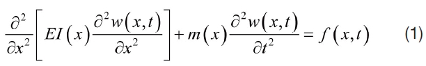
Where
For an

Where, [
The eigen value equation associated with eq.2 is given by,

The solution of this eigen value equation provides
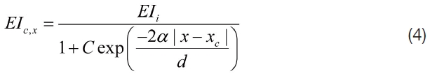
The efficiency of the model-based crack assessment problem greatly depends on the parameterization of crack. It may be assumed that the introduction of crack does not change the mass of the system. The crack is assumed to be uniform across the width of the beam and is fully open. Also, the introduction of crack is assumed to vary local stiffness only. Further change in neutral axis near its vicinity is neglected. For a rectangular beam with a uniform cross section with crack of depth
The damage assessment problem is reduced to a minimizing optimization problem by suitably assuming an objective function. Natural frequencies are easier to measure than mode shapes and the error associated with its measurement is comparatively less. Hence, they are used as damage indicators in this study. The objective function used for this study is the root mean square (RMS) of the ratio of the frequency measured from the intact structure by the frequency obtained from finite element simulation minus one. i.e.
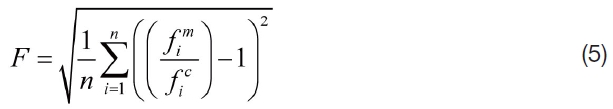
Where,
2.4. Overview of Particle Swarm Optimization
The particle swarm optimization technique is a population based stochastic technique in nature, and primarily used to tackle continuous optimization problems. Numerically, the positions of

And,

During the search process the particle moves to new positions by considering two factors: the best previous position visited by itself denoted by


The velocity and the position of the particle for (


The parameters
Where,
Velocity of the particles is an important parameter that determines the resolution, or fineness, with which regions between the present position and the target (best so far) position are searched. Too high of a velocity for a particle may cause the particle to fly past good solutions, whereas, too low of a velocity may cause the particle to not explore sufficiently beyond locally good regions by trapping themselves into a local optima. Therefore, particles are usually constrained within the range [-

Where
2.5. Incremental Particle swarm optimization (I-PSO)
In the I-PSO algorithm the iteration begins with few particles and one or more particles are added to the swarm hood after every iteration or after specific number of iterations until maximum population size is reached. The newly added particles acquire knowledge about their environment from more experienced particles, which are already a part of the swarm. The social learning strategy is implemented by moving the newly added particle from its initial random location in the search space to the previous best position of a particle called the model particle that serves as a “model” to imitate. The usual practice is to choose the best particle as the model particle although any random particle can be chosen as the model particle. Mathematically, the position of newly added particle

Where,

is the updated position of the newly added particle,

is the original random position of the newly added particle,

is the model particle’s previous best position, and
The random number
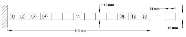
Numerical simulations are carried out to demonstrate the effectiveness of the proposed damage assessment algorithm. A steel cantilever beam with a length of 600 mm and a cross section of 10 mm × 24 mm is selected for the purpose. Bending is considered in the plane of thinner dimension. The Young’s modulus and density is considered as 200 GPa and 7800 kg/m3, respectively. After conducting a convergence study, 20 equal Euler-Bernoulli beam elements are used for finite element modeling. Fig. 1 shows the sketch of the beam with element numbering used in the finite element simulation.
First, six natural frequencies without noise and the first nine natural frequencies with random noise are selected as a damage indicator. These are estimated from finite element simulation. Table 1 shows the first six natural frequencies of the intact beam. Up to 1% random noise is added to the natural frequency data to simulate measurement error. Single and multiple cracked conditions are simulated for the purpose. The results of crack detection are compared for estimating the effectiveness and robustness of the algorithms.
3.1 Performance study of PSO algorithms:
Three cases, as shown in Table 2, are considered for demonstrating and comparing the performances of standard PSO and incremental PSO algorithms.
The measured cracked natural frequencies used for evaluating the proposed inverse procedures are generated numerically by FE simulation. First, six noise-free natural frequencies (Table 2) for the cracked beam are used as input for the algorithm in order to have a fair comparison.
The simulated natural frequencies without noise are used for the construction of the objective function in PSO algorithms. The maximum swarm size for the optimization is set to 50, 75 and 100 for cases C1, C2 and C3, respectively. For the I-PSO, the initial population size is taken as 25, 35 and 50, respectively, for case C1, C2 and C3 and five swarms
[Table 1.] First six natural frequencies of the intact beam (in Hz)

First six natural frequencies of the intact beam (in Hz)
[Table 2.] First six natural frequencies of the Cracked beam (in Hz)
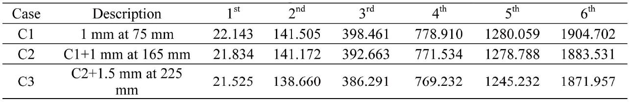
First six natural frequencies of the Cracked beam (in Hz)
[Table 3.] Evaluation of performance of PSO algorithms
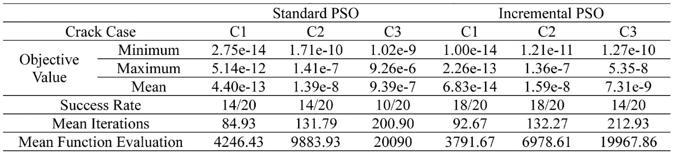
Evaluation of performance of PSO algorithms
are added to the neighborhood at each 5th iteration till a maximum swarm size is achieved. The maximum number of iterations to be carried out are considered as 200, 200 and 300, respectively, for C1, C2 and C3 crack cases. Ring topology is defined as the social network structure. Since the optimization problem used for crack assessment is very complex involving a large number of local minima, it is very probable that the algorithm may stick at some local minima. Hence, we have presented
Also, the algorithms were compared in terms of the
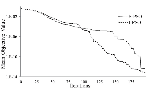
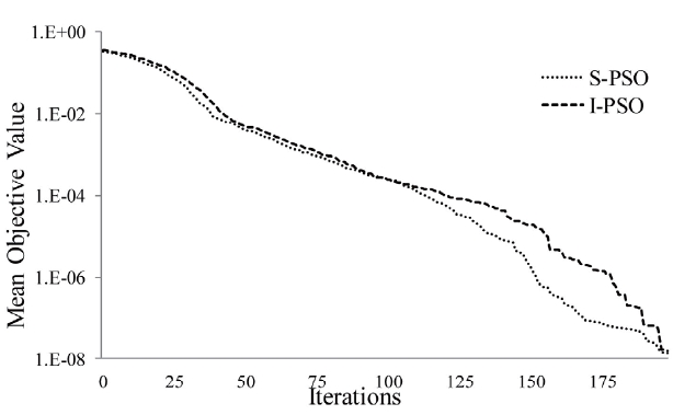
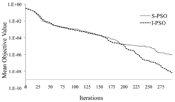
It can be seen from Table 2 and Figs. 2-4 that both the algorithms are able to provide quite an optimized function value in just a few iterations. However, when incremental PSO is compared with the standard one, the former clearly produces a better result due to its higher success rate; lower mean objective value. Though the number of iterations required to achieve the required accuracy is more in the case of I-PSO, the mean function evaluation is less than that of S-PSO.
3.2 Performance of PSO algorithms with noisy natural frequency data
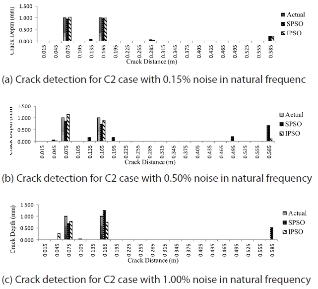
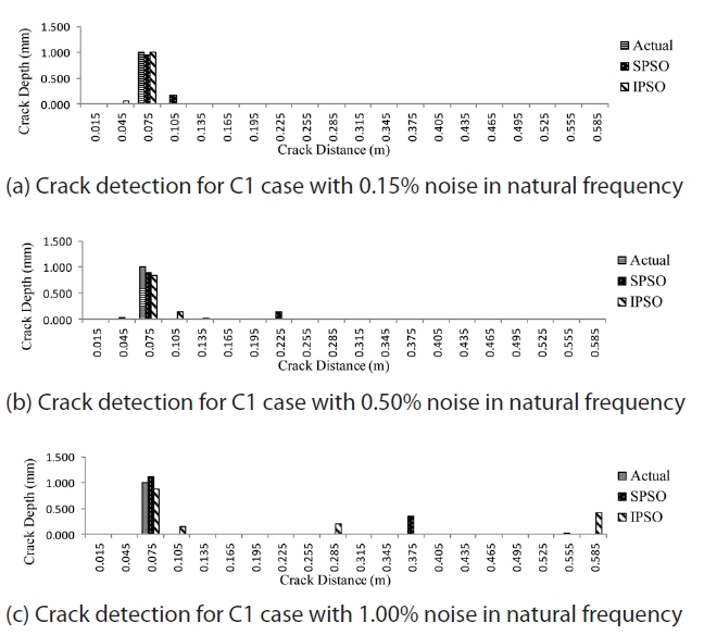
The algorithms are evaluated for their performance in determining crack using natural frequency with measurement error. First, nine frequencies are considered for damage assessment. In order to simulate the experimental cracked frequency for the beam in a realistic way, random errors are added to the calculated frequencies for each of C1, C2 and C3 cases. Three different noise levels with ±0.15%, ± 0.50%, and ±1.0% noise, respectively, are added to the theoretically calculated frequencies. The maximum size of swarm is taken as 150 and the initial swarm size is set to 75 for the I-PSO case. Similar to the section 3.1, the swarm increment strategy is taken as five swarms at the fifth iteration, till the maximum swarm size is achieved. The maximum iteration is set to 300. A total of five experiments are conducted for each case and noise level, and the experiment resulting in the lowest objective value is considered as the final crack scenario. Figs.5-7 present the results of crack detection for each case. The ordinates provide the depth of crack in mm and the abscissa provide the distance of the point from the fixed end in meters. The notations Actual, S-PSO and I-PSO represent the actual crack present in the structure and are detected by the S-PSO and I-PSO algorithms, respectively.
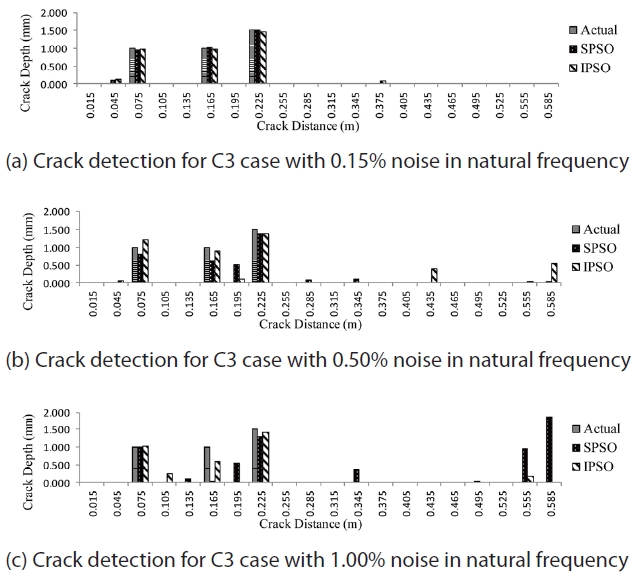
It can be seen from Figs. 5-7 that, both the algorithms perform well in detecting crack locations but the performance of I-PSO is found to be superior to S-PSO in detecting cracks. Though, in some cases both algorithms show a false crack scenario toward the free end but the amount of false damage
is significantly less for I-PSO. Also, crack quantification obtained by the I-PSO algorithm is found to be better than S-PSO. While analyzing the efficacy of both I-PSO and S-PSO for all the cases, it is observed that S-PSO could not detect correct damage locations in some cases [for example Fig.7(c)] and the amount of false damages is quite significant compared to I-PSO. In contrast, I-PSO could consistently detect the correct damaged locations in all cases and the amounts of false damages are comparatively small in most of the cases. Thus, considering the results of all the cases, we can conclude that I-PSO could detect damages more accurately than S-PSO.
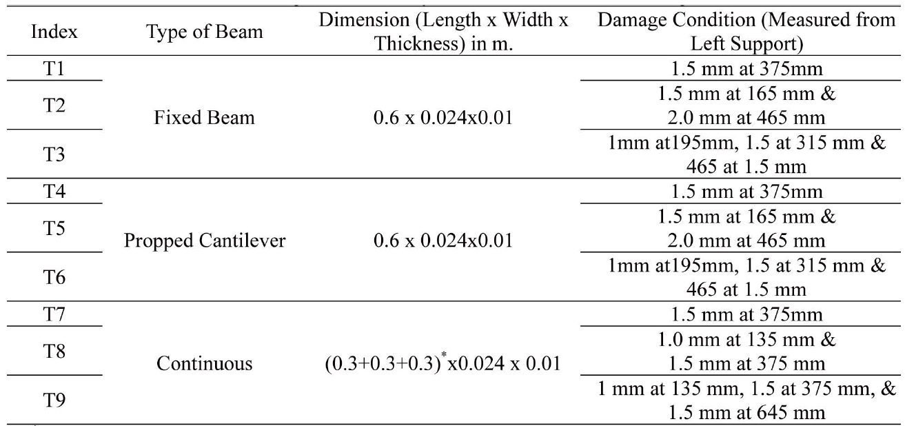
To study the effectiveness of the I-PSO based damage assessment technique, nine cases are considered with varying beam types and damage conditions as shown in Table 4.
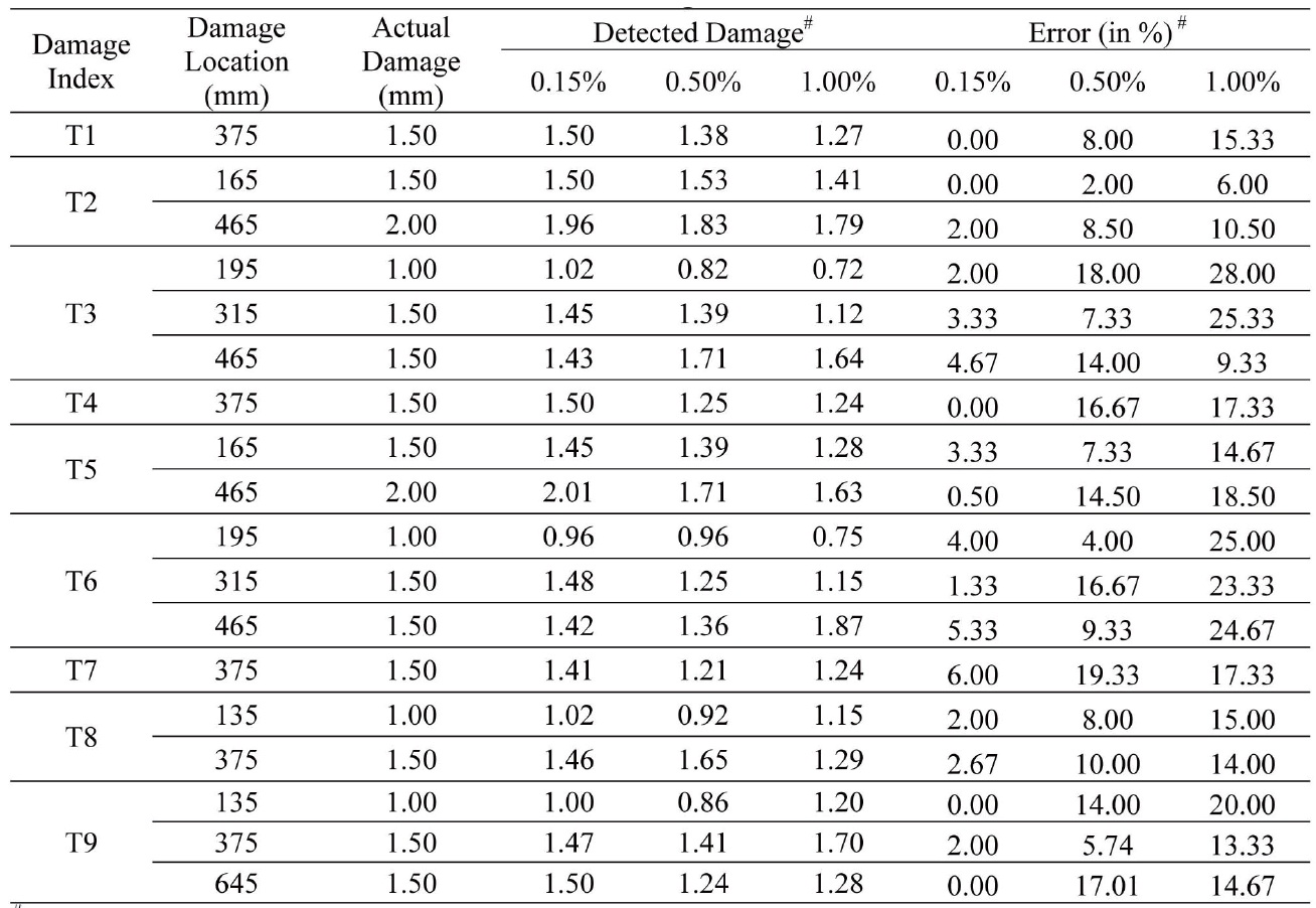
The initial and maximum swarm size, algorithm related parameters and material constants are kept similar to the previous study. The fixed beam and the propped beams are discretized into 20 and the continuous beam into 30 equal Euler-Bernoulli elements. First, nine frequencies are considered for the study. The results are shown in Table 5. The noise level in the natural frequency data is represented as a percentage.
It is seen from Table 5 that the I-PSO based algorithm can identify the correct damaged location with reasonable accuracy.
The error associated with the quantification of damage is below 6% for a noise level of 0.15%, 20% for a noise level of 0.50% and 28% for a noise level of 1.00% in measured frequency data. Though the number of false detections increases with an increase in noise level, its value never exceeded 0.5 mm for the considered noise levels, and hence it is not included in the table for the sake of brevity.
A simple but robust methodology is presented to determine the location and amount of crack in beam like structures based on the I-PSO technique. A comparison is made for assessing the performance of S-PSO and I-PSO for detecting cracks in a cantilever beam like structure. A comparison is also made to check the effectiveness of both variants of PSO in detecting damage when error is present in the natural frequency data. Finally, some additional damage cases are simulated to check the applicability of the I-PSO based damage detection algorithm. The results reveal that the I-PSO based algorithm not only identifies the correct location of the damage but can also quantify the damage with reasonably good accuracy even with noisy frequency data.
[Table 4.] Damage cases to study the effectiveness of I-PSO algorithms

Damage cases to study the effectiveness of I-PSO algorithms
[Table 5.] Results of damage assessment
Results of damage assessment