There have been many attempts at synthesizing nano and micro carbon material from plant derived precursors by pyrolysis. In their effort to obtain different types of carbon nano materials (CNMs), Sharon’s group [1-7] screened plant derived materials like oils, seeds, volatile oils, resins, and fibrous plant tissues, etc.; each material resulted in a different carbon morphology.
Plant fibers are mature xylem tissues, which can help in water and mineral translocation. They are complex permanent dead tissue, made up of four different types of cellular elements, i.e. tracheids, tracheae, fibers, and xylem parenchyma (parenchyma is the only living component of the tissue).
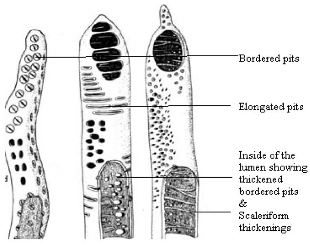
Plant fibers are composed of long narrow tapering cells, also known as Sclerenchyma cells (Fig. 1). They are dead and hollow at maturity, having thick cell walls composed mostly of cellulose and lignin. Fibers are rigid and provide support and occur in many different shapes and sizes, but two main types occur: fibers and sclereids. Fibers are greatly elongated (many times longer than they are wide) cells whose long, tapering ends interlock, thus providing maximum support to a plant. The side walls of fibers are often so thick that the center of the cell (the lumen) is often occluded. Fibers have great tensile strength and yet are also
elastic. These qualities are significant in the flexible support of the plants. Lumen is spacious and extends throughout the length of the tracheid. In some cases, due to the deposition of lignin, the primary wall develops numerous concave depressions called pits, which give the tracheids very special, different morphologies.
Cellulose is the major component of rigid plant cell walls.
The present work is an attempt to study the morphology of CNM obtained from various plant fibers and to compare them with the inherent anatomy of the plant fibers from which they were synthesized.
2.1.1. Synthesis of carbon from plant fibers
Different types of plant fibers i.e. Corn-straw (
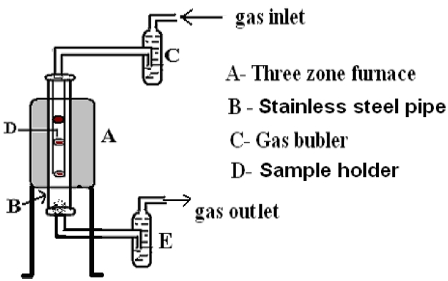
For pyrolysis, a vertical electrical stainless steel furnace of 3 KW was used (Fig. 2). In this furnace, a 1 meter stainless steel tube (B) of 10 cm diameter was inserted. Inside this tube there were three holders, one in each furnace zone, to hold metallic boats that contained the plant material for pyrolysis. Chopped fibrous plant material (50-100 g) was kept in the boat and then inserted into the holder (D) in the furnace. To flush out air from the furnace (E), nitrogen gas was flowed in (C) at a flow rate of 100 cm3 min -1 to create an inert atmosphere. After flowing the gas for 5 min, the furnace temperature was set at 850℃ in order to pyrolize the plant material. Once the furnace reached the desired temperature, the heating was continued for a further 3 h at constant set temperature and then the furnace was allowed to cool down to room temperature. The carbon material was collected from the boat (D).
The synthesized carbon contained some amorphous carbon, which was removed by soaking samples in 12 M nitric acid (72 % pure) followed by soaking in 10 M hydrochloric acid (40 % pure) for 30 min. Then, samples were filtered. The acid treated carbons were repeatedly washed with distilled water until the water showed a neutral pH (6.5-7.0); samples were then filtered. Finally, samples were rinsed with acetone to remove the water and then dried in an oven at 150℃ for 24 h.
2.1.2. Characterization of carbon materials
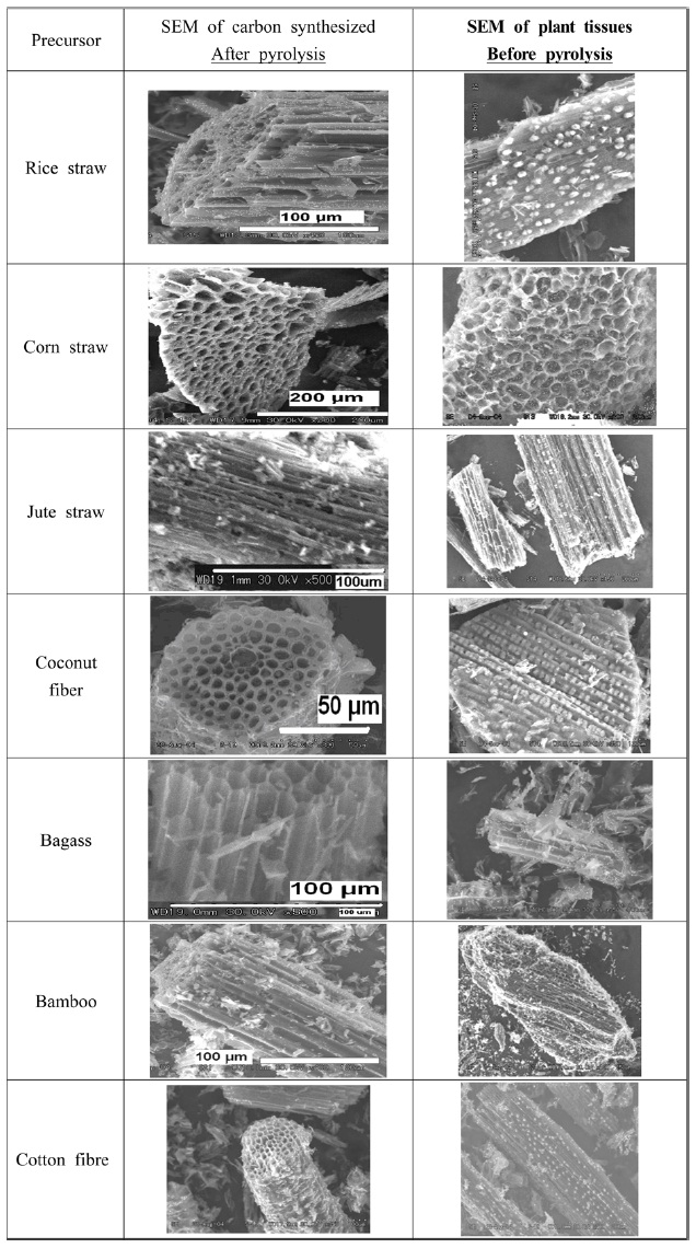
This process was carried out by scanning electron microscope (SEM) using FEI Quanta 2 (prior to pyrolysis, SEM micrographs of plant fibers were also taken), X-ray diffraction (XRD, using a Philips Panalytical Xpert with Kα of Cu (0.154056)), and Raman spectra.
2.1.3. Hydrogen adsorption study by these carbons
The methodology used was the same as described in various presentations of Sharon’s group [1,2].
Materials collected from the boats (D) kept inside the furnace were used for characterization. Pyrolysis of lignin (wood) is known to produce charcoal and a range of other products,
All carbon materials were of micro size, having large pores and channel like structures.
Plant fibers are made up of thick walled sclerenchymatous tissues, trachea, tracheids, and xylem vessels having primary thickening on their walls and phloem fibers. These fibrous tissues have elongated cells with thickened walls. Under SEM in cross sectional view, they show pore like structures, whereas in longitudinal or vertical sectional view they show clear channel like structures.
Since there is a great variation in the chemical composition of lignin, the structure of tracheids and trachea show different types of thickening; even within the same plant, each type of plant material showed slight variation in anatomical structure. Therefore, CNM prepared from plant fibers also showed similar channel like structures, which in cross sectional view gives an appearance of a porous, sponge like entity (Fig. 4).
All the carbon samples show a structure that resembles the tissue structure of the plant material from which they were synthesized. It appears as if, except for the carbon, all the other ingredients, e.g. tyloses present on the surface of the plant tissues and thickening on the cell walls of the tracheids, have sublimed, leaving the carbon skeleton intact. From a study of the series of electron micrographs of the primary xylem cells at various stages of development, it can be suggested that the microtubules are instrumental for the localized thickening of the tracheids [8]. This may account for the presence of a microtubular morphology in the carbonized plant fibers.
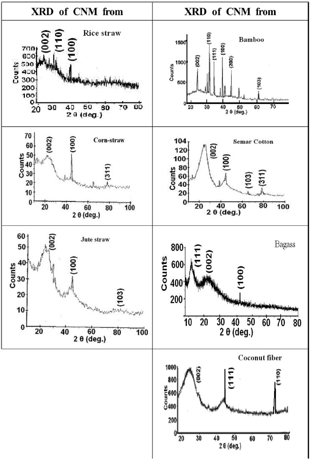
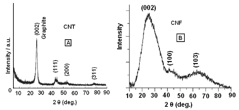
XRD images of carbon materials prepared by the pyrolysis of various precursors are shown in Fig. 5. The characteristic planes for each carbon material are shown in the spectra. If we compare the XRD presented in Fig. 5 with that of the pure carbon nanotube (CNT) [9-12] and pure carbon nanofiber (CNF) [13], presented in Fig. 6, we can see that these images show that CNT has peaks at 26.4°, 43°, 53°, and 78° for (002), (111), (200), and (311) planes, respectively, whereas CNF shows peaks at 26.4°, 42°, and 62° for (002), (100), and (103) planes, respectively. This comparison suggests that XRD for CNT has a very sharp peak for (002) while CNF has a broad peak. Accordingly, it can be concluded that carbon materials obtained from these precursors
possess characters similar to those of CNF, rather than those of CNT. However, confirmatory tests can only be obtained from the transmission electron microscope studies. The broadened (100) and (103) peaks reflect the disordered graphitic character. All the carbon obtained from fibrous plant materials shows the development of a (002) plane, with the exception of carbon obtained from bamboo, which shows a very crystalline character.
3.3. Characterization by micro-Raman spectroscopy
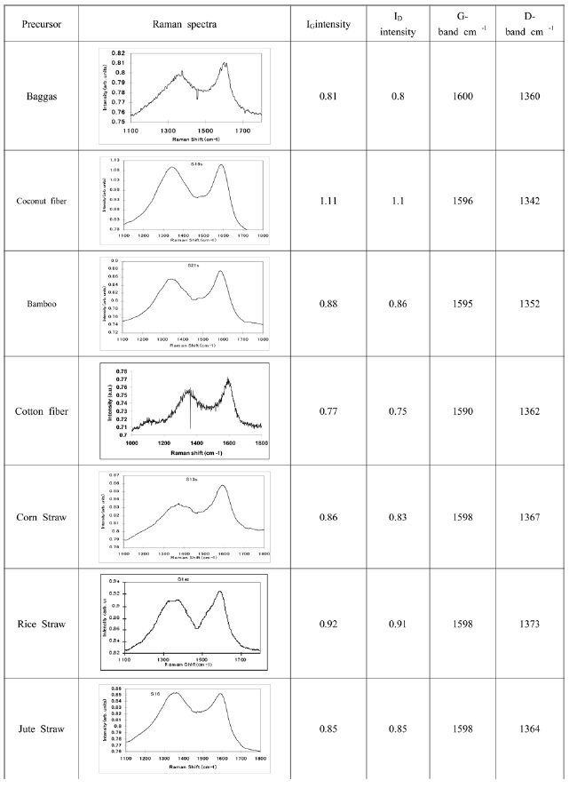
Raman spectra of carbon materials synthesized from various fibrous precursors were taken over a broad frequency range using
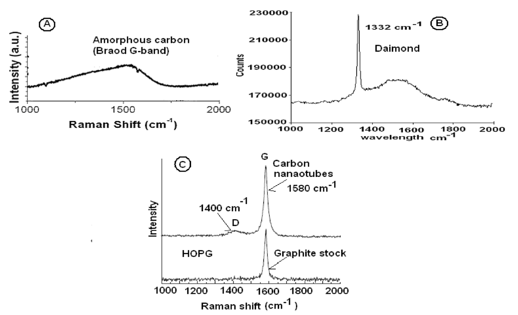
positions of the D-bands and G-bands are shown in Fig. 6; and, for comparison, Raman spectra of amorphous carbon, diamond, graphite, and CNT are shown in Fig. 6.
The Raman peaks at 1580 cm-1 in both samples (i.e. CNT and graphite) are attributed to the tangential stretching G mode. The peak at 1400 cm-1 is attributed to the disorder-in-
duced D mode, which did not occur in the Raman spectrum of the graphite stock. The appearance of a D band is due to defects on the CNT or to amorphous carbon in the product, which shows the graphitization degree of the product. The Raman spectrum of all carbon materials (Fig. 7) shows the presence of G- and D-bands. Their positions are shifted more towards the higher wave number (i.e. more towards the G-band obtained for the highly ordered pyrolytic graphite [HOPG]).
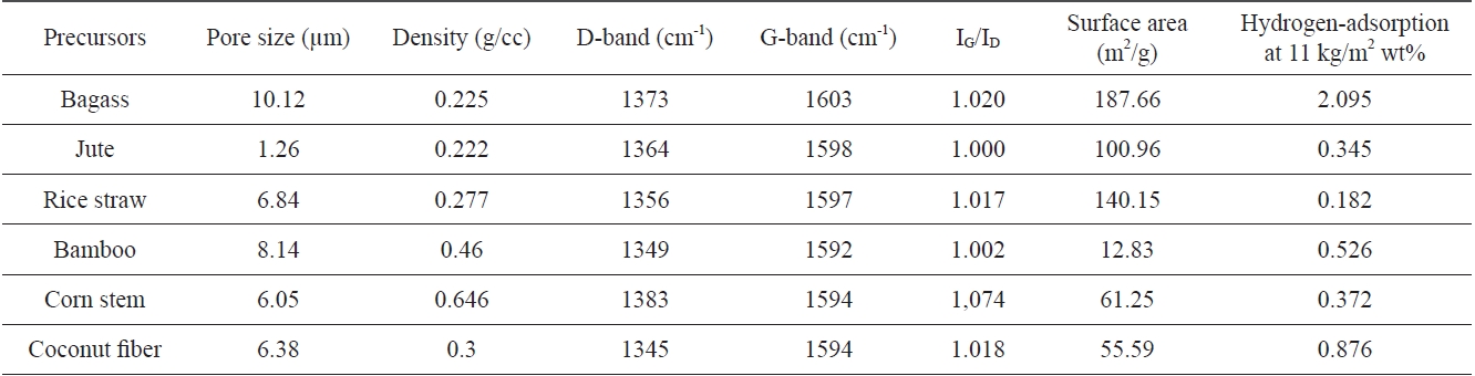
Hydrogen adsorption and various properties of carbon materials prepared from different plant materials
Almost all CNMs showed almost equal intensities of G- and D-bands, with slight variations. Band intensities were in the range of 0.7 to 0.9.
Our findings on the characteristics of CNM prepared from fibrous plant materials show that since these were complex precursors having different types of chemical compounds, the pyrolyzed product yielded lots of impurities along with amorphous carbon, and hence acidic purification was needed. So far as the morphology of the carbon is revealed from the SEM studies, it is considered that the complex morphological nature can be attributed to the nature of the morphology of the precursors. All the carbons had a (002) plane shift towards the lower angle of 26.4°. Raman studies of all CNMs showed the presence of G-and D-bands of almost equal intensity, suggesting the presence of graphitic carbon as well as a disordered graphitic structure.
3.3.1. Hydrogen absorption capacity of carbons synthesized from different precursors
Hydrogen adsorption capacity and various properties of carbon materials prepared from three plant materials, which showed promising results, were compared and are presented in Table 1.
Table 1 shows that carbon materials possessing lesser density, larger surface area, more graphitic structure with less of an sp3 carbon contribution, and having pore sizes of around 10 μm favor hydrogen adsorption. Carbon materials synthesized from bagass meet these requirements more effectively than materials fabricated from other types of carbon material. The second most effective carbon material was that prepared from cotton.
Plant fibers, being rich sources of carbon and having different inherent plant structures, have yielded carbons with different morphologies. Depending on their available surface area and density, they have shown differences in their capacity to adsorb hydrogen gas. These findings on hydrogen adsorption capacity, and an analysis of the morphology of the carbon material synthesized from different plant fibers, open a new possibility of correlating the finer structure of the synthesized carbon and their various applications. Such studies would help in the future in synthesizing desired types of carbon material from waste plant material for use in different applications.

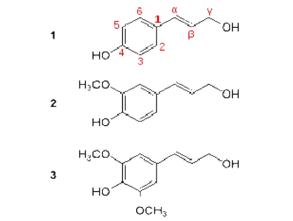
![Molecular structure of LIGNIN having three common mono-lignols [(1) Paracoumaryl alcohol, (2) Coniferyl alcohol and (3) Sinapyl alcohol]](http://oak.go.kr/repository/journal/11279/HGTSB6_2012_v13n3_161_f001.jpg)


![X-ray diffraction of (A) carbon nanotubes (CNTs) showing (002) plane of graphite (Du et al., 2008 and Chen et al., 2005) and (B) carbon nanofibers (CNFs) showing (002) plane of graphite [13].](http://oak.go.kr/repository/journal/11279/HGTSB6_2012_v13n3_161_f006.jpg)

![Raman spectra of (a) amorphous carbon film [Ferrari et al., 2000][14] showing a overlapping with a broad G-band and D-band. (b) Diamond showing a sharp D-band [15] and (c) showing intense G-band and small hump of D-band obtained via CNT and intense peak of G-band for highly ordered pyrolytic graphite (HOPG) [Chen et al., 2005] [12].](http://oak.go.kr/repository/journal/11279/HGTSB6_2012_v13n3_161_f008.jpg)