A carbon nanotube (CNT) refers to a molecule that is shaped like a long tube with hexagonal rings of carbons connected to each other. The CNT has a very high tensile strength of 13-53 GPa and modulus of 1 TPa [1]. It is higher than copper in electrical conductivity and current density and similar to diamond in thermal conductivity [2-4]. The mechanical and electrical properties of CNTs vary depending on the arrangement of hexagonal rings constituting them and the number of walls in them; the properties of individual CNTs are superior to those of commercialized high-performance fibers [5-9]. In order to allow for the use of such outstanding properties in different fields of industry, individual CNTs should be made into fabrics or fibers that are CNT aggregates and that can show their properties as they are. Once fibrous CNT aggregates are fabricated, their superior mechanical, electrical, and thermal properties can be used not only in one-dimensional form, but also, when fabricated into two-dimensional structures like fabrics, in a variety of fields including electrodes, clothing, power generators, and sports equipment. When compared to carbon fibers, which have a density of 1.8 g/cm3, CNT fibers are very light, with a density of 0.2 g/cm3; thus, they can be used efficiently in the field of ultra-lightweight composite materials [10].
Herein, we review the fabrication and applications of CNT fibers with the abovementioned outstanding properties.
Comparisons of strength and electrical conductivity between dry- and wet-fabricated CNT fibers
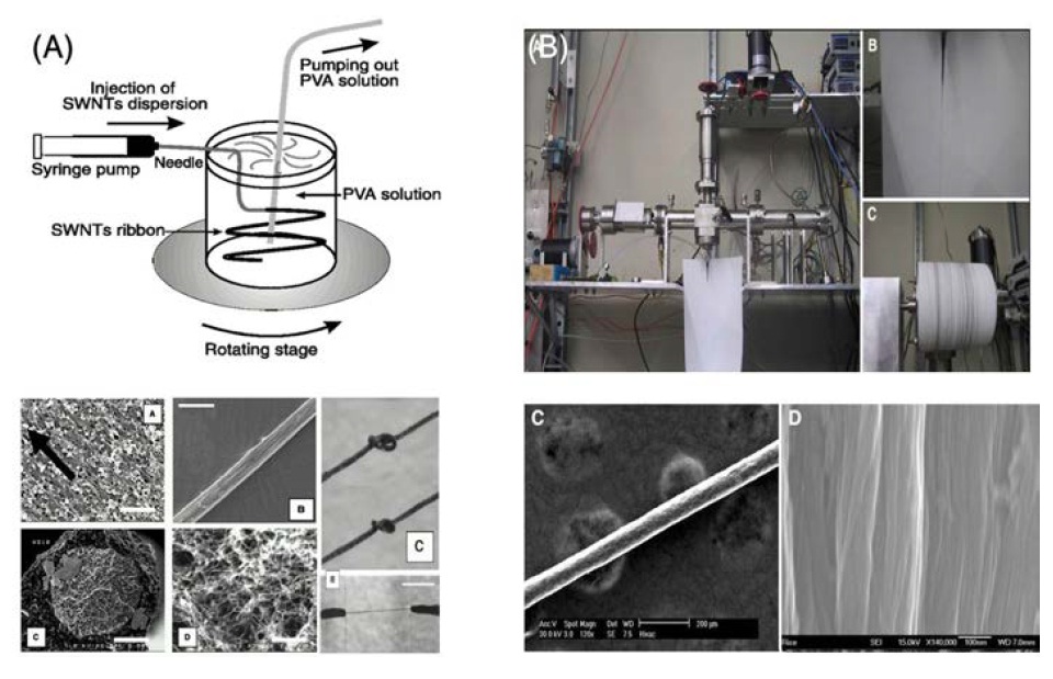
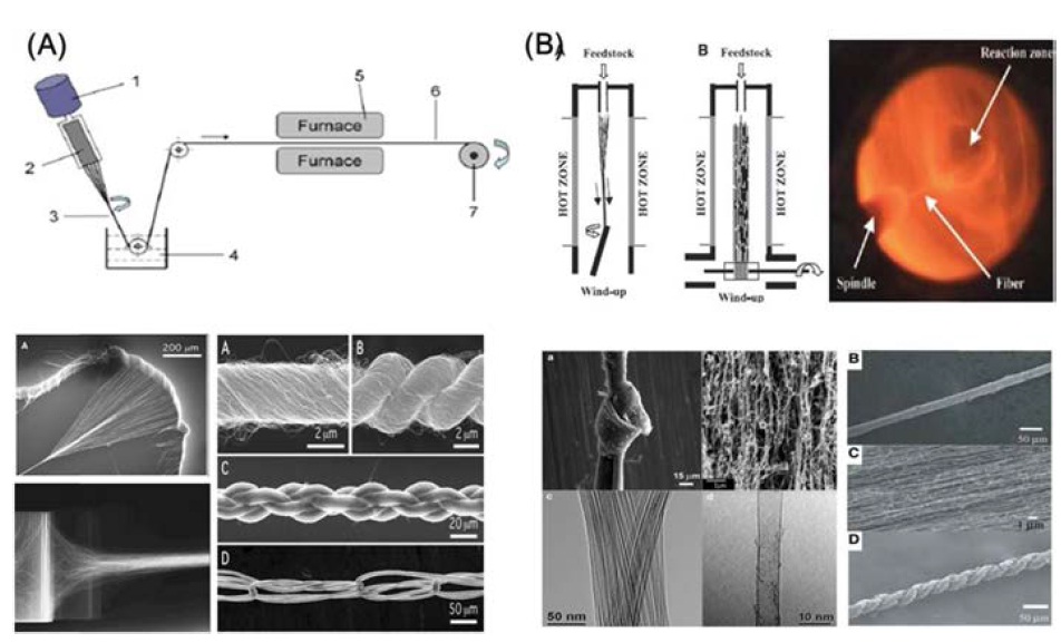
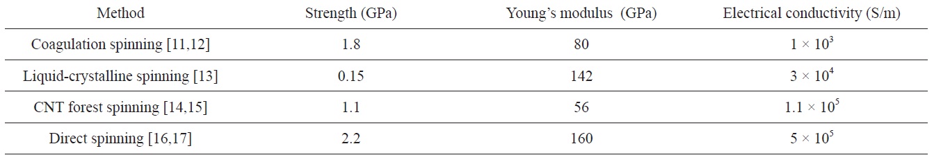
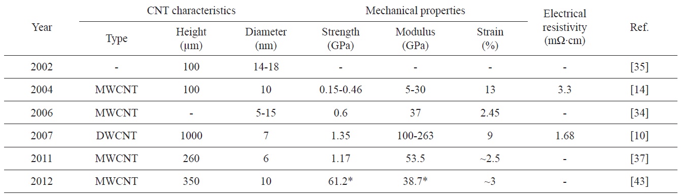
Up to the current moment, four methods of fabricating CNT fibers are known: surfactant-based coagulation spinning [11,12], liquid-crystalline spinning [13], CNT forest spinning [14,15], and direct spinning [16,17]. As shown in Table 1, CNT fibers have the most outstanding properties when fabricated by direct spinning. For surfactant-based coagulation spinning, a CNT dispersion solution is injected into a polymer solution and the dispersant in the dispersion solution is replaced by a polymer after going out to the polymer solution. The polymer serves as a binder for fiber formation (Fig. 1a) [11,12]. Thes fabricated by this method have a CNT content of 60 wt%, a very high level that has never been achieved by other existing composite materials; however, the presence of polymers between CNT particles is evidence that those fibers have failed to overcome the limitations of composite materials. Liquid-crystalline spinning is a fiberization method that uses the nature of the CNT solution to form a liquid crystal under certain conditions (Fig. 1b). This method is advantageous for making highly-orienteds but exhibits a very slow speed of spinning the fibers and leads to difficulty in obtaining liquid crystal phases of CNTs [13]. Moreover, the fibers have poor properties because they are merely the aggregates of CNT particles. The most widely known dry method for fabricatings is to spin from vertically grown CNTs on a wafer (Fig. 2a). Vertically grown CNT aggregates are called forests, carpets, or mats because of their shape. The forest is drawn and twisted for fiber fabrication. This method is not suitable for mass production due to the limited silicon wafer size and discontinuous production process; properties vary depending on where the CNTs are positioned on the wafer [14,15]. Another dry fabrication method, direct spinning (Fig. 2b), uses an injection of a liquid carbon source and catalyst with a carrier gas into a high-temperature electric furnace for CNT synthesis in the furnace and winds ups coming down to the bottom of the furnace for fiber fabrication [16,17]. This method exhibits a spinning rate of 20-30 m/min and is suitable for mass production ofs, making it better than other methods in this regard. The main discussion in this review paper is to focus on the dry fabrication methods: direct spinning and CNT forest spinning.
The term ‘direct spinning’ was used first in 2004 when Professor A. Windle (UK) [16] reported that he had succeeded in fabricating a CNT using a vertical furnace. Since then, direct spinning has been used to refer to similar ways to synthesize
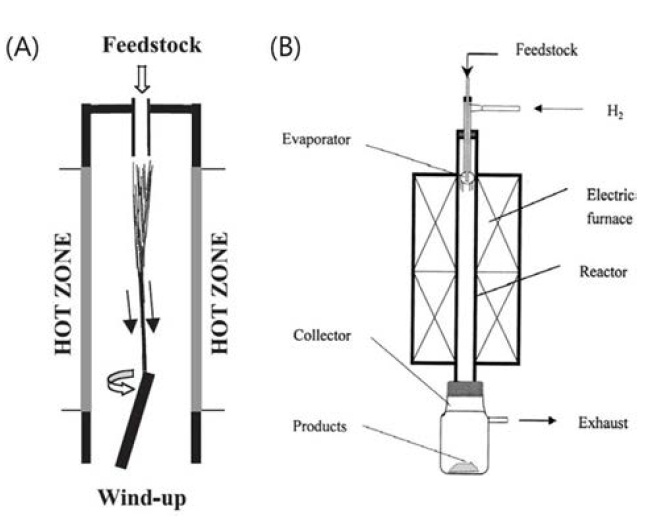
CNTs with a vertical furnace and make them into fibers. The fabrication of vapor-grown carbon fibers (VGCFs), which can be said to be the first method of direct spinning, was reported by Schutzenberger in the 19th century [18]. In 1976, Oberlin et al. [19] reported that they had measured the morphology of VGCFs with a transmission electron microscope (TEM). The carbon filaments that they fabricated are thought to have had CNT structures. In their report, the filaments appearing in a TEM image have tube structures of 2-50 nm in diameter. Therefore, the carbon filaments they discovered are believed to be the first reported CNT filaments [19]. Ci et al. [20,21] reported that they had fabricated carbon nanofibers in a way very similar to the direct spinning method, which uses a vertical furnace for fabrication of CNT fibers (Fig. 3a) [16]. With a system built for the purpose, they succeeded in the fabrication of carbon nanofibers by injecting a gas and
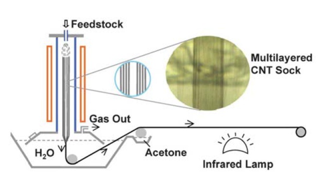
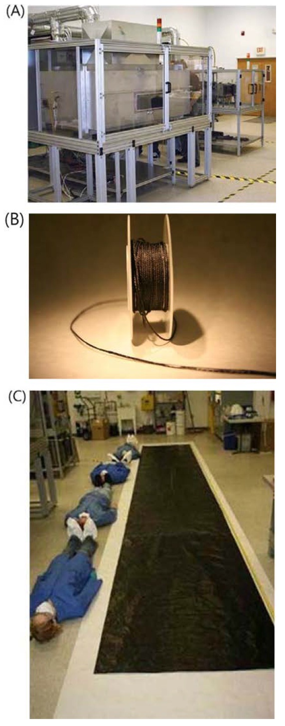
catalyst solution from the top of a vertical furnace (Fig. 3b) [20,21]. Apparatuses and feedstock applicable to direct spinning had been studied by many different researchers prior to Professor A. Windle’s study [16], which has great significance in that such equipment and methods were properly used to synthesize CNTs and fabricate CNT aggregates continuously into fibrous forms at the bottom of the furnace. Professor Y. L. Li (China) [22] reported that CNT fibers could be fabricated with a slightly modified direct spinning system (Fig. 4). Zhong et al. [22] used a water bath installed at the bottom of the furnace to densify CNT fibers and succeeded in increasing the densification rate and the strength of the CNT fibers by introducing a post-treatment process with acetone. In Korea, Lee et al. [23] reported that CNT fibers worked as a good field emitter when they were continuously fabricated using a direct spinning method. Besides these methods, Nanocomp Technologies (USA) fabricated high-strength, high-conductivity CNT fibers and CNT sheets using a horizontal furnace, not a vertical furnace (Fig. 5) [24].
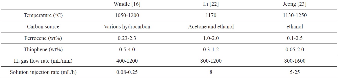
In a study by Li et al. [16], different hydrocarbons such as ethanol, diethylether, polyethylene glycol, 1-propanol, acetone, and ethylformate were used as carbon sources. Ferrocene as a catalyst and thiophene as a promoter were injected into the car-
bon sources from the top of a vertical furnace. Hydrogen was used as a carrier gas and CNT fibers were fabricated in a reactor with a temperature range of 1050-1200℃. They reported that when the flow rate of hydrogen gas increased and the amounts of injected solutions were maintained at a constant level, to the result was a relatively decreased ferrocene concentration and a low frequency of iron-iron collisions; as a result, a smalldiameter iron catalyst was created [16]. This suggests that an increased flow rate of hydrogen gas will induce the synthesis of double-walled CNTs (DWCNTs) or single-walled CNTs (SWCNTs) rather than multi-walled CNTs (MWCNTs) by causing a small-diameter iron catalyst to be formed. On the contrary, if the amounts of injected solutions are increased with the flow rate of hydrogen maintained at a constant level, the result will be an increase in the concentration of the ferrocene and in the frequency of collisions between iron catalysts, thus contributing to the formation of a large-diameter iron catalyst and the production of MWCNTs [25]. Meanwhile, professor Y. L. Li [22] reported that there was a twice or more increase in the yield of CNTs when CNT fibers were fabricated using acetone and ethanol as carbon sources. Jung et al. [26] used ethanol as a carbon source to fabricate CNT fibers in a vertical furnace at 1130- 1250℃. They reported that the number of CNT walls depended on the concentration of ferrocene and the content of thiophene; the crystalline quality of the CNTs was influenced by the injection rates and the temperatures of hydrogen and the solution [26]. In 2011, professor A. Windle [27] reported that a SWCNT with metallic chirality had been synthesized by using gaseous methane as a carbon source and carbon disulfide as a promoter of CNT synthesis (Table 2).
It is known that metal catalysts are mainly used for CNT synthesis and that there are a wide variety of carbon sources available in gaseous or liquid state [28-30]. Hydrocarbons are broken down to carbon and hydrogen by pyrolysis on the surface of a metal catalyst; carbon is dissolved into the metal catalyst. In this stage, if the carbon is diffused and saturated in the metal catalyst, CNTs are formed with the deposition of carbon onto the surface of the catalyst. The carbon diffusion in a metal catalyst is determined by the temperature or the carbon concentration. Finally, if carbon forms a fiber on the back of the metal catalyst and the catalysis is covered by graphite formed on the metal surface, then the catalyst loses its chemical activity and stops growing [31]. For direct spinning, if a synthetic solution consisting of hydrocarbons (i.e., ethanol, acetone, etc.), ferrocene, and thiophene is injected with hydrogen gas from the top of a furnace, ferrocene is broken down to yield iron particles, which will act as a catalyst [16,32]. In addition, the hydrocarbon (i.e., ethanol or acetone, available as a carbon source) is dissociated and CNTs are produced with carbon diffusion into the iron catalyst. Thiophene sulfur is known to promote the diffusion of carbon into the iron catalyst by lowering the melting point of the catalyst [33]. Synthesized CNTs form elastic smoke (sock) in the furnace and are carried down to the bottom of the furnace with non-reactive materials. They are bundled to form CNT fibers at the bottom [21,22,32].
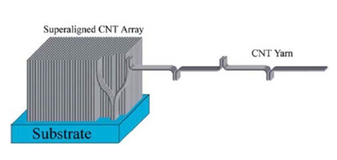
Since direct spinning produces CNT fibers simultaneously with synthesis, the CNT fibers fabricated as such are reported to exhibit better properties than those fabricated by CNT forest spinning. As shown in Fig. 6, when CNT forest spinning is used for fiber fabrication, the CNT ends are connected to each other by van der Waals forces and such connections are released to form a fiber. However, it can’t be said that such a CNT fiber is better in strength than other CNT fibers fabricated by direct spinning, because the force connecting the CNT ends is very weak [10,34]. The direct spinning method, which is used to fabricate CNT fibers by CNT synthesis in a furnace, gives high strength and electrical conductivity to the
[Table 2.] Conditions for the synthesis of CNT fibers upon use of a vertical furnace

Conditions for the synthesis of CNT fibers upon use of a vertical furnace
fibers as CNTs or CNT bundles are intricately connected like a network [32]; this is in contrast to CNT forest spinning, in which CNT fibers are fabricated by forming inter-CNT combinations based on van der Waals forces.
The biggest problem that occurs when fibrous aggregates are created by the dispersion of CNTs in a solution is that CNTs are not fully dispersed. Developed as a solution to the problem, CNT forest spinning involves pulling out CNTs in fibrous form using the interaction of CNTs themselves without the help of any other substances in attaching a number of vertically grown CNTs on a substrate. This spinning method was given its name because it is similar to dragging trees away from a dense forest.
Initially, CNT forest spinning involved drawing approximately 30 cm long CNT fibers from a vertically grown CNT forest [35]. After that, CNT fibers of more than 460 MPa in strength were fabricated by giving a twist to the CNT fibers being spun from the CNT forest. When twisting is applied to a CNT fiber, as shown in Fig. 2a, CNT bundles are tilted at a certain angle to the axial direction of the fiber and more effective load transfer is achieved with an increase in the interaction between CNTs [14]. Subsequently, transparent and well-aligned sheet-like CNT fibers were fabricated [36], and with the fabrication of a 1-mm-long CNT forest the tensile strength and modulus were improved to 3.3 GPa and 263 GPa, respectively [34]. The principle at work here is similar to the principle that the longer the length of monofilaments constituting a cotton fiber, the more the friction increases with the interaction between monofilaments and the more the
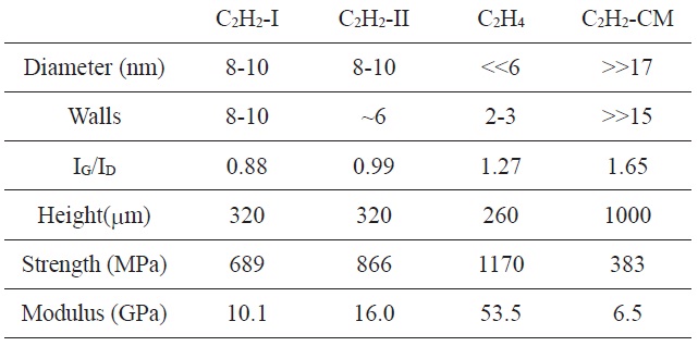
Tube diameter, number of walls, IG/ID ratio of Raman intensities, array height, and mechanical properties of the C2H2-I, C2H2-II, C2H4, and C2H2-CM fibers [37]
mechanical properties improve. For defective parts in which the ends of individual CNTs are separated from each other. thus rendering the fiber as a whole unconnected, the properties can be considered to have improved because the longer the length of the individual CNTs, the smaller space they occupy in the entire fiber [10,34]. A few studies were conducted in terms of how the properties of CNT fibers change according to the nanotube’s structure, purity, density, and degrees of orientation and straightening [15,34,37-42]. In a study that attempted to fabricate a spinnable CNT forest under different CNT growth conditions, thin and long CNT fibers with a small number of nanotube walls and outstanding mechanical properties were fabricated using C2H2 as a carbon source, as shown in Table 3 [37]. In addition, for the improvement of properties by structural densification, a fibrous CNT aggregate was fabricated by passing a CNT film through a volatile solvent like acetone. In 2006, a 10 cm-wide film was shrunk with a yarn of 30 μm in diameter to achieve a strength of 600 MPa [34,38]; in 2010, as shown in Fig. 2a, a circularsectional fiber with a tensile strength of 1 GPa was fabricated from a CNT array by giving a twist to the array and then immersing it in a volatile solvent [15]. A recently proposed method for CNT fiber production is to produce a CNT fiber from a CNT forest without giving the fiber a twist. CNTs in a twisted fiber are densely packed along the axial direction of the fiber due to strong compression by the twist, while outside the fiber they have a constant angle to the axial direction and are cross-aligned according to the twist angle. These CNTs are not in line-contact but in point-contact with one
[Table 4.] CNT characteristics and CNT fiber properties (*N/tex)
CNT characteristics and CNT fiber properties (*N/tex)
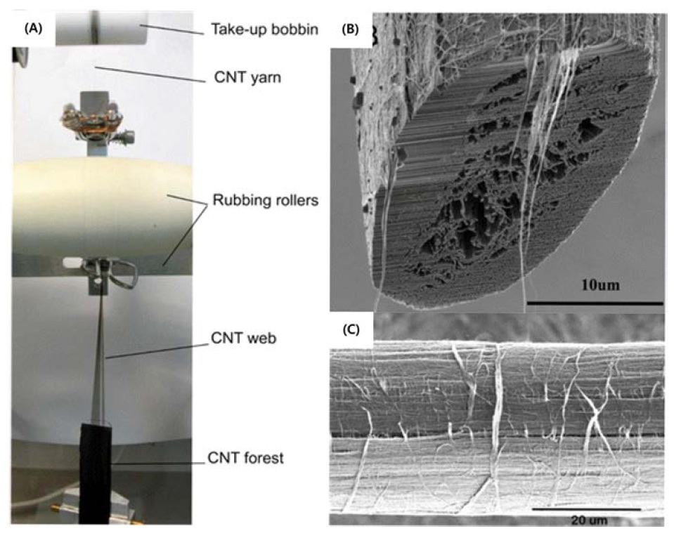
another, so the interactions between them are not sufficient. For that reason, in order for the inter-CNT interactions to be maximized by line contact between CNTs, Miao et al. [43] fabricated a densified CNT fiber by passing CNT webs between rotating and reciprocating pad-type rollers, as shown in Fig. 7. This twistless CNT fiber showed an 87% increase in modulus compared to that of twisted ones (Table 4) [43].
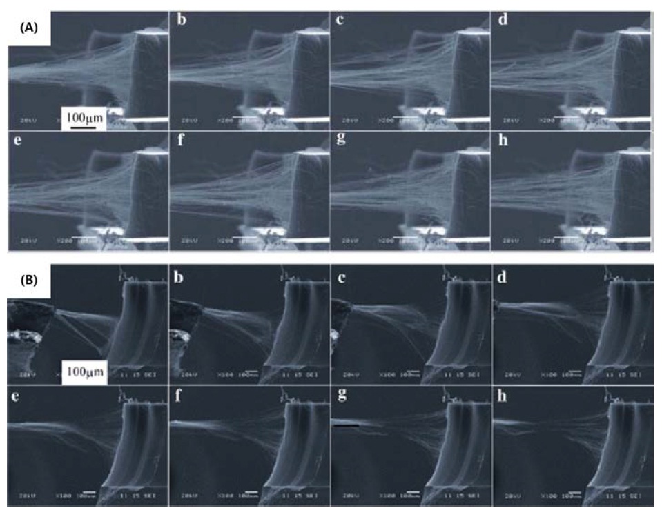
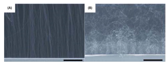
The basic principle of CNT forest spinning is that when CNTs are pulled out of the forest, other neighboring CNTs are continuously released and spun. This continuous spinning of fibrous CNT aggregates is divided into two main mechanisms: One is that CNTs grown vertically on a substrate are fiberized by the medium of van der Waals forces. The nanotubes can be produced in a continuous way without any interruption because of the parts intertwined, not straightly aligned, on the top and bottom of the CNT forest, as shown in Fig. 2a [15]. For better-quality CNT fibers, the CNT forest should be vertically well-grown and have no foreign matter on the surface [34]. The other spinning mechanism is one in which CNT fibers are spun out in a continuous manner with fine CNT bundles connecting between other bundles of CNTs, as shown in Fig. 8a. This is similar to the principle that when you tear off string cheese, it splits with the formation of web-like stands [44].
CNT forest spinning allows CNT fibers to be spun out of a CNT forest after CNTs are grown on a substrate by chemical vapor deposition; therefore the type, length, diameter, and straightening degree of each CNT can be independently controlled during the fabrication of the CNT forest. Such
controllability makes it easy to find changes in the structures and properties of CNT fibers, but there is a limitation on the length of CNT fibers available in any process because the fibers are be batch-produced. The size of the substrate cannot be expanded to infinity, so the number of CNTs that can be grown is limited. Another problem is a poor reproducibility of CNT fiber fabrication. It is already a common method to grow a CNT forest, but there is still a limit to the capability of pulling out CNT films, evenly from a fabricated CNT forest, at all times. This is probably because the factors determining the spinnability of CNT fibers have not been obviously identified.
However, Iijima et al. [45] found one cause of such unspinnability in an area in which CNTs are in contact with the substrate in a CNT forest. The continuously spinnable CNT forest shown in Fig. 8a has CNTs densely grown in line at its bottom, as shown in Fig. 9a; thus, the junctions between CNTs are considered good enough to draw them continuously. However, as can be seen in Fig. 8b, the unspinnable forest does not allow the continuous spinning of CNT fibers because the CNT bundles drawn from the bottom are not sufficiently bound. Fig. 9b accounts for the low binding force at the bottom of the unspinnable forest. The reason for such a low binding force is that the iron catalyst underlying the growth of CNTs loses its activity as it becomes surrounded by amorphous carbons generated in a furnace. As a consequence, the loss or decrease in iron catalyst activity decreases the number of growing CNTs and makes them far from each other to the extent that van der Waals forces can’t work between them. Moreover, the produced CNTs are hard to bind at the bottom of the forest because they are not straight but curved or bent. This makes the spinning of CNT fibers impossible.
2.3.1. Improvement of mechanical properties
CNT fibers are fibrous aggregates of individual CNTs joined together by van der Waals forces. The van der Waals force is an attractive force that works between neighboring molecules. As the distance between CNTs increases, the attractive force becomes weak and interaction between CNTs becomes unlikely to occur. In contrast, when CNTs are close to one another and in broad contact, the interaction between CNTs is more likely to take place and thus their properties improve. Accordingly, the mechanical properties of CNT fibers can be improved by decreasing the distance between CNTs and increasing contract between them through the densification of CNT fibers without using any materials other than CNTs. A volatile solvent (e.g., ethanol or acetone) applied to CNT fibers works to densify the fibers by getting the solvent’s capillary force to attract individual CNTs during its evaporation [15,46]. The twisting of CNT fibers can help reduce the distance between individual CNTs and increase the area of contact between them. As shown in Fig. 10,
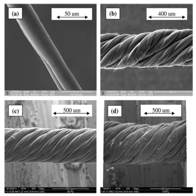
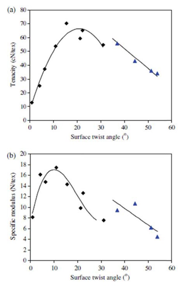
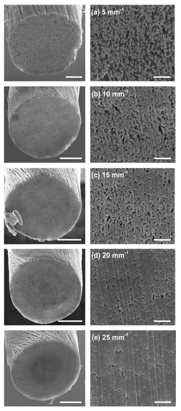
CNT fibers can be produced to have different structures and properties by making changes in the number of fiber strands and the number of twists per unit length [14,47]. The number of twists should be moderate because too many twists may deteriorate the properties of the fibers [14]. Miao et al. [48] argued that as shown Fig. 11, CNT fibers showed optimal strength and hardness at twist angles of 20° and 10°, respectively. As shown in Fig. 12, when a CNT fiber is moderately twisted, the density of
CNTs increases evenly across the fiber as the number of twists increases. In contrast, if a CNT fiber is excessively twisted, CNTs in its center are densely packed along the axial direction under considerable compressive force due to such twists, while outside CNTs exist in a somewhat loose state and are greatly tilted from the axial direction. This causes a significant decrease in the strength of the CNT fiber [49].
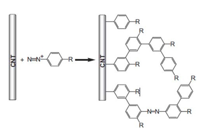
Another method for improving the mechanical properties of CNT fibers is to induce stronger covalent bonding instead of relying on van der Waals forces. First, chemical bonding between CNTs can be caused to take place using a functional group introduced by chemical reactions for CNT surface treatment. Cai et al. [50] applied a diazonium salt solution with a different pH value both during and after the spinning of a CNT fiber and introduced a functional group onto the CNT surface after the production of the CNT fiber, as shown in Fig. 13. As the ph-controlled reaction solution penetrated evenly into the twisted CNT fiber, the surface modification of CNTs occurred in all parts of the fiber and, as a result, this process increased both the strength and modulus of the CNT fiber.
The properties of CNT fibers can be also enhanced by forming strong chemical bonds between CNTs through gamma or ultraviolet irradiation [51]. This method causes the functional groups of individual CNTs to react to one another after the introduction of each functional group (e.g., carboxylic acid) onto the CNT surface. The more the fiber is twisted (5 < 25 turns/mm), the greater the effect of the gamma irradiation on the fiber’s strength. This is probably because a larger number of twists increase the inter-CNT contact and, accordingly, maximize the effect of property improvement by gamma irradiation [52].
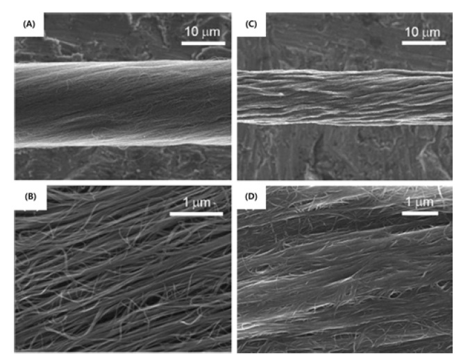
When fibrous CNT composite materials are made by impregnating CNT fibers with a polymer solution in an attempt to improve the fibers’ mechanical properties, the polymer works to decrease the electrical conductivity of the materials [14]. In order to solve this problem, Liu et al. [53] fabricated a high-strength and high-conductivity fibrous CNT composite material. In that study, they spun CNT fibers continuously from a super-aligned CNT forest and used them as a conductive frame. As shown in Fig. 14, the fibers were made into composite fibers by dehydration after immersion in a polyvinyl alcohol (PVA)/dimethyl sulfoxide (DMSO) solution. PVA, which is a flexible and highly-adhesive polymer, was used to increase the strength of CNT fibers by get-
ting in between them. The strength of the fabricated composite fibers increased four times from 0.5 GPa to 2.0 GPa; their modulus increased up to 120 GPa. They showed a high electrical conductivity of 9.20 × 10⁴ S/m, compared to that of CNT fibers treated with nitric acid or coated with gold nanoparticles. Besides, the composite fibers were found to be flexible, lightweight, scratchresistant, and stable in humid settings.
2.3.2. Improvement of electrical properties
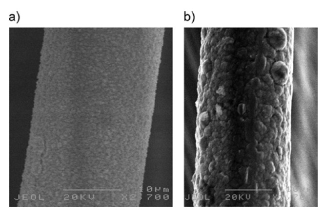
The electrical conductivity of CNT fibers composed of MWCNTs is very low compared to that of flawless individual CNTs. The reason for such low conductivity is that the presence of amorphous carbon and other impurities in CNTs prevents the flow of electrons [54-57]. Untreated pure CNT fibers have electrical properties similar to those of semiconductors and show an electrical conductivity of 5-6 × 10² S/cm at room temperature. One of the methods of improving the electrical properties of CNT fibers is to create a path through which electrons flow on the CNT fibers [9,58]. Randeniya et al. [59] succeeded in improving the electrical properties of CNT fibers via the synthesis of a metal-CNT composite fiber in a process called self-fuelled electrodeposition. Produced in such a way, the composite fibers were designed to serve as external circuits through which electrons could travel with a metal reductant deposited on the CNT surface, as shown in Fig. 15. The electrical conductivity of Cu-CNT and Au-CNT composite fibers improved to almost 2-3 × 10⁵ S/cm, similar to that of metals; however, their tensile strength was found to decrease by 30-50%.
Before the invention of pure CNT fibers, CNTs had been actively studied for use in fillers of composite fibers. However, it was hard for CNT composite fibers to express the unique quali-
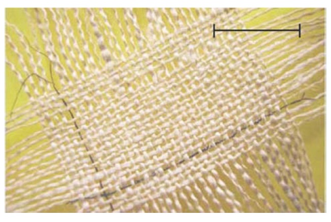
ties of CNTs due to the difficulty in CNT dispersions and the problem of low contents. Accordingly, attempts to fabricate fibers of pure CNTs only have been made in many different ways. In 2003 before pure CNT fibers were first reported, Dalton et al. [60] reported a CNT/PVA composite fiber with a CNT content of as much as 60 wt%. This composite fiber was innovative enough to exhibit the potential applicability of CNT fibers. They also fabricated a super capacitor by inserting the composite fiber into a woven fabric. The CNT composite fiber reached 0.6 W h/kg at a capacitance of 5 F/g and an energy-storage density of 1 V (Fig. 16) [60]. Subsequently, Zhang et al. [14] succeeded in spinning CNT fibers from CNT forests grown on wafers and reported that they could be used as artificial-muscle actuators or for radio or microwave absorption, electrostatic discharge protection, textile heating, or electronic-device wiring.
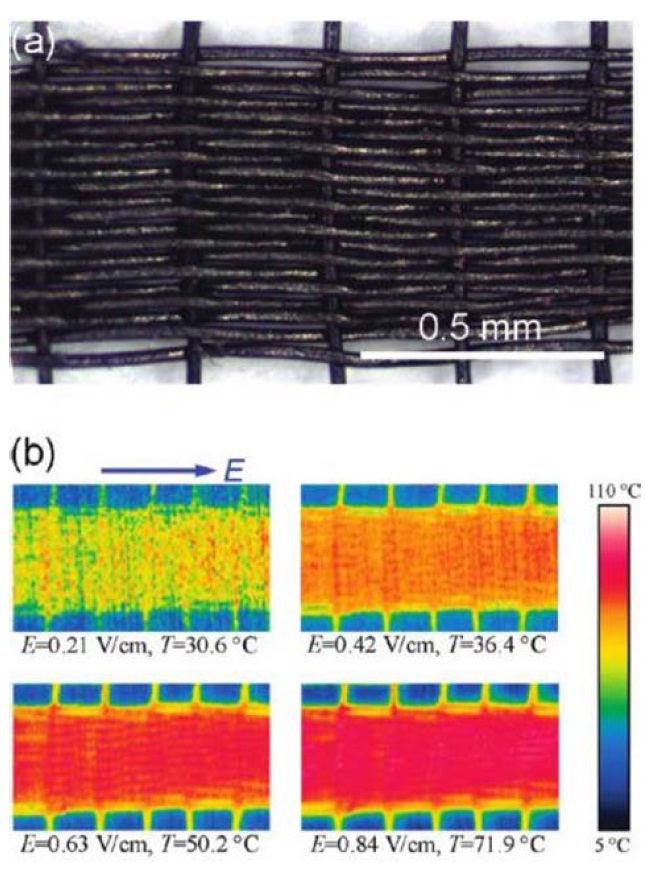
If pure CNT fibers are transformed into fabric structures in an applicable range, their applications will be further expanded. Such a case was reported in 2010 by Liu et al. [53], who suggested the possibility that CNT fibers could be used as heating fabrics by making them into the form of fabrics. They raised the temperature up to 70℃ by applying an electric field of 0.84 V/cm onto a fabric made of CNT fibers (Fig. 17). This heating feature can be also used in flexible heaters, bullet-proof vests, and spacesuits. Fabrics made with CNTs, known as ideal blackbodies, can ab-
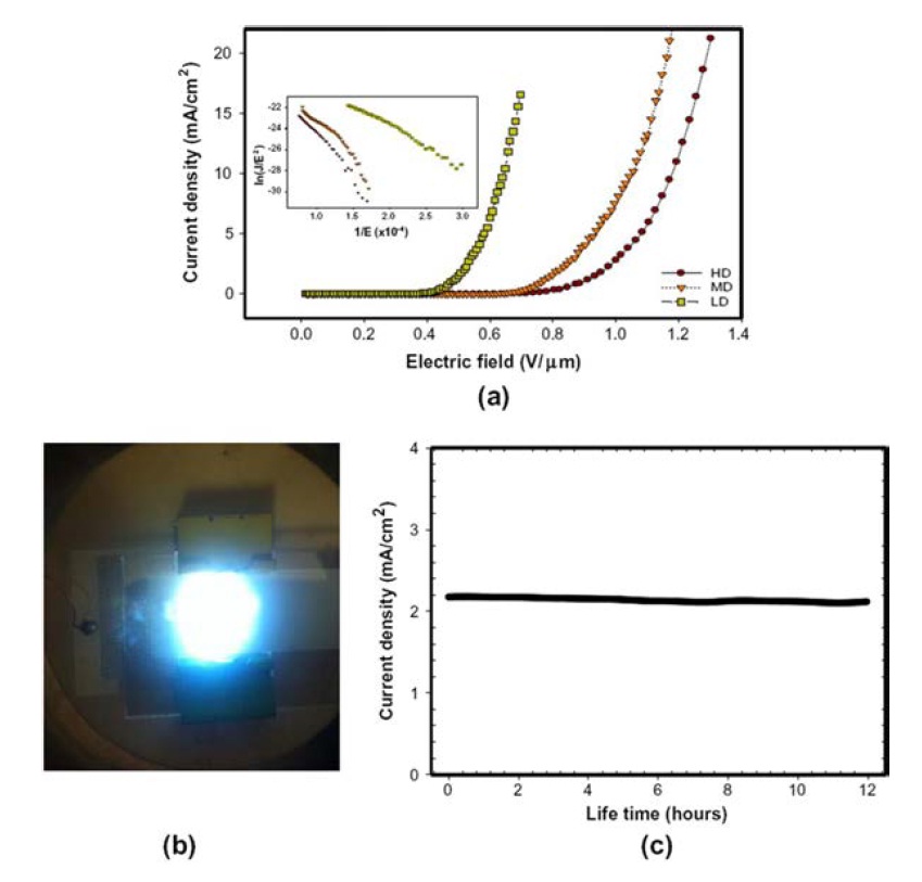
sorb electromagnetic waves and can therefore be used for radiation suits [61]. Mizuno et al. [61] argued that CNTs should be vertically aligned to maximize the effects of radiation protection and display better performance as blackbodies. However, it is difficult to align the particle-type CNTs vertically on the fabric surface; it is also not easy to mass-produce such CNTs. In order to solve those problems, Lee et al. [23] aligned CNT fibers vertically by fabricating a velvet woven fabric; they then studied the exceptional performance of the CNTs as field effect transistors using CNT fibers. The results of their study indicate that under very low voltage conditions, CNT velvet fabrics not only emit many electrons but also provide high stability (Fig. 18).
Park et al. [62] demonstrated that fabrics made using CNT fibers can be used as large-area sensors. They found that the capacitance of fabrics made of CNT fibers varied depending on the distance between two fabrics when they were touched and designed a pressure sensor based on the principle. CNT fibers are essential for ‘smart’ clothing. Since conductive polymers are difficult to fabricate in fibrous form, smart textile products have been being manufactured using micro-sized copper fibers. However, metal fibers are heavy and susceptible to water and can be easily broken due to poor elasticity when elongated for better flexibility. That’s why the commercialization of CNT fabrics is being retarded, despite a large and diverse demand for smart clothing. It can be therefore said that CNT fibers which are similar dynamics to other fibers manufactured for clothing are very promising materials in
the smart clothing industry. CNT fibers provide a high strength of up to 0.4 N/tex without any special post-treatment; they have a breaking elongation of more than 10%.
The outstanding electrical properties of CNT fibers have led to discussion of their high potential as power cables. One advantage of CNT fibers as power cables light is that they weigh very little. The density of CNT fibers is approximately 0.2 g/cm3 [61], only one-forty fifth of the copper density being 8.96 g/cm3. The importance of such lightness and low density can be realized when the weight of copper used in Boeing 747 airplanes is taken into account. The copper used in a Boeing 747 airplane is 217 km long and weighs 1800 kg [63]. The replacement of copper with CNT fibers could reduce the plane weight by approximately 1760 kg. In order for this to come true, it must not only be possible to mass-produce CNT fibers, but the produced fibers should be made capable of providing a conductivity comparable to that of copper. Recent studies have reported that CNT fibers doped with iodine could show a copper-like conductivity [64]. These studies indicate that treating CNT fibers with iodine vapor can increase their conductivity up to 107 S/m. In view of such findings, copper-replacing CNT fibers are expected to be commercially available in the near future, and the ripple effects of such commercialization will be unimaginably great.
The outstanding dynamic properties of CNT fibers are highly recognized for their potential, especially in the fields of structures and bulletproof materials. For example, an Italian research team announced that if CNTs were applied to a suspension bridge, the length of its main span could be innovatively extended [65]. However, for the present, though they are ideal materials, it is difficult to apply CNT fibers because they have internal defects. Theoretically, a space elevator requires a strength of 100 GPa and CNT bundles 100 000 km long, whereas suspension bridge cables are only required to meet a length of 10 km and a strength of 10 GPa. The research team showed that even defective CNT bundles could increase the current limit of such a main span by more than three times. However, in order for CNT fibers to be used as suspension bridge cables, their production cost should be reduced to as low as 10% of the current level. Further, National Aeronautics and Space Administration scientists suggested the availability of CNT fibers as space elevator cables. It is said that if such space elevators were actually made available, transportation costs would be reduced to 20%, compared to the price of space shuttles [66]. In addition, CNT fibers are also drawing attention as materials for body armor. CNTs can absorb high kinetic energy because they are strong, lightweight, and highly elastic. A research team at the University of Sydney, Australia reported that CNTs were strong enough to withstand repeated impacts. The team calculated that a live bullet of 320 J would bounce off a 600 μ m-thick body armor made of six layers of 100 μm-thick CNT fibers [67]. Body armors made of CNT fibers can diffuse a bullet’s impact over a wider area, compared to the case of existing materials made of super-strong fibers like Kevlar, which prevent wounds such as severe bruises and damage to organs. Such highly conductive, strong and lightweight CNT fibers have an almost infinite range of applications. Particularly because CNT fibers are much lighter than metals, they are expected to emerge as a key material in the aviation, automobile, energy, sports, medical, and munitions industries in the near future. In this sense, doping processes for the mass production of CNT fibers and the improvement of their conductivity should be developed and made commercially available.
Since the successful fabrication of CNT composite fibers with a SWCNT/PVA solution in 2000, CNT fibers have been manufactured by many different methods for the last decade, including the fabrication of CNT-only fibers from a CNT forest in 2002 and the continuous production of fibrous CNTs in a hightemperature vertical electric furnace in 2004. In addition, diverse efforts have been made to improve the production processes of CNT fibers and to develop their post-treatment processes so that the exceptional mechanical, electrical, and thermal properties of individual CNTs can be incorporated into fibrous aggregates of CNTs. Many different methods have already been developed for the continuous production of CNT fibers, but CNT general-purpose use is limited because these fibers have failed to overcome the problem of low strength. CNT fibers have a sufficiently good ratio of strength to weight due to their low density, but if they are to be used as composite materials for structures, they should achieve a degree of strength comparable to that of super-strong fibers or individual CNTs. Further, future studies need to focus on developing mass-production technologies for CNT fibers as well as on improving the physical properties of CNT fibers.


![(a) Surfactant-based coagulation spinning [11] and (b) liquid-crystalline spinning [13] for wet fabrication of carbon nanotube fibers.](http://oak.go.kr/repository/journal/11273/HGTSB6_2012_v13n4_191_f001.jpg)
![(a) Carbon nanotube (CNT) forest spinning [14,15] and (b) direct spinning [16,17] for dry fabrication of CNT fibers.](http://oak.go.kr/repository/journal/11273/HGTSB6_2012_v13n4_191_f002.jpg)
![(a) A schematic diagram of direct spinning introduced in 2004 by Prof. A. Windle. [16] of the University of Cambridge; and (b) a mimetic diagram of the equipment used in 2000 by Ci et al. [21] of Tsinghua University for fabrication of carbon nanofiber.](http://oak.go.kr/repository/journal/11273/HGTSB6_2012_v13n4_191_f003.jpg)
![A diagram of the equipment introduced by Prof. Y. L. Li [22] in 2009. A water bath is used to densify carbon nanotubes (CNTs).](http://oak.go.kr/repository/journal/11273/HGTSB6_2012_v13n4_191_f004.jpg)
![(a) Nanocomp Technologies’ horizontal furnace, (b) fabricated carbon nanotube (CNT) fiber and (c) CNT sheet [24].](http://oak.go.kr/repository/journal/11273/HGTSB6_2012_v13n4_191_f005.jpg)
![A carbon nanotube (CNT) forest spinning model in which CNTs are released in a continuous manner [34].](http://oak.go.kr/repository/journal/11273/HGTSB6_2012_v13n4_191_f006.jpg)
![Tube diameter, number of walls, IG/ID ratio of Raman intensities, array height, and mechanical properties of the C2H2-I, C2H2-II, C2H4, and C2H2-CM fibers [37]](http://oak.go.kr/repository/journal/11273/HGTSB6_2012_v13n4_191_T003.jpg)
![(a) Machine setup for the production of a twistless carbon nanotube (CNT) yarn by rubbing densification. scanning electron microscope images of rub-densified carbon nanotube yarn (b) cross-section and (c) surface [43].](http://oak.go.kr/repository/journal/11273/HGTSB6_2012_v13n4_191_f007.jpg)

![Scanning electron microscope images of (a) continuous spinning of carbon nanotube (CNT) fiber from spinnable CNT forest, (b) spinning of CNT fiber from unspinnable CNT forest [45].](http://oak.go.kr/repository/journal/11273/HGTSB6_2012_v13n4_191_f008.jpg)
![Scanning electron microscope images at root part of (a) spinnable, (b) unspinnable carbon nanotube forest. Scale bar is 1 μm [45].](http://oak.go.kr/repository/journal/11273/HGTSB6_2012_v13n4_191_f009.jpg)
![Scanning electron microscope images of carbon nanotube wires: (a) 1-yarn, (b) 30-yarn, (c) 60-yarn, and (d) 100-yarn [47].](http://oak.go.kr/repository/journal/11273/HGTSB6_2012_v13n4_191_f010.jpg)
![Relationship between carbon nanotube yarn surface twist angle and specific tensile properties [48].](http://oak.go.kr/repository/journal/11273/HGTSB6_2012_v13n4_191_f011.jpg)
![Scanning electron microscope images of focused ion beam sections milled through carbon nanotube yarns with as spun twist densities of (a) 5 mm-1 (b) 10 mm-1 (c) 15 mm-1 (d) 20 mm-1 and (e) 25 mm-1. The left image shows the whole cross-section (scale bar represents 5 μm) while the right image is a higher resolution image taken at the yarn center (scale bar represents 500 nm) [49].](http://oak.go.kr/repository/journal/11273/HGTSB6_2012_v13n4_191_f012.jpg)
![Sidewall modification of carbon nanotubes (CNTs) with an aryldiazonium salt; here R can be any of a large number of moieties including halogen, NO2, COOH, NH2, and alkyl groups [50].](http://oak.go.kr/repository/journal/11273/HGTSB6_2012_v13n4_191_f013.jpg)
![Scanning electron microscope images of yarns. (a, b) SACNT yarn made by the simple twisting method. It can be seen that there are many large intertube spaces. (c, d) SACNT/PVA yarn made from 5 wt% polyvinyl alcohol (PVA)/dimethyl sulfoxide (DMSO) solution. Its intertube space is filled by PVA; its diameter is further reduced compared with that of the twisted and shrunken (by DMSO) yarn [53].](http://oak.go.kr/repository/journal/11273/HGTSB6_2012_v13n4_191_f014.jpg)
![Scanning electron microscope images for metal-carbon nanotube (CNT) yarns: (a) Au?CNT, (b) Cu?CNT [59].](http://oak.go.kr/repository/journal/11273/HGTSB6_2012_v13n4_191_f015.jpg)
![A woven fabric containing two nanotube-fiber supercapacitors (scale bar, 1 cm) [60].](http://oak.go.kr/repository/journal/11273/HGTSB6_2012_v13n4_191_f016.jpg)
![Conductive fabric woven using carbon nanotube (CNT) yarns. (a) Optical image of a woven fabric consisting of CNT yarn. (b) Photos of temperature distribution of the woven fabric under different voltages [53].](http://oak.go.kr/repository/journal/11273/HGTSB6_2012_v13n4_191_f017.jpg)
![(a) Current density?electric field (J?E) curve for the carpet emitters. The inset shows the F?N plots. (b) Luminescence of the velvet emitter. (c) The emission current stability of the velvet emitter [23].](http://oak.go.kr/repository/journal/11273/HGTSB6_2012_v13n4_191_f018.jpg)