Carbon nanotube (CNT) mats are typically fabricated by vacuum filtration of a suspension of randomly dispersed CNTs and are used in various applications such as electrodes [1], gas separators [2], actuators [3], sensors [4], etc. [5]. Since the CNTs in the CNT mat composite are contacted physically, a highly conductive composite can be prepared by using CNT mat fillers. Numerous studies on CNT mat fabrication have been conducted using various processes such as through-thickness infiltration [6,7], intercalation [8,9], electro-spinning [10], hot compression [11], etc., as well as various polymer resins, i.e., epoxy [6,12], polycarbonate [7,13], polyvinyl alcohol, polystyrene [8,9], and polyether-ether-ketone [10]. The electrical conductivity of CNT mat composites depends on the impregnating degree of the polymer resin used, the quality of the CNT mat used, the content of CNT mat in the CNT mat composite, and the interface property between the CNT and the polymer resin [14].
Thermoset CNT mat composites prepared with epoxy resin of low viscosity are generally used in practical applications, because processing problems arise in the fabrication of CNT mat composites due to the nanostructure and properties of the mat. The heat resistance and mechanical properties of thermoset composites are excellent but they have some weaknesses such as difficulties in fabricating complex products, low productivity caused by the curing process, and non-recyclability of the products. Easily and quickly producible and recyclable thermoplastic CNT mat composites can be fabricated by using injection molding and extrusion. However, the content of CNT in the CNT mat composite is limited due to the low processability and high viscosity of the thermoplastic resins. In this study, a fabrication method to improve the processability of thermoplastic CNT mat composites was investigated by using
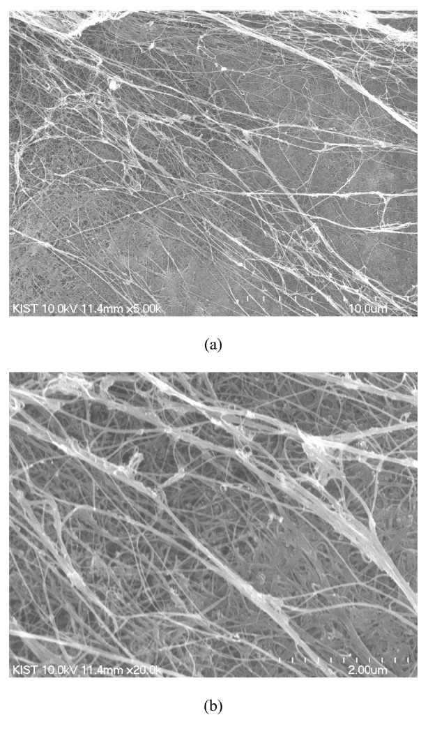
In order to prepare a thermoplastic CNT mat polymer composite with improved electrical conductivity, CNT mat (Nanocomp Technologies Inc., Merrimack, NH, USA) and cyclic butylene terephthalate (CBT, CBT 160, Cyclics Co., Schenectady, NY, USA) were used as an electrically conductive filler and polymer matrix, respectively. For producing the CNT mat shown in Fig. 1, individual multi-walled CNTs (MWCNTs) with lengths of approximately 1 mm were grown by a typical chemical vapor deposition (CVD) method. The grown MWCNTs were collected by a rolling conveyor system and the loosely collected MWCNTs were pressed into a dense mat-like structure [15]. The thickness of the CNT mat was about 12 microns, its density was about 0.25 g/cc, and its free volume fraction was about 86% [16]. The large free volume fraction leads to good wetting of the CNT mat with the polymer matrix. The used CBT 160 resin is a mixture of CBT powder and polymerization catalyst. The number of butyl groups in the CBT oligomer mixture varies from two to seven, resulting in a melting range from 130 to 160℃. CBT 160 resin was dried overnight at 110℃ in order to remove residual moisture, which could interfere with the polymerization reaction [17].
The thermoplastic CNT mat composites were prepared by the following sequence. First, CBT 160 powder was scattered on a steel mold with a fixed quantity. Second, the CNT mat was laid on the scattered CBT 160 powder. Third, a fixed quantity of CBT 160 powder was scattered on the CNT mat. Lastly, the stacked materials were compressed by a heating press (D3P-20J, Dae Heung Science, Inchon, Korea). Thermoplastic CNT mat composites were prepared with respect to compression pressure in order to investigate the electrical conductivity of the composites. The applied processing conditions are summarized in Table 1 and the applied compression temperature and time were 250℃ and 2 min, respectively.
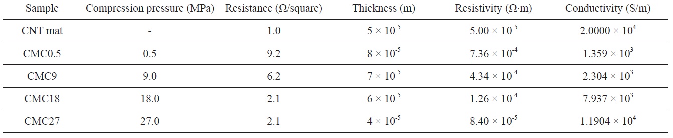
Sample preparation, applied compression pressure, and resistance, resistivity, and electrical conductivity of CNT mat composites
The electrical conductivity of the CNT mat composites was measured by the four-probe method according to ASTM D 257 (FPP-RS8, DASOL ENG, Korea) under ambient conditions. When applying a voltage drop of 500 V between the center and the sample boundary, the resistivity of sample was obtained by measuring the output current. Electrical resistivity is calculated by using the following equation [18]:
where ER is the electrical resistivity, ΔV is the voltage drop over a distance of 6 mm,
The morphology of the surface of the CNT mat composites was observed with a field emission scanning electron microscope (FE-SEM, Hitachi S-4700, Hitachi High Technologies Corp., Japan). The surface of the composites was coated with platinum under vacuum for 200 s by using a sputter coating machine (Ion Sputter E-1030, Hitachi High Technologies Corp., Japan) and then SEM observation was performed at 15.0 kV.
The weight fraction of CNT mat in the CNT mat composites was determined by using a thermo gravimetric analyzer (TGA, Q50, TA Instrument, USA) under a nitrogen atmosphere over a temperature range from 40 to 900℃ at a heating rate of 10℃/min.
The electrical conductivity of the CNT mat composites is listed in Table 1. Since the electrical conductivity measured by the four-probe method mainly depends on the resistance and thickness of a sample, the resistance and thickness of the CNT mat composites are also summarized in Table 1. The electrical conductivity was improved with increasing compression pressure and a relatively large improvement was observed for the CNT mat composites prepared under low compression pressures. As shown in Table 1, the large improvement was due to the significant reduction of resistance of the CNT mat composites prepared under compression pressures of 0.5, 9, and 18 MPa. On the other hand, relatively small improvement was found for the CNT mat composites prepared under high compression pressure. The reduced improvement was due to the decrease of the thickness of the CNT mat composites prepared under compression pressures of 18 and 27 MPa.
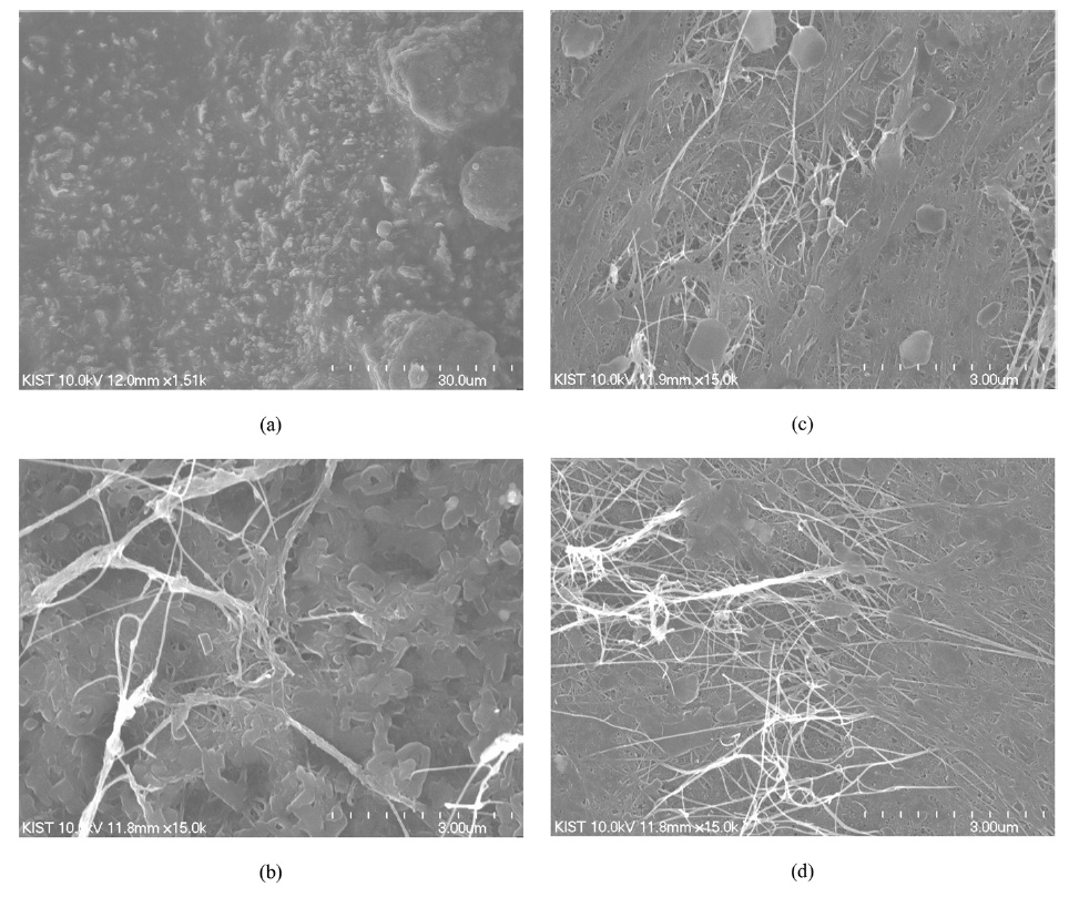
The surface of the CNT mat composites was observed by using SEM in order to shed light on the significant reduction of resistance and to investigate the surface morphology. Representative images are shown in Fig. 2. There was no CNT mat in the surface of the CNT mat composite prepared under a compression pressure of 0.5 MPa whereas CNTs were observed in the surface of CNT mat composites prepared under compression pressures of 9, 18, and 27 MPa. The CNTs were not fully connected in the case of the CNT mat composite prepared under a compression pressure of 9 MPa but they were fully connected in the cases of the CNT mat composites prepared under compression pressures of 18 and 27 MPa. Considering the resistance values of the CNT mat composites listed in Table 1, direct contact between four probes and the surface of the CNT mat composites with fully contacted CNTs gave resistance of 2.1 Ω. Therefore, the significant reduction of resistance of the CNT mat composites prepared under compression pressures of 0.5, 9, and 18 MPa is attributed to the development of the surface of the CNT mat composites with fully contacted CNTs.
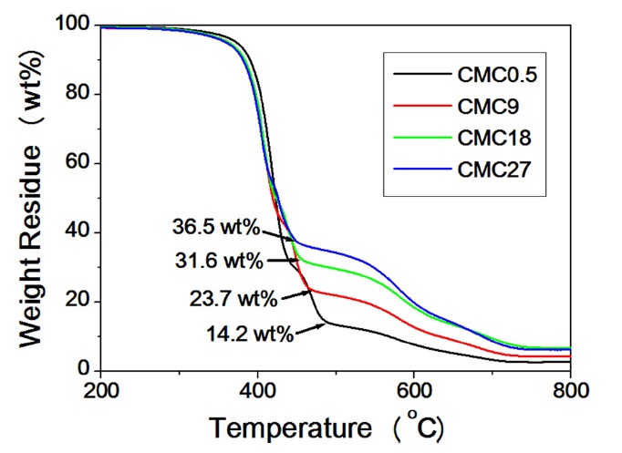
The weight fraction of the CNT mat in the CNT mat composites was analyzed by TGA, because this parameter was affected sensitively by compression pressure and it can influence the electrical conductivity of the CNT mat composite. The weight residue of the CNT mat composites is shown in Fig. 3 with respect to temperature. The determined weight fraction of CNT mat in the CNT mat composites increased with increasing compression pressure, as expected. Therefore, the difference between the electrical conductivity of the CNT mat composites prepared under compression pressures of 18 and 27 MPa is attributed to the reduction of the thickness of the composites with decreasing pCBT content in the composites with increasing compression pressure.
A fabrication method to improve the processability of thermoplastic CNT mat composites was investigated by using