As more satellites are designed to downlink their observed image data through the X-band frequency band, it is inevitable that the occupied bandwidth of a target satellite will overlap with that of other X-band downlink satellites. For sun-syn-chronized low earth orbit satellites, in particular, it can be expected that two or more satellites be placed within the look-ing angle of a ground station antenna at the same time. Due to the overlapping in the frequency band, signals transmitted from the adjacent satellites act as interferers, leading to degraded link performance between target satellite and ground station. In this paper, link analysis was initiated by modeling the radiation pattern of ground station antenna through a validated Jet Propulsion Laboratory peak envelope model. From the relative antenna gain depending on the offset angle from center axis of maximum antenna directivity, the ratio of received interference signal level to the target signal level was calculated. As a result, it was found that the degradation increased when the offset angle was within the first null point of radiation pattern. For a 7.3 m antenna, serious link degradation began at an offset angle of 0.4 degrees. From this analysis, the link performance of the coming satellite passes can be recognized, which is helpful to establish an operat-ing procedure that will prevent the ground station from receiving corrupted image data in the event of a degraded link.
Earth observation satellites such as TERRA and AQUA satellites are supposed to transmit their observed infor-mation or imaging data through the X-Band frequency band (8,025~ 8,400 MHz), which has already been allo-cated by the International Telecommunication Union Radiocommunication sector (ITU-R). On the other hand, the need to transmit high-resolution image data has re-cently emerged. For this reason, band-efficiency schemes such as dual polarization transmission have been applied (Maral et al. 1993). However, the allocated frequency band has been fully occupied due to the use of earth observa-tion satellites with high-resolution sensors. For example, in the case of the Korea Multi-Purpose SATellite-2 (KOMP-SAT-2), the center frequency and bandwidth of X-band downlink signal are 8,205 MHz and 320 MHz, respec-tively. Meanwhile, the center frequency and bandwidth of the AQUA satellite are 8,160 MHz and 15 MHz. Therefore, X-band downlink signal of AQUA is fully located at the in-band of KOMPSAT-2. Since the local time ascending node (LTAN) of each is different, there is no possibility of seeing dual-contact in KARI site, Daejeon. However, in the case of KOMPSAT-3, the considered LTAN is around 13 hours 30 minutes, which causes dual-contact with the AQUA satellite in a single ground station. Furthermore, the AQUA satellite is designed to keep broadcasting its X-band observation data to any ground station in the alongtracking path. For this reason, AQUA satellite can easily be expected to act as an interferer to the ground station that is supposed to be receiving KOMPSAT-3 image data.
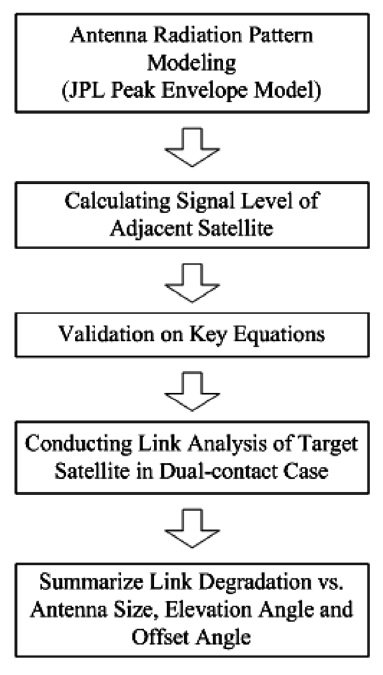
Fig. 1 shows the analysis procedure applied in this pa-per. For the calculation of the interference signal level, relative antenna gain vs. offset angle needs to be recog-nized in advance. Here, offset angle is the angle difference between target satellite and interference satellite. Since it is baseline that ground station antenna is tracking to the target satellite with its maximum gain, the interference signal level received at the ground station antenna is de-termined depending on the relative antenna gain of the ground station antenna. The relative antenna gain can be obtained from the modeling of an antenna radiation pat-tern using the Jet Propulsion Laboratory (JPL) peak en-velope model, which has already been validated in large-scale antenna applications of which the diameter versus wavelength is over 100 (Jamnejad & Peng 2006).
From the radiation pattern of the ground station mod-eled by the JPL peak envelope model, the signal level of the adjacent satellite received at the ground station is calculated using the relative antenna gain at any offset angle. Once the signal level of the adjacent satellite is ob-tained, it needs to be reflected into link analysis through key link equations. These key equations were validated by simulating a dual-contact scenario. After conducting validation on the key link equations, link analyses were conducted in the dual-contact case. Here, AQUA satellite was assumed to be the adjacent satellite. Through link analysis, the degradation caused by adjacent satellites was calculated according to antenna size, elevation angle and offset angle.
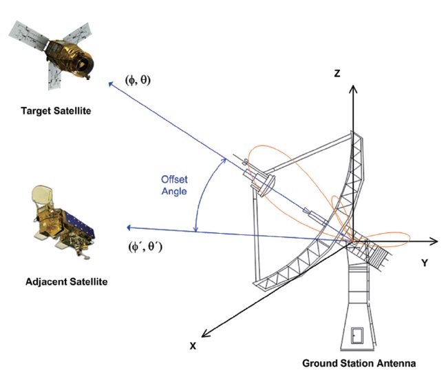
Fig. 2 illustrates the offset angle between target satellite and interference satellite. The meaning of the offset angle is the angle difference between the target satellite and the adjacent satellite. Normally, ground station antenna is supposed to perform tracking on the target satellite with its maximum antenna gain. Therefore, for the adja-cent satellite, signal level at the antenna output of ground station is determined through the relative antenna gain corresponding to the offset angle of the ground station antenna.
To calculate the offset angle, it is necessary to recog-nize azimuth and elevation angle of the ground station antenna in the direction of the target satellite and the ad-jacent satellite, respectively. The angle information can be obtained from orbit analysis based on the geo-location of ground station and two-line element file of each satel-lite. As a result of orbit analysis, antenna looking angle for target satellite and adjacent satellite can be expressed as azimuth angle (φ,φ') and elevation angle (θ,θ’) in spherical coordination. After transforming the angle elements as in rectangular coordination, Offset angle can be calculated in the form:
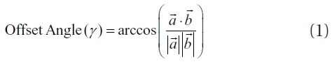
here,

is a vector when a ground station antenna is look-ing for the target satellite, and

is for the adjacent satel-lite.
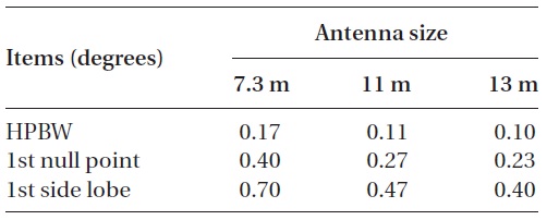
Table 1 shows the offset angle corresponding to half power beam width (HPBW), 1st null point and 1st side lobe at 8,205 MHz, which are obtained from the modeled 13 m, 11 m and 7.3 m antennas. Three different anten-nas have been used for KOMPSAT-2 satellite operation at Daejeon and Seoul. Indeed, those parabolic antennas will be applied for receiving X-Band image data from KOMP-SAT-3 satellite operation.
Compared with the measured HPBW, 1st null point, 1st side lobe of 7.3 m antenna manufactured by ViaSat, it was found that the JPL peak envelope model was accurate, with 0.125 degrees of difference. The radiation pattern of 13 m antenna was so sharp that the 1st null point was 0.23 degrees, while that of the 7.3 m antenna was 0.4 degrees.
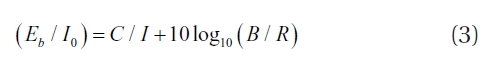
The overall Eb/No (ratio of bit energy to noise pow-er density) in a dual-polarized communication link, (
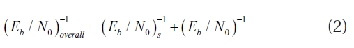
Here, (

Offset angle for angle for HPBW 1st null point and 1st side lobe of 13 m 11 m and 7.3 m antennas at 8205 MHz.
[Table 2.] Initial setup for validation test.
Initial setup for validation test.
Here,
Here,
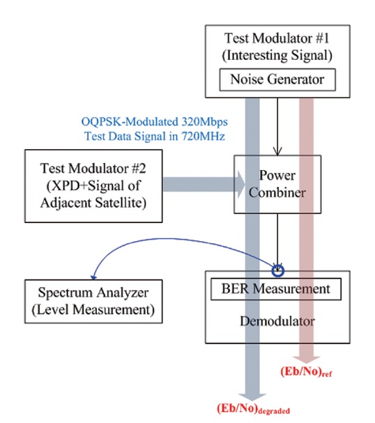
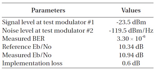
Fig. 3 shows the test configuration for the validation of the key equations. The aim of conducting this valida-tion test is to see if degradation on Eb/No is similar to the expected value based on key equations. Firstly, reference Eb/No, (Eb/No)
Test modulation #1 and #2 are working to generate test signals modulated through OQPSK with a data rate of 320 Mbps, which will be applied for one of two X-band down-link channels of the KOMPSAT-3 satellite. Test modulator #2 was working to generate a test signal corresponding to the XPD and signal of the adjacent satellite. Two signals generated by test modulator #1 and test modulator #2 were supposed to be combined at power combiner. Due
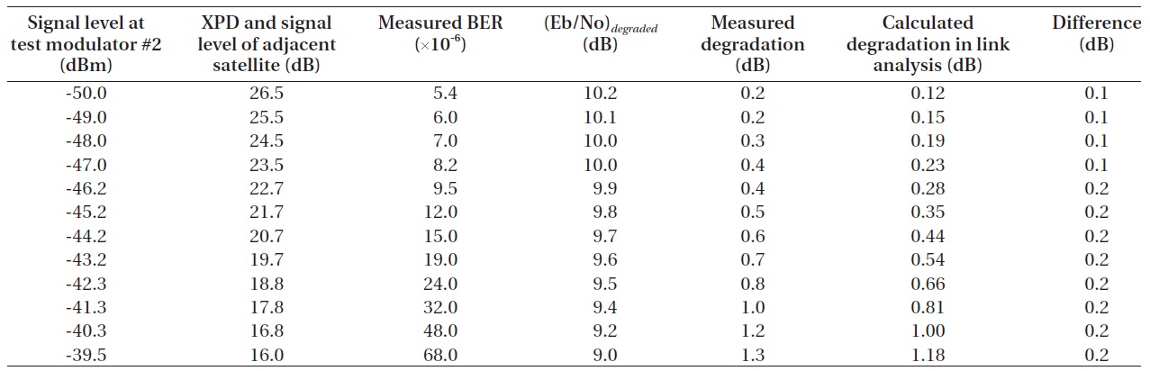
[Table 3.] Result of validation test.

Result of validation test.
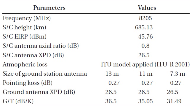
[Table 4.] Key link parameters between target satellite and ground sta-tion antenna.

Key link parameters between target satellite and ground sta-tion antenna.
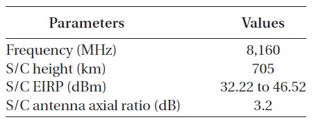
[Table 5.] Major link parameters of AQUA satellite.

Major link parameters of AQUA satellite.
to the combined signal, link degradation was reflected on the measured Eb/No, (Eb/No)
As an example for the link analysis, Table 4 shows link parameters between the target satellite and ground sta-tion antenna.
Table 5 shows the relevant link parameters of AQUA satellite in A-Train group, which was assumed as an adja-cent satellite in this paper. A-Train is the afternoon con-stellation consisting of several earth observation satellites belonging to National Aeronautics and Space Admin-istration and Centre National d'Etudes Spatiales (God-dard Space Flight Center 2003). Regarding the spacecraft equivalent isotropically radiated power, on-board an-tenna gain of AQUA satellite was designed to differ de-pending on the angle from antenna center axis (Goddard Space Flight Center 2002). The highest antenna gain is placed at an off-nadir angle of about 64 degrees, while the lowest one is placed at an off-nadir angle of 17 degrees.
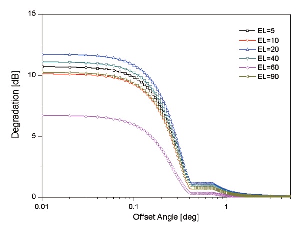
Fig. 4 shows, through the link analysis, that degrada-tion was dependent on the angle from peak of main beam in 7.3 m antenna. Link degradation significantly increases from an offset angle of 0.4 degrees, which corresponds to the 1st null of a 7.3 m antenna radiation pattern. Since the relative antenna gain was increasing from the 1st null point to the offset angle of zero degrees, the received in-terference signal was also increasing. On the other hand, it was shown that degradation in an elevation angle of 60 degrees was lower than even the case of 90 degrees eleva-tion angle. This was due to a characteristic of the AQUA on-board antenna in which the lowest relative antenna gain was located at 17 degrees from on-board antenna center axis.
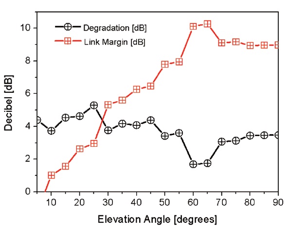
Fig. 5 shows the link margin and degradation versus
elevation angle, assuming that the offset angle was 0.3 degrees. According to the characteristics of the on-board antenna of the AQUA satellite, the degradation caused by the AQUA satellite was the lowest near an elevation angle of 60 degrees. On the other hand, link margin was contin-uously increasing, which was dependent on the elevation angle. The reason for increasing link margin was that dis-tance loss between satellite and ground station was lower when elevation angle was 90 degrees.
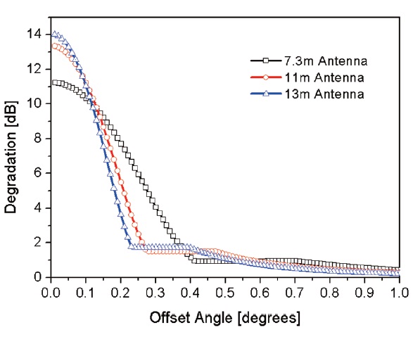
Fig. 6 shows the degradation depending on the anten-na size, assuming that elevation angle was 40 degrees and AQUA satellite was working as an adjacent satellite. It was shown that the offset angle where the degradation was dramatically increasing differed depending on the size of the antenna. According to the 1st null point of each an-tenna, the relevant offset angle was around 0.4 degrees in a 7.3 m antenna, 0.27 degrees in an 11 m antenna, and 0.23 degrees in a 13 m antenna.
In this paper, link degradation of target satellite was analyzed assuming that an adjacent satellite was also placed in the looking angle of the ground station an-tenna. Since the X-band for earth observation has been nearly occupied these days, degradation is expected due to the frequency overlap in the in-band of target satel-lite. For the analysis of the degradation, JPL peak enve-lope model was applied to model the radiation pattern of the ground station antenna. From the antenna radiation pattern, relative antenna gain was calculated depend-ing on the offset angle. Link equations were validated through bit error rate measurement. As a result of link analysis, assuming that AQUA satellite was an adjacent satellite, it was shown that link degradation was signifi-cantly increased from the offset angle related with the 1st null point of ground station antenna. In terms of satellite operation, an analysis of the degradation should be con-ducted when an adjacent satellite is expected to be in the antenna looking angle. If huge degradation is recognized, then mission planning should be modified to allow the regional-diversity and timing-diversity ground station to receive image data.