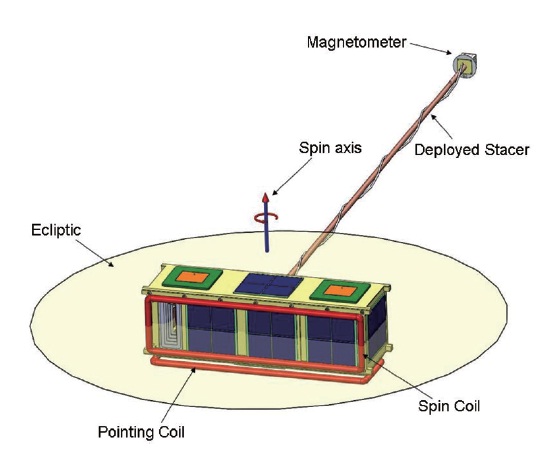
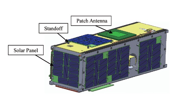
Triplet Ionospheric Observatory (TRIO)?CubeSat for Ion, Neutral, Electron, MAgnetic fields (CINEMA) is a space science mission with three identical CubeSats. Three institutes are collaborating to develop three CIN-EMA CubeSats: i) two CubeSats by Kyung Hee University(KHU) under its World Class University (WCU) program, ii) one CubeSat by UC Berkeley under the National Sci-ence Foundation (NSF) support, and iii) three magne-tometers by Imperial College, respectively. CINEMA is a 3-unit CubeSat, with an approximate size of 10 cm × 10 cm × 30 cm and mass less than 3 kg. Attitude control sys-tem uses two torque coils, one sun sensor and one mag-netometer and spins CINEMA spacecraft at 4 rpm with the spin axis perpendicular to the ecliptic plane as shown in Fig. 1. Three identical CubeSats will be built to carry out following scientific objectives: i) stereo imaging of mag-netospheric energetic neutral atom, ii) multi-point mea-
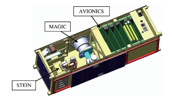
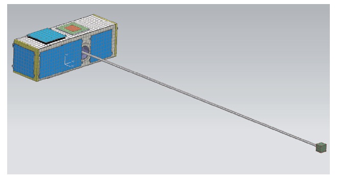
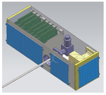
surements of suprathermal electrons and ions associated with auroral acceleration as well as electron microbursts, and iii) complementary measurements of magnetic fields for particle data. Each satellite is equipped with a Su-praThermal Electron, Ion, Neutral (STEIN) instrument covering the energy range ~2-200 keV, and a 3-axis mag-netometer of magnetoresistive sensors. CINEMA will be launched in July of 2012 and mission duration is one year. Operational orbit is 800 km sun-synchronous. Main com-ponents of external CINEMA consist of a magnetometer, solar panels, standoff, and patch antennas as seen in Fig. 2. In our case external surface of the satellite is covered with a lot of solar panels which are exposed to the sun ex-cept top & bottom side panels. The thermal conditions of external CINEMA was that the magnetometer is isolated from the body and top & bottom solar panels cannot re-ceive light from the sun in the orbit. Main components of internal CINEMA consist of avionics, the MAGnetometer Imperial College (MAGIC), and the STEIN as seen in Fig. 3. The thermal conditions of internal CINEMA is how to maintain operating temperature range of each compo-nent.
2.1 Requirements and Conditions for Thermal Analysis
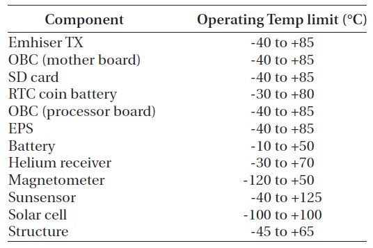
The objective of thermal analysis is to maintain all sub-systems and components of a spacecraft within their op-erating temperature limits for all mission phases (Gilm-ore 2002, Wertz & Larson 2008). Space environment can make all subsystems get variant temperature. So we have to maintain all subsystems and components within their operating temperature limits. There is some difference between operating temperature limit and non-operating temperature limit. Table 1 shows operating temperature limits of CINEMA component. Thermal control design and analysis were based on this operating temperature limit of each component. When the temperature of the battery is decreased less than -10°C, lifetime of the bat-tery will be shortened rapidly. On the contrary to this, when the temperature of detector is increased, thermal noise will be occurred on the detector. So it is very impor-tant to maintain the operating temperature limits of indi-vidual components in the orbit. Table 2 is orbit condition used in thermal analysis for CINEMA. For this thermal analysis, we assumed that the solar flux is 1,378 W/m2 at the spring or autumn equinoxes and used the fixed value of infrared radiation (IR) flux and albedo.
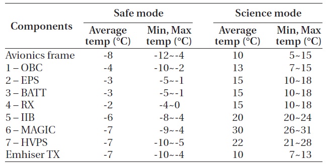
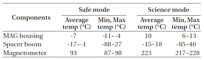
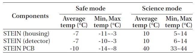
[Table 1.] Operating temperature ranges of CINEMA components.

Operating temperature ranges of CINEMA components.
[Table 2.] Orbit condition of CINEMA.
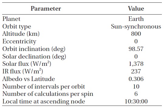
Orbit condition of CINEMA.
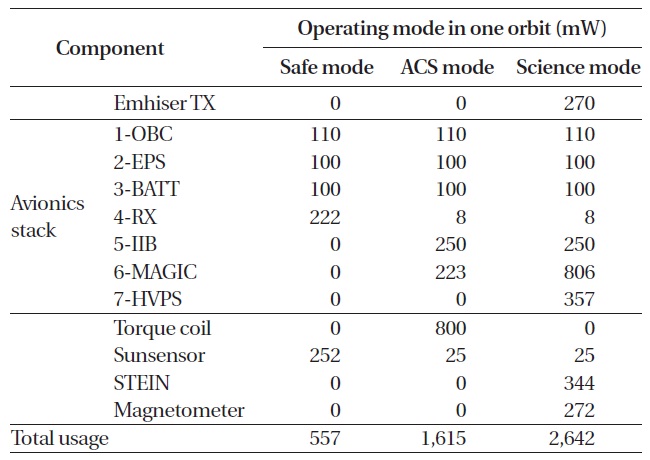
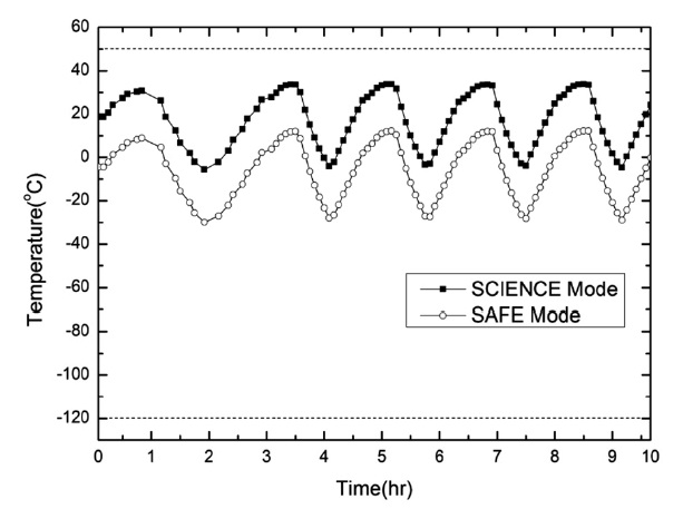
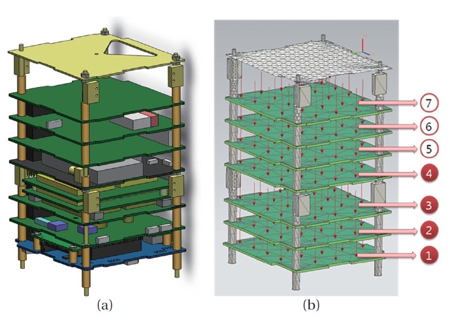
The heat dissipation of CINEMA has different value in each operating mode as shown in Table 3. Therefore, it is necessary to analysis when the heat dissipation of CIN-EMA is the highest value and the lowest value. We have analyzed two different cases at the Science mode and Safe mode. Fig. 4a shows the CAD model of avionics stack and Fig. 4b shows the thermal analysis model of avionics stack. Average heat dissipation was used for board level thermal analysis of avionics stack. At the safe mode, the heat dissipation of avionics is occurred only from stack number 1 through stack number 4.
2.2 Process for Thermal Analysis Using NX6.0 TMG
Computer application program, NX6.0 TMG (Siemens, Munich, Germany) is used to construct the thermal
[Table 3.] Average heat dissipation of avionics stack in one orbit.

Average heat dissipation of avionics stack in one orbit.
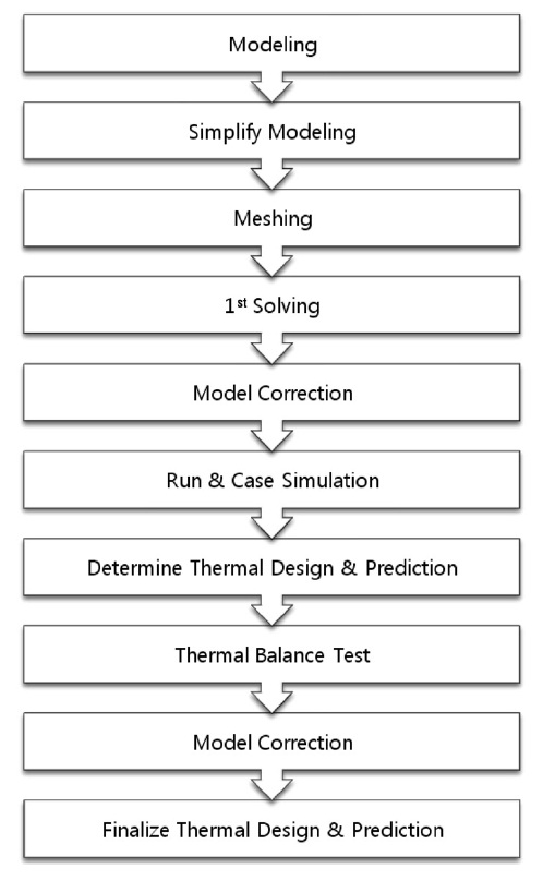
analysis model for CINEMA. The NX6.0 TMG program is based on the finite elements method (FEM) and it has capabilities of radiation exchange, conduction exchange and environmental heating by direct sunlight, albedo and IR emitted by the Earth. Fig. 5 shows steps of ther-mal analysis process for CINEMA. Because solving time of thermal analysis simulation is reduced more by us-ing a rectangular shape of mesh than using a triangular shape of mesh, we made a mesh with rectangular shape for all of external components of CINEMA, as shown in Fig. 6. The design of internal components of CINEMA is more complicate than external components. So we made
a mesh with rectangular shape and triangular shape for internal components of CINEMA, as shown in Fig. 7. Ta-ble 4 is material properties used in thermal analysis for CINMEA that are referenced from www.matweb.com web site. Many components of CINEMA consist of aluminum 6061 or 5052.
In order to get the better conduction between solar panel and chassis, we choose aluminum 6061-T6 for the material of standoff. Table 5 is thermo-optical properties used in thermal analysis for CINEMA that are offered by University of California Berkeley. In the table,
[Table 4.] Material properties of CINEMA.
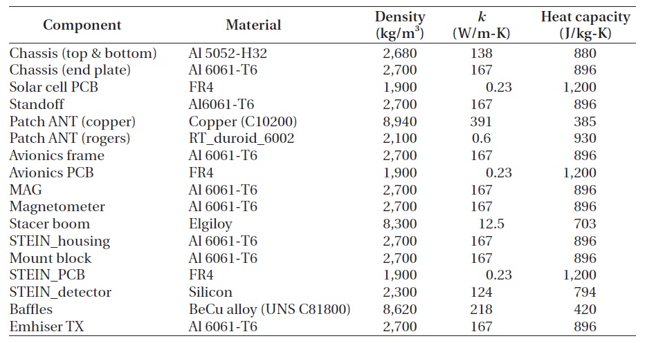
Material properties of CINEMA.
FEM is used for thermal analysis. To develop a thermal network and apply numerical techniques to its solution, we subdivide the thermal system into finite subvolumes called nodes. The thermal properties of each node are considered to be concentrated at the central nodal point of each subvolume. Each node represents two thermal-network elements, a temperature (potential) and a ther-mal mass (capacitance). Conduction conductors for rect-angular nodes are computed from the following (Gilmore 2002)
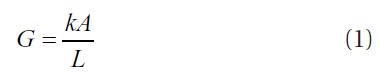
where
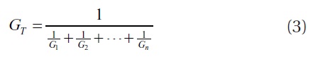
Two or more parallel conduction paths between nodes can be summed to create one conductor value by the fol-lowing equation (Gilmore 2002)
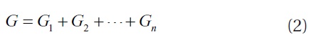
This equation can be helpful in computing an equivalent conductor between two nodes. This equation is used only in case of same materials and same shaped. Two or more series conduction paths between nodes can be combined
[Table 5.] Thermo-optical properties of CINEMA.
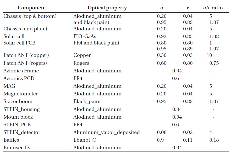
Thermo-optical properties of CINEMA.
to create one conductor value by the following equations (Gilmore 2002)
This equation is helpful in computing the conductors be-tween two dissimilarly shaped nodes or two nodes of dis-similar materials.
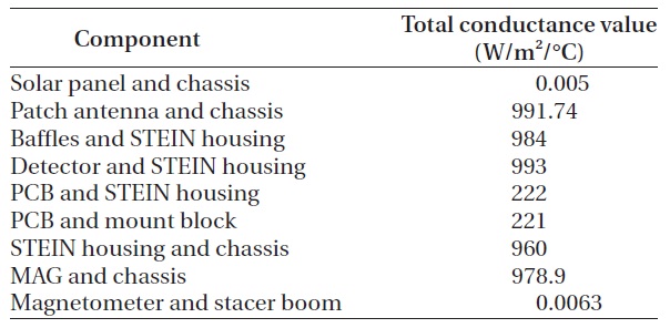
In order to solve conduction among components of CINEMA, it is necessary to calculate the total conduc-tance value. From the Eqs. (1-3), we can obtain the total conductance value between end plate and side plate. It can be calculated as Eqs. (4-6), where
[Table 6.] Total conductance value of all CINEMA components.

Total conductance value of all CINEMA components.
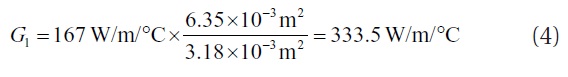
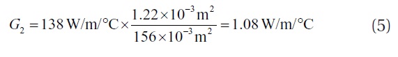
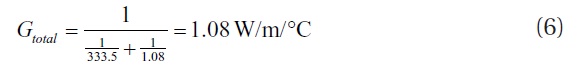
In the same way, the total conductance value of all CIN-EMA components can be calculated as seen in Table 6.
2.3 Results of Thermal Analysis
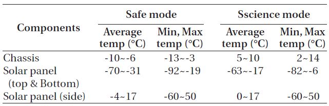
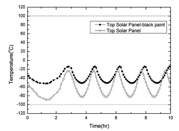
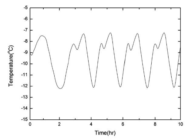
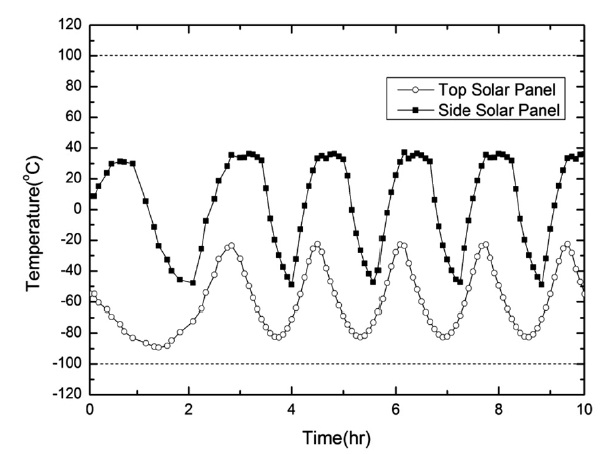
We could get results of thermal analysis using NX6.0 TMG program at the two different cases, safe mode and science mode. The one orbit period of CINEMA is 5,798 seconds and the end time of simulation is 30,000 seconds. All the data in this simulation was recorded every 300 sec-onds. Fig. 8 shows the analysis temperature of the chas-sis in the safe mode. The chassis is made of aluminum 5052-H32 and 6061-T6. The thermo-optical property of the chassis is alodined aluminum which has very high ra-tio of absorptance to emittance. Fig. 9 shows the analysis temperature of solar panels in the safe mode and science mode. The black square line indicates a temperature of the side solar panel and the white circle line indicates a tem-perature of the top solar panel. In this figure, we can see that the temperature of the top solar panel is much lower than the side solar panel. It is very dangerous because the operating temperature limit of the solar panel is -100°C to 100°C. So we need to devise new thermal control ap-proach to increase the temperature of the top and bottom solar panel so that the temperature is within their operat-ing temperature limit. Fig. 10 shows the analysis tempera-
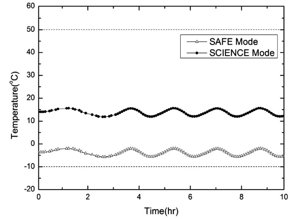
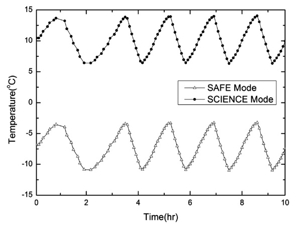
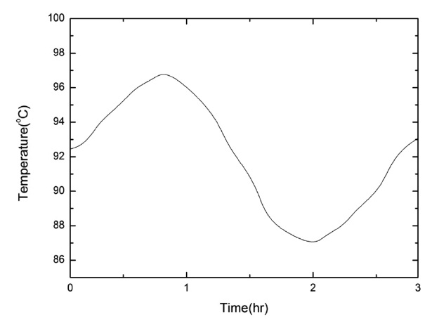
ture of BATT-printed circuit board (PCB) in the safe mode and science mode. We assumed that the temperature of BATT-PCB has equivalent value with real temperature of battery. So it is not necessary to make the thermal model of battery. The black circle line indicates a temperature in the science mode and the white triangular line indicates a temperature in the safe mode. We can know that the tem-perature of the battery in safe mode and science mode keep remaining within their operating temperature limit. Fig. 11 shows the analysis temperature of STEIN detec-tor in the safe mode and science mode. The black circle line indicates a temperature in the science mode and the white triangular line indicates a temperature in the safe mode. Because the material property of STEIN detector is silicon which has very high conductivity, the tempera-ture of STEIN detector is depending on a temperature of the STEIN housing which is made of aluminum 6061-T6. Fig. 12 shows the analysis temperature of the magnetom-eter in the safe mode. We can see that the temperature of magnetometer increased near 100°C. There is no thermal
interaction between the body of CINEMA and the mag-netometer and the thermo-optical property of the mag-netometer is alodined aluminum which has very high ratio of absorptance to emittance. That was because the temperature of magnetometer increased near 100°C. So we need to devise new thermal control approach to de-crease the temperature of the magnetometer so that the temperature is within their operating temperature limit (-120~50°C). Table. 7-10 summarize the analysis results of each component.
[Table 7.] Temperature of external components.

Temperature of external components.
[Table 8.] Temperature of AVIONICS.

Temperature of AVIONICS.
[Table 9.] Temperature of MAGIC.

Temperature of MAGIC.
[Table 10.] Temperature of STEIN.

Temperature of STEIN.
3.1 Passive Thermal Control Design
From previous results of thermal analysis, thermal control approaches are necessary to the top & bottom so-lar panel and magnetometer. Thermal control design has two different methods, the one is active thermal control method such as heater or cooler and the other is passive thermal control method such as coatings or surface fin-ishes (Gilmore 2002). In our case, active thermal control method cannot apply to CINEMA because of its small surface and low power. So we selected passive thermal control method for our CINEMA.
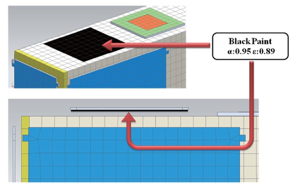
In the case of the top & bottom solar panel, the temper-ature of the top & bottom solar panel is very low and near -100°C. We thought that we could increase the average temperature of the top and bottom solar panels by using black paint on the surface of chassis and the inside of the top & bottom solar panels as shown in Fig. 13. The black paint which has a good emittance can emit a radiation from the chassis to the top & bottom solar panels satisfac-torily and the black paint which has a good absorptance can absorb a radiation from the chassis to the top & bottom solar panels satisfactorily. Radiation is only source to increase the temperature of the top & bot-tom solar panel because the top & bottom solar panel is isolated from the body of CINEMA and the surface area of standoff is very small.
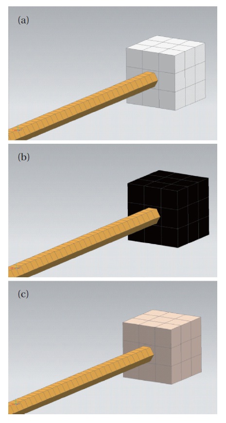
In the case of the magnetometer, the temperature of the magnetometer is very high because the thermo-op-tical property of the magnetometer is alodine aluminum which has very high ratio of absorptance to emittance. The temperature of the magnetometer is depends on
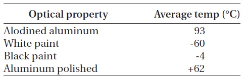
the ratio of absorptance to emittance. When we use the material which has a very high ratio of absorptance to emittance, the temperature will be increased and when we use the material which has a very low ratio of absorp-tance to emittance, the temperature will be decreased. From this idea, we tried to find optimized surface prop-erty of the magnetometer by simulations in each different case, white paint, black paint and aluminum polished as shown in Figs. 14a-c.
3.2 Results of Thermal Control Design
Figs. 15 and 16 are results of thermal analysis after us-ing passive thermal control design to CINEMA. Fig. 15 shows the temperature of the top solar panel using black paint to the surface of the inside of solar panel in the safe mode. The black square line indicates a new temperature of the top solar panel using black paint and the white circle line indicates original temperature of the top solar panel. By using black paint, we have increased the aver-age temperature of the top & bottom solar panels by 30°C.
Table 11 shows the analysis results of the magnetome-
ter for different cases. From this result, we chose the black paint as the surface of the magnetometer because the av-erage temperature of the magnetometer using black paint is the most optimal temperature for the magnetometer among others. Fig. 16 shows the temperature of the mag-netometer using black paint to the surface in the safe and
[Table 11.] Result of magnetometer.
Result of magnetometer.
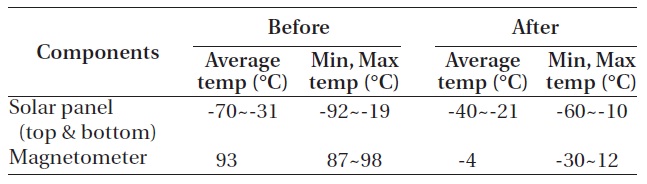
[Table 12.] Result of passive thermal control design in safe mode.

Result of passive thermal control design in safe mode.
science mode. We can know that the temperature of the magnetometer using black paint is kept within their op-erating temperature limit. By using black paint, we have decreased the average temperature of the magnetometer by -90°C. Table 12 summarizes the analysis results of pas-sive thermal control design.
As the CINEMA is a spin-stabilized satellite, it tends to be more stable for thermal environment in the space than 3-axis stabilized satellite. In addition, satellite is less af-fected by thermal variation which is caused by sunlight, albedo and Earth IR because of their small surface and small size. From the thermal analysis result of this paper, we could know that the main components of CINMEA are within the operating temperature limits except the top & bottom solar panel and the magnetometer. The black paint, which is the passive thermal control method, is able to increase 30°C of the average temperature of the top & bottom solar panel. Besides, it is able to decrease -90°C the average temperature of the magnetometer. At last, Solar panels and the magnetometer can maintain within their operating temperature limits by using black paint and all of the thermal requirements of CINEMA are met successfully by means of the passive thermal control design. The active thermal control design is not available in case of the nano-satellite because of power consump-tion and space limitation. Therefore the passive thermal control is better way to overcome thermal problems in the CubeSat scale satellite. We expect that this study is one of the important roles to develop the CubeSat mission.