Triplet Ionospheric Observatory (TRIO) CubeSatforIon, Neutral, Electron MAgneticfields (CINEMA) is a CubeSat with the weight 3 kg that will be operated in the orbit conditions of about 800 km altitude and 90° inclination angle, using the S-band and ultra-high frequency (UHF)-band communication frequencies. Regarding the communication antenna loaded on the satellite, the two patch antennas has the downlink function in the S-band, whereas the two whip antennas has the function to receive the command sent by the ground station to the satellite in the UHF-band. The uplink ground station that communicates through the UHF-band with the CINEMA satellite was established at Kyung Hee University.The system is mainly composed of a terminal node controller, a transceiver, and a helical antenna. The gain of the helical antenna established at the Kyung Hee University ground station was 9.8 dBi. The output of the transceiver was set to be 5 W (6.9 dB) for the communication test. Through the far-field test of the established system, it was verified that the Roman characters, figures and symbols were converted into packets and transmitted to the satellite receiver in the communica-tion speed of 9,600 bps.
There are at present about 100 CubeSats that have been launched and used in various areas including earth observation, low earth orbit mobile communication and space science experiments (Bouwmeester & Guo 2010). CubeSats have the advantages that it takes a short pe-riod of time from the mission settings to the design and launch, and that the fabrication costs less. Taking such advantages of the Cubesats, universities in the U.S., Ja-pan and Switzerland fabricate CubeSats for the purpose of education by establishing a platform for technological test and scientific mission.
A CubeSat is a small satellite with the accurate volume of 1 Land the weight of 1.33 kg (Hunyadi et al. 2002). The unit size of a standard CubeSat is 10 × 10 × 10 cm, and the CubeSat of the size is called 1 U CubeSat.
Triplet Ionospheric Observatory (TRIO) CubeSat for Ion, Neutral, Electron, MAgneticfields (CINEMA) is the CubeSat developed by the Kyung Hee University with UC Berkeley and Imperial College London. CINEMA is a 3 kg, 3 W CubeSat on which Supra Thermal Electron, Ions, Neutrals (STEIN), the micro-sized high-tech particle de-tector that can detect proton, neutron and electron, as well as MAGnetometer Imperial College (MAGIC) for magnetic field measurement. Three TRIO-CINEMA satel-lites are fabricated, two by the Kyung Hee University and one by UC Berkeley.
A CubeSat communicates with the ground station us-ing the armature radio communication frequency in the very high frequency (VHF) and ultra-high frequency (UHF) bands. A CubeSat transmits a beacon signal to the ground station just after launching in order to inform the position of itself, and some Cubesats communicates with the ground station through the beacon signals carry-ing on the status information of themselves (Bryan et al. 2009). Packet data are transmitted when the command is transmitted from the ground station to the satellite, and the data follow the AX.25Protocol.
On the other hand, CINEMA employs the UHF-band which is for the armature radio communication frequen-cy for uplink, while it transmits the measurement data to the ground station through the S-band for downlink. It transmits a beacon signal to the ground station just af-ter launching in order to inform the position of itself, and then the ground station transmits the command to turn off the beacon signal after verifying the position of the satellite. After that, the satellite is operated by means of packet communication.
This article describes the establishment of the commu-nication system between the CubeSat CINEMA and the ground station for the uplink communication as well as the communication test of the system.
2. COMMUNICATION SYSTEM OF CINEMA
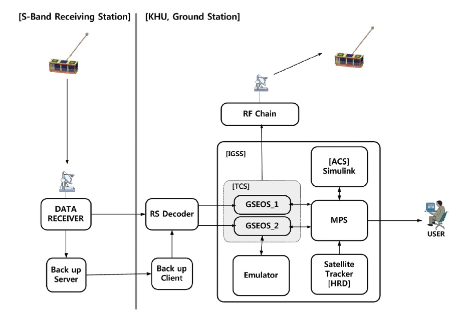
Fig.1 is the diagram that represents the ground systems that are to communicate with the CINEMA satellite. Since the CINEMA ground systems are geographically separat-ed, they need to be connected.
For the downlink, the satellite transmits data to the ground station in the 2,200 MHz band which is within the S-band. The status information of the satellite and
the scientific data measured by the payloads are encoded into Reed Solomon codes and transmitted through the FM method at the speed of 1 Mbps. The S-band ground station stores the data received from the satellite in a hard disk and then transmits it to the ground station at Kyung Hee University. The two ground stations are con-nected through the conventional internet network, and the all the data received from the satellite are processed in the ground station at Kyung Hee University. The trans-mitted satellite data are transferred to the Ground Sup-port Equipment Operating System (GSEOS) as digital signals in the Consultative Committee for Space Data Systems (CCSDS) frame type, and then displayed on the computer in the form of CCSDS packet through the GSEOS. The ground station at Kyung Hee University di-rectly controls the S-band destination station in order to make the ground operation smooth. Getting an idea from the example of University of Stellenbosch, South Africa, where the software was designed in order to integrate the ground stations through the internet network to enable multiple missions, the two ground stations of the CIN-EMA Mission were also connected through the internet (Barry & Nel 2002).
For the uplink, the Kyung Hee University ground sta-tion analyzes the data received from the satellite, gener-ates the commands required for the satellite operation and transmits them to the TNC as the CCSDS packets through GSEOS. The data type follows the AX.25 Proto-col (William et al. 1997). The data are modulated by the 9,600 bps Gaussian low-pass-filtered minimum shift key-ing (GMSK) for communication. The digital type data re-ceived from the computer is converted to the analog type by the terminal node controller (TNC) and transmitted to the transceiver. The transceiver then transmits the com-mands received from the TNC through the helical anten-nas. The data transmission and receipts are performed through the tape carrier package protocol except the ra-dio frequency (RF) instruments (Tarun et al. 2006).
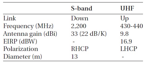
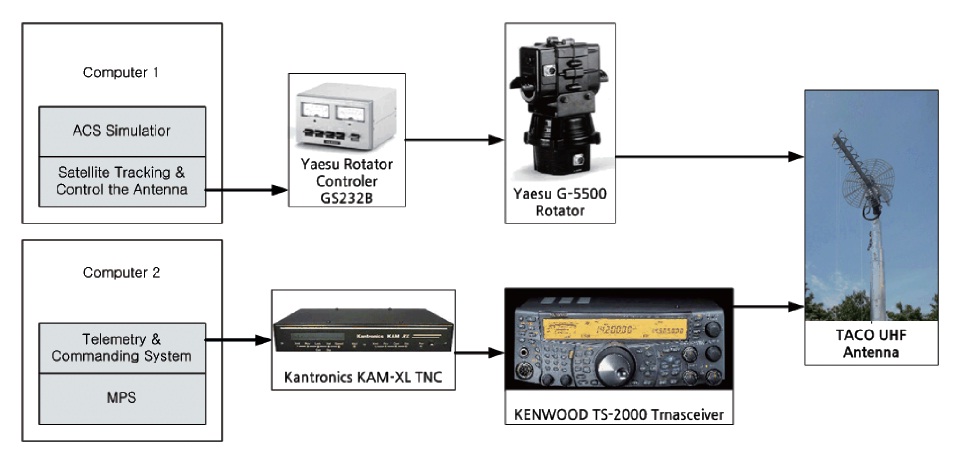
Fig. 2 shows the Kyung Hee University ground system established according to the communication specifica-tion (Table 1) and the instrument composition. All the instruments constituting the ground station established at Kyung Hee University are commercial products. CIN-EMA is operated with two computers. Computer 1 is used to execute the attitude control system simulator, operate the satellite tracking software, and control the antenna rotator controller so that the antennas can automati-cally track the satellite during the period when connec-tion with the satellite is possible. The real-time position of the satellite is shown on the monitor of Computer 1.
[Table 1.] CINEMA communication data.

CINEMA communication data.
Computer 2 analyzes the data received from the satellite through the mission planning system (MPS). On the basis of the analytical results, the MPS generates commands that are transmitted to the satellite through the GSEOS. The TNC and transceiver are respectively connected with Computer 2 through RS232 cables. The TNC converts the digital signals to analog signals and then transmits them to the transceiver through the prepared cable. Finally, the commands of the ground station are transmitted through the helical antennas (Kim 2003).
The TNC is the instruments that converts digital sig-nals to analog signals or inversely. The function is simi-lar to that of a wire modem, serving as a sort of interface that connects a transceiver and a computer. The KAM-XL model (Kantronics) is used as the TNC for the CINEMA operation which allows data modulation into the GMSK type and communication at the speed of 9,600 bps.
A transceiver is an instrument that is used in amateur radio communication to transmit and receive voice sig-nals with a far counterpart, being connection with an an-tenna. Using such a function, the signals converted by the TNC from digital type to analog type are transmitted to the transceiver and then the commands are consequently transmitted to the satellite through the antenna. The out-put of the transceiver on the ground is 20 W according to the requirement of the CINEMA. The TS-2000 model of Kenwood (Shibuya, Tokyo, Japan), which enables com-munication in the 430 MHz band, is used for this study.
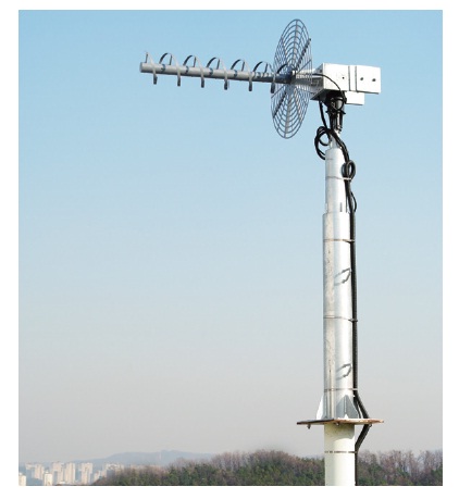
The Uplink antenna required for the CINEMA Mis-sion needs to enable communication in the range of 400 MHz~500 MHz and the antenna gain needs to be higher than 9 dBi. To meet the requirements, the H-065 model (TACO, Harrisburg, PA, USA) was established at the Kyung Hee University. Fig. 3 shows the antenna installed at the Kyung Hee University ground station.
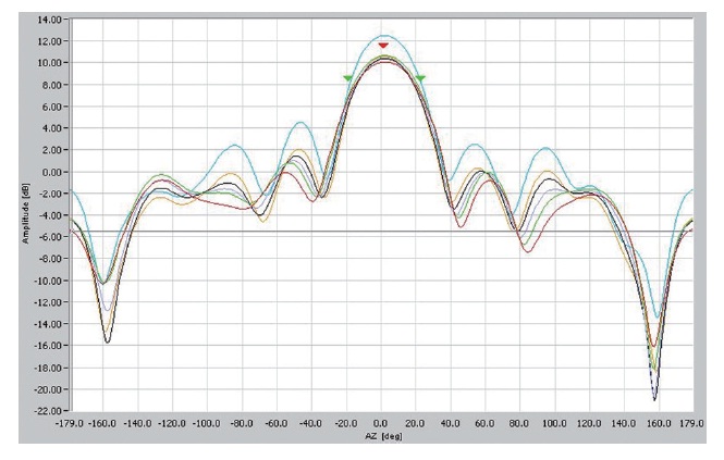
To verify the characteristics of the antenna, the an-tenna pattern and gain were measured by the Radio Re-search Laboratory. Fig. 4 shows the measured antenna pattern, indicating that the antenna gain is 9.8 dBi if it is used in the left hand circular polarization directivity and 435 MHz band (blue line).
The TNC is the instrument that is firstly passed through
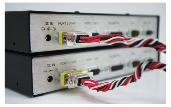
by the commands transmitted from the ground to the satellite. For this reason, a test was performed to verify whether the TNC transmits the data from the computer to the transceiver. For the test, two TNCs were individual-ly connected with the computers through the RS232 cable so that the data transmitted and received by the terminal software could be checked out. The two TNCs were con-nected through the nine-pin cable with the No. 2 Ports for the UHF-band at the rear side of the TNC instrument, as shown in Fig. 5. The result showed that the Roman char- acters, symbols and figures transmitted by the terminal software were received without an error by the TNC of the receiving part.
4.2 Transceiver Voice Transmission Test
To test the voice transmission through the transceiver, the two transceivers were connected through the nine-pin cable with the UHF-band connectors in a similar way used for the TNC test. The transceivers were set to the FM mode, and the frequency of both transceivers was set to be 435 MHz for the transmission and reception of voice signals. The result showed that there was no occasion where the voice was discontinued or not heard because of noise, although the voice signals were mixed with noise. The counterpart in the communication accurately re-ceived all the transmitted voice signal information.
4.3 Test of the Connection between the TNC and the Transceiver
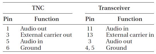
The port through which the TNC signals are put out is a nine-pin port, while the port through which signals from the TNC are put into the transceiver is a 13 Din pin. Since the type and pin number of the input and output port of the TNC and the transceiver are different, a cable was pre-
pared according to the pins through which signals of each port are input and output. Table 2 shows the number of pins of the ports to connect the TNC and the transceiver.
As in the case of the test with two TNCs, two transceiv-er-TNC connection sets were used for the test. Each TNC was connected with the computer. The result showed that the data were transmitted and received through the ter-minal software without an error.
CINEMA is to be operated at the altitude of 800 km. When a satellite is operated on a low earth orbit, Dop-pler’s effect is caused depending on the velocity of the satellite (Du 2005). To solve the problem, the ham radio deluxe (HRD) software, which is often used for amateur radio communication, is employed. HRD enables to con-trol the calculated position of the satellite through an an-tenna and track the satellite position automatically, and monitors the frequency deviation by Doppler’s effect. Additionally, it controls the functions of transceivers by
[Table 2.] TNC &transceiver radio connector interface.

TNC &transceiver radio connector interface.
means of a computer, performs tracking of the satellite orbit by calculating the two line elements (TLE) values called from the North American Aerospace Defense Com-mand (NORAD) and the display the real-time position of the satellite on the software monitor over the world map. The test was performed to verify if the HRD functions could be applied to the instruments of the Kyung Hee University ground station.
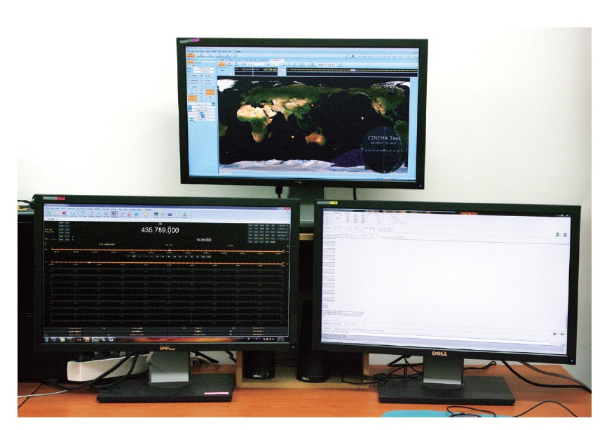
Two tests were performed simultaneously: 1) The HRD software was executed by Computer 2 of the ground sta-tion, an arbitrary satellite was selected, and the orbit of the satellite was tracked. 2) The frequency deviation change by Doppler’s effect was applied to the connected transceiver. In Fig. 6, the top monitor shows the current position of the satellite on the map based on the TLE val-ues calculated by the HRD. The monitor on the left shows the current status of the transceiver as the transceiver is connected with the computer. When the software performs tracking of the satellite position, the frequency de-viation by Doppler’s effect is calculated simultaneously. The result showed that the HRD displayed the continu-ously changing frequency value on the monitor and con-verted the frequency of the transceiver simultaneously.
4.5.1 The performance test of the ground station UHF-band helical antenna
To test the performance of the helical antenna, com-munication was attempted from the position about 1 km away from the ground station laboratory where the transceiver used for the CINEMA satellite operation was installed. The result showed both sides transmitted and received accurate voice signals, indicating that there was not a problem in the performance of the antenna.
4.5.2 Measurement of the performance of the UHF-band whip antenna for the satellite
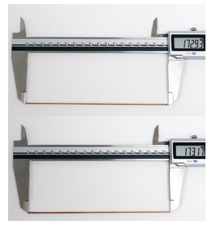
The UHF-band antennas used by CINEMA are made of beryllium copper. According to the design, the diameter of the beryllium copper antenna is 1 mm, the length is 173 mm, and it is fabricated by connecting it with a sub-miniature type A (SMA) male type connector. Two UHF-band whip antennas are installed at both sides of the CINEMA satellite main body. Fig. 7 shows the fabricated whip antennas.
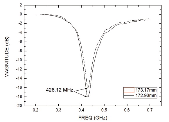
The performance of the fabricated antennas was mea-sured with a network analyzer (model: Anritsu 37269C). As shown in Fig. 8, the measured center frequency of both antennas was 428.12 MHz. The beam width of the 173.17 mm antenna was about 40 MHz between 410.625 MHz and 450.000 MHz, and that of the 172.93 mm antenna was about 53 MHz between 403.75 MHz and 456.25 MHz. Since the center frequency that is to be used by the CIN-EMA satellite is 435.789 MHz and 436.211 MHz, and the beam width required for the CINEMA satellite is 30 kHz, the fabricated antennas of which length followed the de-sign satisfied the functional requirements.
4.6 Test of the Wire Communication System
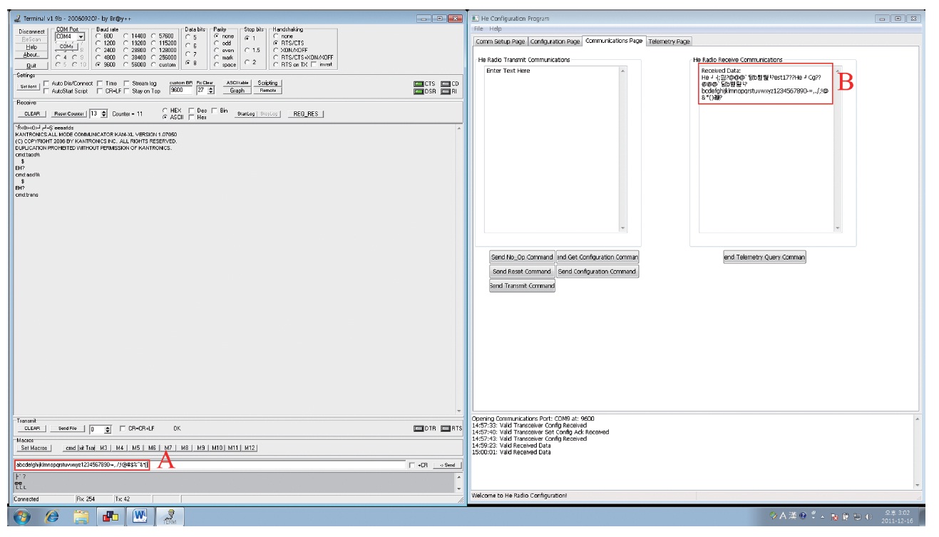
To test if the uplink RF chain system, excluding the he-lical antennas, has any problem in data transmission, a wire communication test was performed by connecting the transmitter of the ground station and the receiver of the satellite through the RF cable (Fig. 9). The system for the test consisted of computer (terminal) ?UHF receiver of the satellite?transmitter?TNC?computer (terminal). The transmitter of the ground station and the receiver of the satellite were connected with 1 m RF cable. The data in which Roman characters, symbols and figures were mixed together was transmitted through the termi-nal software through the TNC and the transceiver. It was verified that the transmitted data were received in packet type by the configuration software provided by the pro-ducer of the satellite receiver. Fig. 10 is the screen shot of the terminal software connected with the ground station transmitter and the data received by the configuration software of the receiver for the satellite. The left of Fig. 10 is the terminal software with the A part showing the trans-mitted data and the B part showing the data received by the receiver. The B part shows Chinese character types before and after the data, which are the packets produced by the TNC following the AX.25 Protocol.
4.7 Wireless Communication Test (Long-Distance Ground Test)
As verified in Section 4.6, after checking out that com-munication was performed using the RF cable, the satel-lite receiver was connected with the UHF-band antenna fabricated in Subsection 4.5.2 to test the uplink wireless communication. Since the communication was per-formed not a cable but an antenna, a Far-Field test was performed from a position that was far from the antenna. The range of Far-Field according to the antennas was cal-culated by the following equation (Radio Communica-tions Unit-ICTP, 2004):
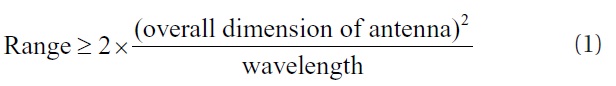
In Eq. (1), the overall dimension of antenna was substi-tuted by the length of the ground station helical antenna, 1.72 m, and the wavelength by the wavelength corre-sponding to the frequency of 435.789 MHz, which is 0.687 m. The calculation showed that the range of the far-field in the UHF-band from the helical antenna installed at the Kyung Hee University was more than 8 m.
Thus, the satellite receiver was installed on a building rooftop about 1 km away from the helical antenna. An at-tenuator was connected at the outlet of the transceiver to
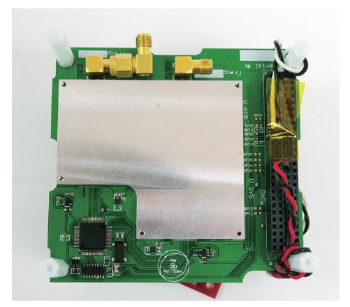
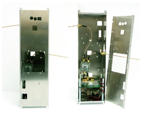
give loss of 100 dB, and the output of the transceiver was set to be 5 W. The data received by the satellite receiver and the whip antenna constituted in the structure mod-el shown in Fig. 11 were verified by the satellite receiver configuration software in the laptop computer connected with the satellite receiver.
The two CINEMA satellite produced by Kyung Hee University are planned to be launched in late 2012 by the Dnepr, the Russian projectile. Since the uplink and downlink ground stations for the communication with the CINEMA satellites are geographically separated, the two ground stations are connected through the internet. The uplink employs the frequencies of 435.789 MHz and 436.211 MHz that are used for amateur radio communi-cation, while the downlink employs the frequencies of 2,212.3 MHz and 2,221.1 MHz for communication.
The CINEMA communication system has been estab-lished by combining commercial products that satisfy the CINEMA requirements. Among them, the ground station established by Kyung Hee University is mainly composed of helical antennas, transceivers and TNCs. The helical antenna, which is one of the parts of the ground station, was measured to have the gain of 9.8 dBi at 435 MHz in the UHF-band. The transceiver utilizes 435 MHz at the output of 20 W. The commands to operate the satellite are generated by the GESOS software. The HRD software tracks the position of the satellite and controls the anten-na rotator by calculating the frequency deviation caused by Doppler’s effect.
Two whip antennas made of beryllium copper are in-stalled on the satellite. The commands transmitted from the ground station are received by the receiver available in the UHF-band.
At present, the uplink for the communication with the CINEMA satellite is established at the Kyung Hee Uni-versity Observatory. After connecting the individual in-struments, the ground station communication system was tested to see if they were connected with each other successfully. The test performed by the transmission and reception of the data composed of simple Roman charac-ters and figures indicated a successful connection. To per-form a Far-Field test, data were transmitted and received through the helical antenna installed at the observatory that is far by 1 km or more and the satellite UHF-band whip antenna. The data rate was 9,600 bps. The config-uration software of the receiver showed that the packet data were received by the receiver.
The CINEMA communication system developed in this study enables to carry out multiple missions through the simultaneous operation of the two satellites by automati-cally tracking the satellites according to the time when the satellite contacts with the ground station. Moreover, since the system was constituted with commercial products, it has a higher reliability and a lower probability of failure than that of newly developed equipment. Therefore, even in the future cases where additional communication may need to be performed in a bandwidth which is not the UHF-band or at a communication rate which is not 9,600 bps, a little modification of the ground system will allow the current system to be applied to a new mission. As a result, a new system may be rapidly constituted by mini-mizing the time required for equipment development.
Tests will be continuously performed in the future in order to establish a stable and highly reliable communi-cation system.