The Korea Astronomy and Space Science Institute and the Department of Astronomy at the University of Texas at Austin are developing a near infrared wide-band high resolution spectrograph, immersion grating infrared spectrometer (IGRINS). The compact white-pupil design of the instrument optics uses seven cryogenic mirrors, including three aspherical off-axis collimators and four flat fold mirrors. In this study, we introduce the optomechanical mount designs of three off-axis collimating mirrors and one flat slit-viewer fold mirror. Two of the off-axis collimators are serving as H and K-band pupil transfer mirrors, and are designed as system alignment compensators in combination with the H2RG focal plane array detectors in each channel. For this reason, the mount designs include tip-tilt and parallel translation adjustment mechanisms to properly perform the precision alignment function. This means that the off-axis mirrors’ optomechanical mount designs are among the most sensitive tasks in all IGRINS system hardware. The other flat fold mirror is designed within its very limitedly allowed work space. This slit-viewer fold mirror is mounted with its own version of the six-point kinematic optics mount. The design work consists of a computer-aided 3D modeling and finite element analysis (FEA) technique to optimize the structural stability and the thermal behavior of the mount models. From the structural and thermal FEA studies, we conclude that the four IGRINS mirror mounts are well designed to meet all optical stability tolerances and system thermal requirements.
Since the early nineteenth century, astronomical spectrographs have been used to analyze the light emitted by stars and various celestial bodies (Hearnshaw 2009). A spectrograph splits or disperses the light from an object into its wavelength components so that it can be recorded and interpreted. One of the most important components in astronomical spectrographs is the diffraction grating (Massey & Hanson 2011). Today, there is a newly developed technology called immersion grating, which is particularly useful for high-resolution infrared spectroscopy (Jaffe et al. 1998, Marsh et al. 2007). Using silicon micromachining techniques for fabrication, immersion grating shows great potential as an alternative dispersing element to the classical surface-relief gratings. Moreover, its high efficiency compared to other dispersive devices in terms of spectral-resolution to beam-size allows a spectrograph to be built with a physical volume dramatically smaller than that of a comparable instrument built around conventional gratings (Tokunaga et al. 2008, Yuk et al. 2010).
Immersion grating infrared spectrometer (IGRINS) is a high-resolution near-infrared spectrograph that is designed to be compatible with telescopes ranging in diameter from 2.7 m (the Harlan J. Smith telescope, HJST) to 8 m, and was created through collaboration between the Korea Astronomy and Space Science Institute and the Department of Astronomy at the University of Texas at Austin. As the aim of the IGRINS project was to maximize the scientific productivity of the instrument, it has been designed to work with the largest simultaneous wavelength coverage possible while maintaining a fairly high spectral resolution, λ/Δλ = 40,000.
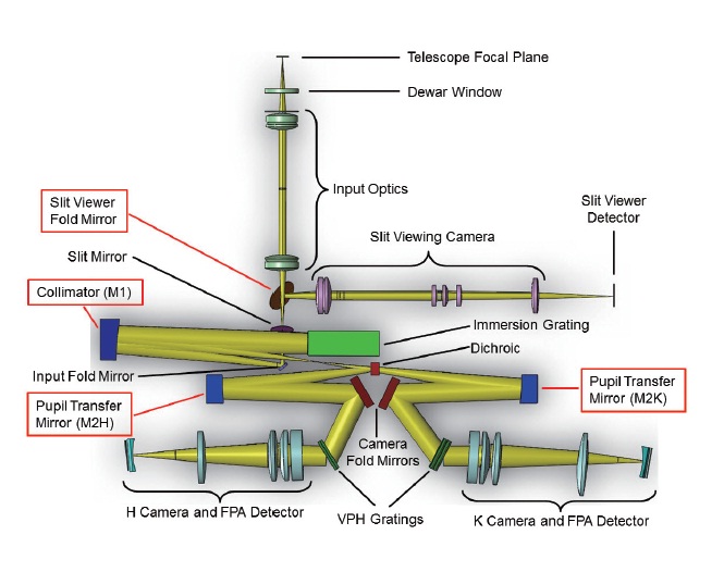
The spectrograph will be operated at a temperature of 130 K with detectors of 65 K, and all the internal components are designed under the cryogenic condition typical for a near-infrared instrument (Baumeister et al. 2003, Kanneganti et al. 2009). The different f-ratio for each candidate telescope means that an adjustable focal conversion pre-slit optics and a slit monitoring imager are required for rapid target acquisition. The IGRINS optical design shown in Fig. 1 consists of white pupil optical configuration (Schroeder 2000). The full optical train uses a total of seven cryogenic mirrors: three aspherical off-axis collimators and four flat fold mirrors. After the light beam passes through the slit and the input fold mirror, it runs to the primary collimator (M1) followed by the echelle dispersion, and the collimator secondarily reflects the beam to form a column of multicolored images of the dispersed slit. A dichroic is placed just after the polychromatic foci in order to split the beam into two spectrograph arms where H and K pupil transfers (M2) are located (Jaffe 2011).
The optical performance of a mirror can be significantly degraded by an inappropriate mounting configuration. A successful mounting job should minimize optical distortion and provide a simple means of alignment (Thornton 2002). Therefore, achieving good structural and thermal stability performance is critical for a compact high-magnification instrument such as IGRINS. Optical tolerance governs the manufacturing methods and assembly procedures. Fabrication cost, time, and difficulty all depend on required tolerance, as well as the reproducibility of performance. With the aid of the finite element analysis (FEA) method, we investigate the mirror surface degradation due to the gravitational flexure and the component supporting mechanism.
Several distinctive features make this study different from previous optomechanical design work in similar areas. One of the top selling points of using an immersion grating in a high resolution spectrograph is its compactness. The IGRINS optics design also makes full use of this advantage of the immersion grating, thus leaving the component-mounting optomechanics closely packed in a limited space. For this reason, we provide various technical approaches to resolve the overpopulated space issue throughout the article (primarily in Section 2). The other design challenge in this work comes from the high-precision alignment flexibility required as a role of the optics system compensators, especially for the pupil transfer mirrors in both H and K channels. To properly serve this alignment requirement, we have adopted the precision adjustment “bumper” idea and improved the performance to a certain extent (Section 2.2).
Another design point to be underlined in this study is from the slanted surface of the slit-viewer fold mirror. We have avoided the apparently complicated angular-tolerance-involved fabrication issue and reduced the chance of unnecessarily high cost and effort being required for manufacturing by separating the tilted part and the vertical-horizontal part. In addition, the optical stability tolerances of the whole IGRINS system are significantly tight to make it challenging to meet the required stabilities for the moving instrument at the back end of a candidate telescope. Although there is no technologically progressive point where we have adjusted all the mount parameters to be within the given tolerances, it must be a fundamental and critical goal of this design work to pursue the satisfaction of those system requirements.
In this paper, we describe the overall procedure of optomechanical mount designs of the three collimating mirrors and the slit-viewer fold mirror used in the near-infrared high-resolution spectrograph IGRINS. In Section 2, the design requirements and the mechanical modeling of the mirrors are presented. The results of structural analyses and thermal studies for the mount models are discussed in Sections 3 and 4, respectively. The last section summarizes the paper and draws some conclusions.
In an optomechanical mount design, one must first consider the level of requirement from the optical design for alignment and stability tolerances, which is derived from the sensitivity analysis of the optical system examining any probable perturbation. IGRINS optical tolerance analysis defines aspheric constants, decenters, tip-tilts, surface figures, and separations, which should not be set too loose or too tight but be balanced between performance and manufacturing cost. These tolerances apply to lens and mirror diameters, thickness, airspace, surface quality, precision of centering, etc. A decentered optics shows coma on the axis, whereas a tilted element leads to a tilted field. While some surfaces are affected very little by a small tilt, others may extremely be sensitive in this regard (Kingslake & Johnson 2010).
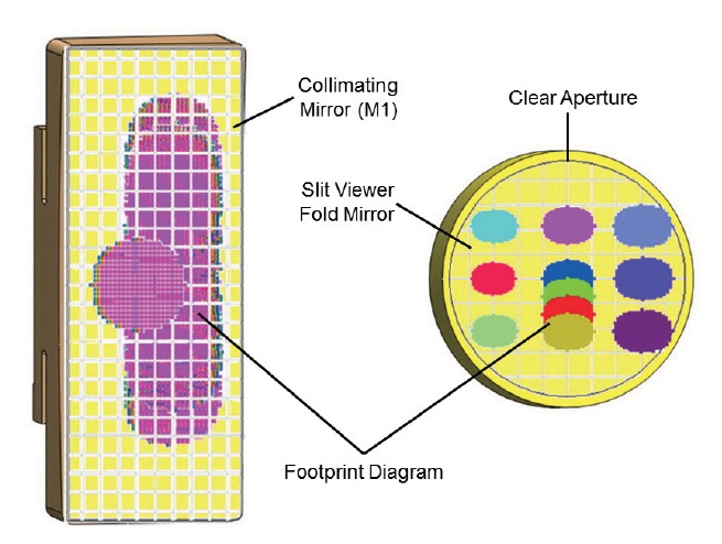
The dimensions of each mirror, both the powered and the flat, need to be optimized between the space availability and the clear aperture (CA) of an optical surface. The IGRINS optical design is quite compact throughout the optical deployment, and mirrors are located in the crowded area. The physical specifications of the four mirrors, to be treated in this design study, are shown in Table 1. Examples of mirror surface CA are displayed in Fig. 2 for the M1
collimator and the slit-viewer fold mirror. In the next three subsections, we describe the details of the modeling concept and the design philosophy for each of the mirror designs.
The primary collimator is a 250 mm focal length off-axis paraboliod operating at f/10 beam. This off-axis mirror, angled 7.5°, requires an outer size of 130 × 50 mm2 and is centered at 37.5 mm off the parabolic on-axis (Barnes 2009). The modest mirror size and the minimized weight were chosen based on the CA data for each mirror. The mirror material first needs to be isotropic on contraction and expansion, to be immune to external mechanical or thermal influences (Zimmerman 1981). The mirror material next needs to be suitable for a high-quality surface polish, and applicable for an appropriate highly-reflective surface coating. The mirror material also needs to be sufficiently stiff to maintain the surface construction in variable gravitational and thermal environments (Yoder 2008).
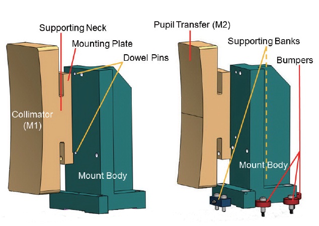
The mirror has a narrow neck and a mounting plate at the rear side to reduce the transfer of the excessive bolting stress to the mirror surface (Fig. 3). A similar type of stress-spreading mirror mount scheme has been used in a few previous instruments for circular off-axis mirrors (Rayner et al. 2003, Mok et al. 2006, Moon et al. 2006, Yoder 2008). We have extended the idea for rectangular sections of the off-axis parabola and ellipsoids, and optimized the relative dimension of the supporting neck and plate with the help of the FEA numerical structure analysis described in the next section. We have tested various combinations of the size of the neck and the plate to achieve the best-balanced choice between the mirror mass and the gravitational flexure.
Two dowel pins are applied for the precision assembly between the mounting plate and the mirror mount. One of the pin holes in the mirror is slightly slotted toward the other hole to mitigate a possible coefficient of thermal expansion mismatch during the cooling and warming of the system. The bottom of the mount has 1mm-raised pads to minimize the over-constraint issue on the contact of the mount and the optical bench surface. We have confirmed the fabrication feasibility of the shape and specification of the mirror by consulting at least two leading vendors in this market, including Axsys Technologies (USA) and Kaleido Technology (DK).
In this subsection, we describe the other two off-axis
collimators used for pupil transfer to the white pupil spots of the H and K channels and the position adjustment strategy for these using the alignment “bumpers.”
2.2.1 Off-Axis Ellipsoidal Mirrors for H and K Recollimators
The collimated beam produced by the primary collimating mirror is designed to be dispersed inside the silicon immersion grating, turning back through the grating incident surface, and reflected once again at the off-axis parabolic mirror. The dispersed and secondarily-reflected multicolor beams are to be converged into the polychromatic foci near the immersion grating. The convergent beams are now diverging to the second collimating surface called the pupil transfer mirror in each of the H and K bands (Figs. 1 and 3). These pupil transfer (M2) mirrors collimate the multi-wavelength rays again onto the cross-disperser VPH gratings, forming a superposed single pupil which we call white pupil (Schroeder 2000). Their surface figures are both off-axis ellipsoids, and are almost identical in H and K bands except for a tiny difference in their conic constants. The same procedure and reasoning logic are applied for the model optimization as for the primary collimator (M1). The pupil transfer mirrors have similarly shaped extended necks and supporting plates as the M1 collimator. However, they have a narrower mirror width than the previous one, resulting in a dimension of 130 × 35 mm2, based on the CA and the space economy.
2.2.2 Precision Adjustment Bumpers
The IGRINS optical design has chosen the pupil transfer mirrors as an alignment compensator in each spectrograph arm (Fig. 1). A conventional fine alignment procedure is
typically performed using micrometer sets installed around the target device by driving them with a manual feedthrough or in a motorized way (Thornton 2002, Thornton et al. 2003). However, since the IGRINS optics design is very compact and these mirrors are operated in a cryogenic environment, it is not appropriate to install additional micrometers around the mirror mounts.
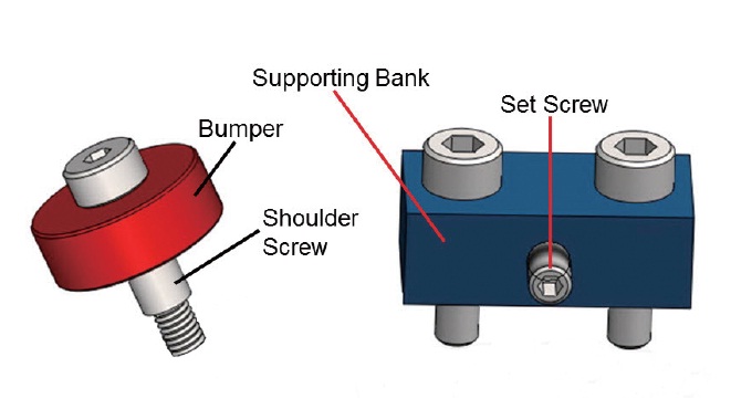
Dimension-controlled bumpers can be utilized for precision alignment of the cryogenic mirror mount in a crowded area by adjusting the radius of the ring and replacing it with different dimensional bumpers (Wilson 2010, Wilson et al. 2010). Three sets of bumpers are applied for each pupil transfer mount to execute translation motion and rotation, one at the back and two at a side (Fig. 3). Each bumper set consists of a shoulder screw and a precisely-machined aluminum ring (Fig. 4). The extruded smooth part of the shoulder screw under the bumper ring acts as a locating pin on the optical bench to secure the precise position.
The supporting bank at the opposite side of the bumper helps in relocating the mount in precisely the desired position when replacing the bumpers. The bank is a simple rectangular block providing a tapped hole at the center for a set screw. A moderately soft and solid tip of the set screw (e.g. Delrin tip) will supply regulated pressure from the other side of the bumper contact to improve the repeatability of the alignment task.
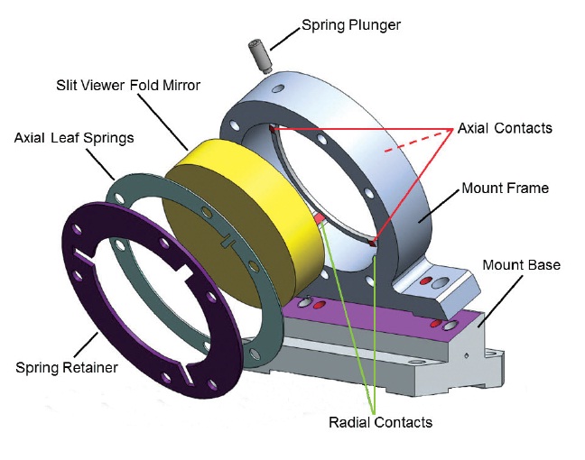
The slit-viewer fold mirror bends and relays the reflected light from the slit mirror tilted 22.5° relative to the normal to the optical bench into the slit-viewing camera (Fig. 1). The combination of the tilted angle of the slit mirror and the orientation of the slit-viewing camera detector requires the slit-viewer fold mirror to be leaned precisely 30° from the normal. For this reason, we separate the mirror mount into two parts: a mount frame with right-angled faces and a mount base with a 30°-slanted surface (Fig. 5). In a generic fabrication process, dimensional tolerance control on an arbitrarily angled part demands more effort and cost than a right-angled component. By dividing it into two parts, we may confine our attention to the sloped surface of the mount base when executing the acceptance test for the machined parts. Thorough and efficient performance of part-acceptance examinations takes priority over all else in IGRINS systems alignment strategy (Yuk et al. 2012).
An appropriate variation from the typical six-point kinematic optomechanical mount scheme is applied to this slit-viewer fold mirror mount (Moore et al. 2009). The mount frame is maintaining the circular flat Zerodur mirror with three equally spaced hard contact points in the axial direction and with two hard tangentially supporting points in the radial direction. The third radial support is provided by a spring plunger at the top center of the mount frame (McLean et al. 2008, Stahlberger 2010). The three axial hard points will be used as positional references for assembly and alignment. The radial reference points do not require high precision, as this folder is a flat mirror with spare clearance. From the back side of the mirror, three leaf springs are pressing the mirror at the opposite points of the axial contact areas on the front surface (Fig. 5). The three tiny springs are attached together in a single rim for convenience of handling and maintenance.
The leaf springs are made of titanium Ti-6Al-4V alloy to improve the resultant factor of safety (FOS) of the thin-narrow metal bar owing to its larger yield strength than other common materials such as steel or brass (Stahlberger 2010). The first order estimate of the maximum deflection and the spring dimension can be obtained with the theoretical formula (Avallone et al. 2007),
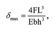
where F is the applied force, E is the elastic modulus of Ti-6Al-4V, L is the length, b is the width, and h is the thickness of a rectangular bar. Through the detailed numerical FEA analysis described in Section 3, we have determined the spring length, width, and thickness as 6 mm, 1.4 mm, and 0.35 mm, respectively. With this parameter set, each leaf spring will exert 1 N or 3 G supporting force on the mirror back while being deflected by 0.2 mm away from the mirror. The neck of a spring is the mechanically weakest point in the whole mirror mount assembly, although its FOS is higher than 3. Therefore, we designed an additional retainer ring so that it can work as a backup safety structure
in case an unexpected over-ranged external acceleration or deceleration is applied to the mirror (Fig. 5). The Delrin-tipped spring plunger at the top of the mount frame is designed to work with the spring constant of 1 N/mm, corresponding to 3 G force for 1mm screw insert.
3. STRUCTURE ANALYSIS AND STABILITY TOLERANCE
The tolerances of an optical instrument can be divided into two groups, static tolerances and dynamic tolerances. The static tolerances can also be called pre-assembly tolerances with no movement involved, and the dynamic tolerances be called post-assembly tolerances involving the instrument movement in its operation. The IGRINS optical tolerance report includes four categories of tolerances: fabrication, alignment, component stability, and alignment stability (Jaffe 2011). The first two are static requirements for which one should make proper fabrication and alignment plans with quality control accordingly, and the second two are to be treated as dynamic requirements that we should meet during the instrument operation phase.
The optics fabrication tolerance does not cause any direct issues in the mechanical mount design. The IGRINS alignment tolerances on the mirrors under consideration in this paper read as ±100 μm for both decenter and separation, and as ±3′ for tip-tilt. The alignment tolerances sometimes may create practically challenging requirements for the optics mount scheme. However, this grade of alignment tolerances is fairly generous, and thus we can readily satisfy the requirements by adopting the precision machined locating pin approach. Therefore in this section we only describe the stability tolerances for alignment and optical components that are to be complied with according to the series of FEA analyses. SolidWorks® Simulation Pro 2011 has been used throughout this work.
One of the typical dynamic instabilities is raised by the resonance frequencies of a mechanical support structure. However, the mirror mounts designed in this study come
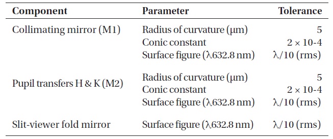
[Table 1.] Physical specification of the four mirrors.
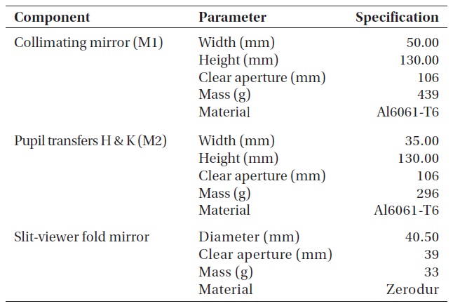
Physical specification of the four mirrors.
out with almost 1,000 Hz 1st mode natural frequencies, which is far beyond our concerns. The primary source of optomechanical instability in the IGRINS system is the gravitational deformation of an optical component and its mechanical mount. Thus, in this subsection, we present the results of the gravitational flexure analyses before comparing these with the stability tolerances of the optical system. The SolidWorks® Static Simulation calculates the distribution of stress, displacement, strain, and FOS etc. However, the structural safety has never been an issue in the mirrors and their mounts of IGRINS except for the leaf springs (Fig. 5), so the investigation into the displacement alone would be enough for those mirror mount designs.
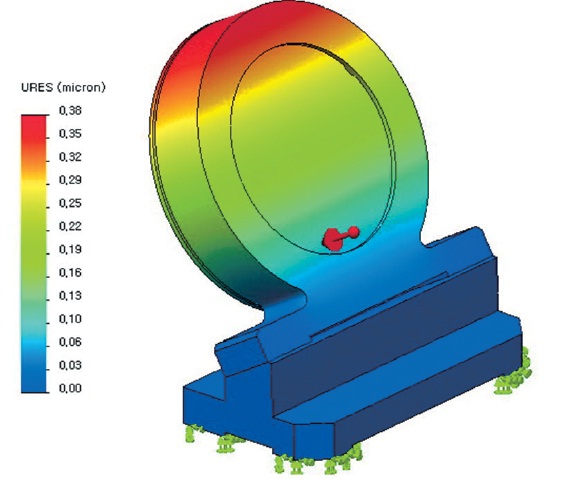
Fig. 6 shows the distribution of the FEA resultant displacement of the collimating mirror (M1) due to 1 G external gravity force applied to the normal direction of the mirror surface. The maximum 0.30 μm geometric distortion occurs at the top-side end of the CA and the minimum 0.10 μm deflection at the bottom-side end (Fig. 2), which corresponds to the 0.46″ tilt of the mirror. For the H and K-band pupil transfer mirrors (M2), the FEA simulation shows similar displacement behavior, but with 20% less deformation than the M1 simulation. This is because the M2 mirrors have a lighter weight than the primary collimator (Table 1). Any other orientation of gravity does produce less mirror surface displacement than the gravity direction chosen in Fig. 6.
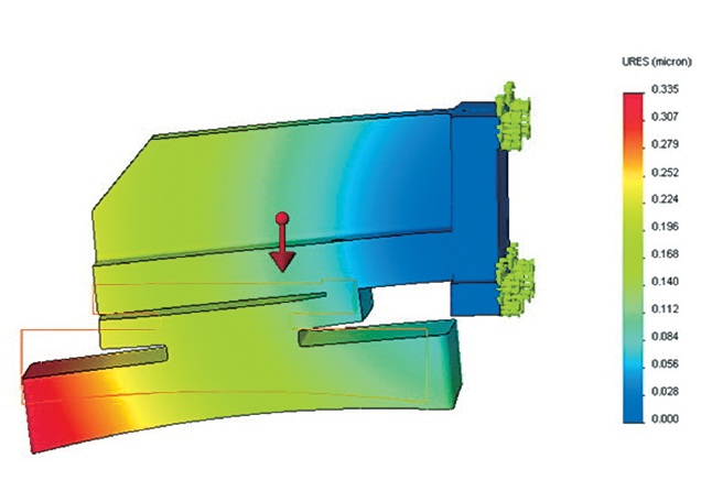
Fig. 7 is a simulation case of maximum gravity effect on the slit-viewer fold mirror installed on its mount, where the gravitational force is pointing in the normal direction of the mirror surface. Although the mirror material, shape, and the mount scheme are entirely different, the displacement pattern and quantities in the Zerodur fold mirror are very close to that of the aluminum collimator, i.e., maximum 0.30 μm and minimum 0.10 μm in the CA area, corresponding
[Table 2.] Alignment stability tolerances of the four mirrors (Jaffe 2011).

Alignment stability tolerances of the four mirrors (Jaffe 2011).
to 1.5″ tilt of the mirror. In the SolidWorks® Simulation, the resultant details depend on the mesh size of the finite element method, even with identical external conditions. For this reason, we tested various scales of mesh until reaching a convergent solution within 10% of the maximum deflection. Interpretations of these FEA results are given in the next two subsections by comparing with the alignment stabilities and the optics component stabilities.
3.2 Alignment Stability Tolerances
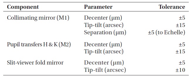
IGRINS will be mounted on and used at the straight Cassegrain port of the McDonald 2.7 m HJST (Lee 2010). The instrument is supposed to be moving along with the telescope while observing, which will inevitably cause the optomechanical mounting structures to be flexed by the variable gravity orientation. The optical design requires the gravitational deflection to be smaller than the alignment stability tolerances during at least one-hour exposure or 15° altitude change. The IGRINS critical design review report (Jaffe 2011) says that the M1 collimator alignment should be stable within ±5 μm decenter, ±15″ tip-tilt, ±5 μm separation to the immersion grating, and the slit-viewer fold mirror should stay within ±5 μm decenter, ±10″ tip-tilt. The H and K pupil transfers have the same degree of alignment
stability tolerances except for the separation, since those M2 recollimators are used as alignment compensators.
Table 2 lists the alignment stability tolerances for all mirrors considered in this study.
Since the three collimators and the slit-viewer fold mirror have a range to be deflected by 0.30μm at most (Fig. 6), the mirror decenters or separations induced by the gravitational disturbance can never reach their alignment tolerances ±5 μm. In addition, their angular instabilities due to the gravity (0.46″ for the collimators and 1.5″ for the fold mirror) are also far less than the tip-tilt alignment stability tolerances of the mirrors (±15″ for the collimators and ±10″ for the fold mirror). Therefore, the mirror mount designs for the collimators and the slit-viewer fold mirror satisfy the alignment stability requirements.
3.3 Optical Component Stability Tolerances
The gravitational FEA sag (δFEA) presented in the previous section can be broken down into two key pieces of information: (1) the systematic radius of curvature (RC) variation and (2) the surface figure irregularity. The systematic RC variation includes the rigid body surface movement in decenter, tip-tilt, and defocus (δrc). The surface figure irregularity is the measure of offset from the fiducial surface shape, commonly represented by the peak-to-valley (δp-v) or root-mean-square (δrms). For a successful optomechanical system, both components of the sag must be within the optical surface stability tolerances, which are summarized in Table 3 3 for the mirrors under consideration. Of all IGRINS optics tolerances, these component stability tolerances are the tightest. The stability requirements say that it should be less than 5 μm for the collimators RC variation and smaller than 63 nm (rms) for all mirror surface instabilities. Instead of making a
[Table 3.] Optical component stability tolerances of the four mirrors (Jaffe 2011).

Optical component stability tolerances of the four mirrors (Jaffe 2011).
straightforward comparison of those numbers, we put an interpretation on the two matching-counterpart items in order to make it palpable for somewhat intangible issues.
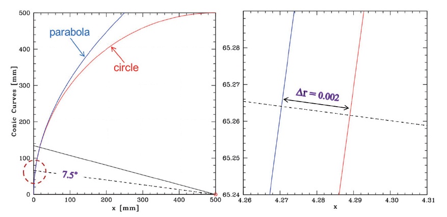
First, what can we directly compare with the non-spherical RC stability tolerances? A conic optical surface can be treated as a spherical surface with the same RC when the paraxial approximation is valid (Smith 2008). Fig. 8 shows how parabolic and circular conic curves are close together near the optical axis. The radial difference △r between the two curves at the 7.5° off-axis edge of the IGRINS collimating mirror is less than 2 μm, which is a fraction of 4 × 10⁻⁶ relative to the RC 500 mm. Thus, the collimator parabolic surface may be taken as a spherical surface with the same RC, if a 0.0004% RC mismatch is accepted. For a spherical surface, the maximum gravitational sag (δFEA) on the mirror CA top can cause the maximum radius variation to be R ± δFEA. Although the systematic RC change practically dominates the surface irregularity, the total gravitational flexure is always greater than the RC variation alone, since it is the superposition of the two components: δFEA = δrc + δrms. Therefore, we may conclude that for a paraxial application, an RC stability requirement of an aspherical conic surface will be met when the maximum gravitational sag is smaller than the RC stability tolerance of the surface. This also supports the premise that the IGRINS Collimator and Pupil Transfer mirrors gravitational flexures (0.30 μm) satisfy the optical surface RC stability tolerances (5 μm).
Second, how can we estimate the surface figure irregularity component from the gravitational sag analysis? From the displacement scan of Fig. 6 and Fig. 7 across the mirrors from the bottom to the top, one can notice that the deflection quantities are increasing in an almost linear manner along the scanned line on the mirror surfaces. Both mirrors have the same amount of FEA sag value, 0.20 μm, at the center of the CAs. We will take this average flexure as the component of the systematic RC change due to the gravity. Then, the residual offset distribution above or below the fiducial mirror surface will be the component of surface figure irregularity. Assuming the sinusoidal error patterns, both mirrors have δp-v of 0.20 μm. If we take 1/3 of the δp-v for δrms, it leaves 66 nanometers of surface irregularity rms. This is equivalent to or slightly higher than the stability requirement. However, if we consider the required one-hour single exposure observation or 15° telescope altitude change (Lee 2010), the practical δrms comes to be reduced down to a quarter of the maximum δrms (or 66 nm), resulting in 16nm surface figure irregularity rms for both types of mirrors under consideration in this paper.
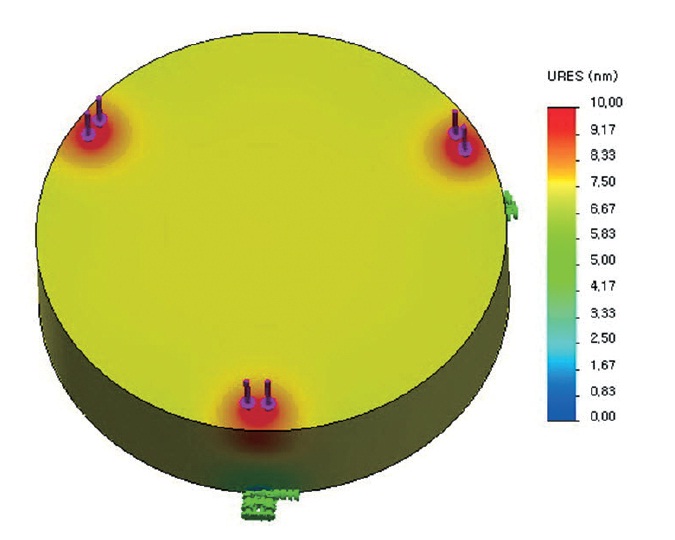
The other surface figure perturbation source to be considered on the slit-viewer fold mirror is the contacting stress due to the spring pressure. Fig. 9 shows the resultant displacement distribution on the fold mirror. The three axial contact points on the mount frame are used as fixed geometry, and the three spring contact points are simulated as external force applied spots (see the model at Fig. 5). A systematic surface movement of about 7 nm has occurred throughout the mirror. A linear scan across the mirror surface along an arbitrary orientation proves the surface figure irregularity to be less than 2 nm rms, which is far below the requirement of λ/10.
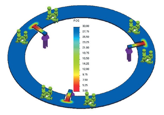
The IGRINS systems engineering team has fixed the lower limit of the FOS to be more than 3 throughout the instrument mechanical and optomechanical structures (Lee 2010). The mirror mount designs developed in this study
include only a single part that demands good care of its FOS, which is the set of leaf springs (Fig. 5). Fig. 10 displays the FEA result for the FOS of the titanium rim putting the leaf springs together for the slit-viewer fold mirror kinematic mount. Although the spring neck areas turned out to be the weakest mechanical points, the FOS has been successfully arranged to be higher than 3 all around the part. The individual force applied with a spring needs to be cautiously balanced between the mirror weight-supporting stiffness and the mirror surface-protecting flexibility. We have determined to apply a total of 3 N or 9 G spring force to the mirror from the rear side.
4. THERMAL ANALYSIS OF THE MIRRORS
In this section, we investigate the static temperature distribution and transient temperature behavior of the optical components using the FEA thermal calculation method. First, the simplified simulation model and the boundary conditions are described, and then the calculated results and our interpretations are presented.
4.1 Thermal Model and Boundary Conditions
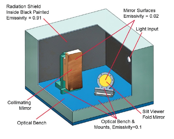
The simplified thermal model involved in this study consists of an optical bench, a five-sided radiation shield, a collimator mirror and mount assembly, and a slit-viewer fold mirror and mount assembly (Fig. 11). We ignore the temperature gradient effect across the optical bench and
radiation shield, conduction through the Delrin tip of the spring plunger, scattered radiation through entrance window, existence of neighbor components, and so on. It is estimated that the collective contribution of those neglected items will be less than 5% of the total system thermal budget. Throughout this analysis, any contact point or surface between parts is assumed to be thermally perfect, with no resistance.
Boundary Conditions adopted in this FEA study are as follows: materials for all parts are Al6061-T6, except for the Zerodur slit-viewer fold mirror. Cryogenic temperature dependent properties of aluminum-specific heat have been updated in the SolidWorks® Simulation parameter setting. The optical bench and radiation shield provide the environmental temperatures into the individual optics with the final equilibrium of 125 K and 130 K, respectively. Temperature temporal variations of optical bench and radiation shield are given by previous studies on the IGRINS cryostat (Jaffe 2011, Oh et al. 2011). Radiative heat exchanges between interior surfaces of radiation shield (black painted, emissivity 0.91), mirror mounts and optical bench interior surfaces (bare aluminum, emissivity 0.10), and both mirror surfaces (protective gold coating, emissivity 0.02) are included in the calculation (Fig. 11).
4.2 Thermal Behavior of the Mirrors
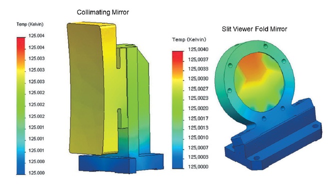
We performed static and transient analyses to examine the equilibrium temperature distribution across each mirror surface and the cooldown behavior while reaching the goal temperature. The required steady state temperature for the optical components is any stable value between 120 K and 130 K with the stability of 1 K rms (root mean square). Another requirement is to achieve a temperature gradient smoother than 4° per 100 mm local separation across the optical bench in order to maintain the uncertainty caused by differential thermal contraction as less than a typical 10 μm fabrication precision (Lee 2010). Fig. 12 shows the steady state temperature distribution across the mirrors and mounts. It has an almost identical temperature throughout the mirrors, showing an end-to-end difference of only a few milli-Kelvin. Therefore, the IGRINS mirror mount designs developed in this study will be thermally stable enough to meet all the system temperature requirements.
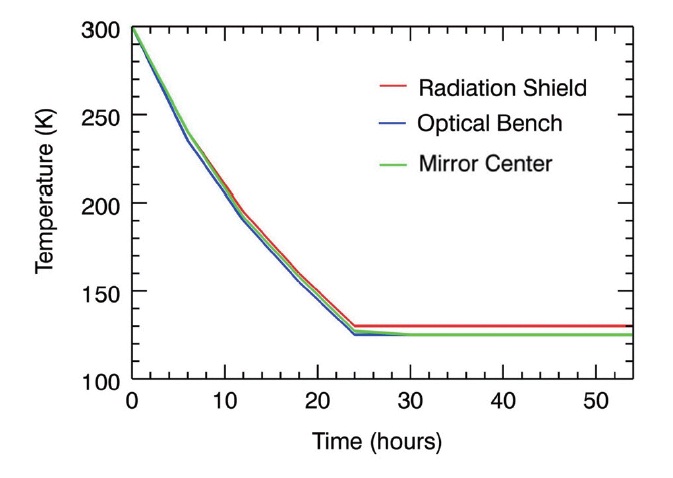
The transient thermal study is shown in Fig. 13. From this plot we can inspect the cooldown behavior of the optical parts and determine the components’ cooling time to see if
any design modification is needed to meet the cooldown-time requirement. The red line represents the radiation shield, the blue line the optical bench, and the green line a mirror center. There is virtually no difference between the collimator and the slit-viewer fold mirror, although their material and mounting scheme are far from similar. The temperature of the optical components follows the optical bench behavior in real time, practically speaking. Therefore, we may conclude that the four mirrors studied in this paper show the same thermal behaviors as the optical bench upon which they are installed.
The unique broad-band high-resolution high-throughput state-of-the-art immersion-grating astronomical spectrograph IGRINS is working with a total of nine reflective optical elements, including three aspherical off-axis mirrors, four flat fold mirrors, and a dichroic mirror and a slit mirror. Of these, the three off-axis collimating mirrors and one slit-viewer fold mirror are considered in this optomechanical design study.
Narrow accessible space, high precision alignment, tight stability tolerances etc. are threatening factors in this design work. With remaining minimal margin beyond CAs, we have left as small a section of the optics as we can in order to butt into crowded available optomechanical real estate in the field of optical bench. Instead of taking a conventional micrometer feedthrough approach for repeated alignment of the system compensators, we use a set of dimension-controlled precision bumpers to straightforwardly address both the space issue and the alignment requirements. By dividing the slit-viewer fold mirror mount into two parts, one right-angled mount frame plus a mount base with a single 30°-slanted surface, we can reduce fabrication costs and perform the parts acceptance test more comprehensibly and efficiently.
We have performed gravitational FEA flexure simulation, resulting in maximum mirror deflection from the fiducial surface up to 0.30 μm for both of the off-axis collimator and the slit-viewer fold mirror, which correspond to 0.46″ and 1.5″ tilt, respectively. The maximum FEA gravitational sag values are compared with the counterparts of stability tolerances, verifying that our mirror mount designs satisfy all known IGRINS optical stability requirements. A set of leaf springs of the slit-viewer fold mirror mount is the only part that raises FOS related questions in this work. For the current spring model, we have adjusted the spring dimensional specification so that its structural FOS can be larger than 3 through the entire part.
A static thermal analysis shows that the mirror mount designs all satisfy the operational temperature requirements. In addition, the transient thermal study supports the conclusion that the mirrors and their mount assemblies are thermally well coupled with the optical bench to follow the thermal behavior of the cold plate with no significant time-lag.