Kinematic global positioning system precise point positioning (GPS PPP) technology is widely used to the several area such as monitoring of crustal movement and precise orbit determination (POD) using the dual-frequency GPS observations. In this study we developed a kinematic PPP technology and applied 3-pass (forward/backward/forward) filter for the stabilization of the initial state of the parameters to be estimated. For verification of results, we obtained GPS data sets from six international GPS reference stations (ALGO, AMC2, BJFS, GRAZ, IENG and TSKB) and processed in daily basis by using the developed software. As a result, the mean position errors by kinematic PPP showed 0.51 cm in the east-west direction, 0.31 cm in the north-south direction and 1.02 cm in the up-down direction. The root mean square values produced from them were 1.59 cm for the east-west component, 1.26 cm for the south-west component and 2.95 cm for the up-down component.
The precise point positioning (PPP) method was developed by the US Jet Propulsion Laboratory (JPL) in the late 1990's. In this method, the position of the receiver is independently calculated with high accuracy without referring to a specific reference station for correctional information (Zumberge et al. 1997). The PPP data processing method uses orbit/clock products of the navigation satellites for initial input, and the accuracy of the processed final products relies on the orbit or clock information of the satellites. The orbit error of a global positioning system (GPS) satellite currently provided by the international GNSS service (IGS) is less than about 2.5 cm, and the satellite clock error is about 75 pico-second (ps) in the root mean square (RMS) (http://igscb.jpl.nasa.gov/components/prods.html). As the accuracy and precision of the final products from the IGS analysis centers have improved, a highly precise positioning of a GPS reference station has become possible using the PPP method.
There are two types of PPP data processing methods depending on the application purposes; the static positioning and the kinematic positioning (Kouba & Heroux 2001). In the static positioning method, constraints are generally on the movement of the user’s position among the parameters to be estimated. In other words, noise by time in the state parameter of position is not considered as long as the estimating filter is sequential (Choi et al. 2011). The static positioning method is useful in processing such measurements received in a static state as that for a GPS reference station, and particularly effective in keeping position information reliable and in estimating tropospheric information. On the other hand, in the kinematic positioning method, data is processed under the assumption that the user is moving when the GPS signals are received. This method is very useful for car navigation systems, etc., and especially for precisely estimating courses of aircrafts and orbits of low-earth-orbit satellites (Choi et al. 2009). Detection of a minute movement of the crust by an earthquake is another application of the kinematic positioning method.
The PPP method needs initial convergence time to stabilize such parameters to estimate as float ambiguities; estimated state parameters are not accurate enough during the initial convergence. Thus, a solution to reduce the initial convergence time is desired, and one is to determine integer ambiguities by un-differenced GPS data (Laurichesse et al. 2009, Geng et al. 2010). It is not easy to determine the integer ambiguities, however, since the GPS data include un-calibrated hardware biases of the satellite and the receiver.
Hauschild & Montenbruck (2009) estimated initial state parameters using a forward / backward filter for their PPP estimation of the GPS satellite clock, and Salazar et al. (2009) obtained reliable results by employing a forward / backward filter in their post-processing of the GPS PPP data. In this study, we apply a 3-pass (forward/backward/forward) filter to an extended Kalman filter (EKF) in order to compensate the inaccuracy of the initial state parameters. The estimated parameters, including the positions of the IGS reference stations, are re-determined by applying the 3-pass filter to the data processing of kinematic PPP. Also, we compare our results with the final products provided by IGS to assess the performance of our data processing method.
GPS dual frequency data are necessary for a very precise estimation of user’s position, receiver clock error, tropospheric delay error, etc. The GPS dual frequency data are divided into code phases and carrier phases. A code phase is divided into P1 and P2 codes, while a carrier phase is classified into L1 (1,575.42 MHz) and L2 (1,227.60 MHz) frequencies.
A linear combination of the dual frequency data can eliminate more than 99% of the ionospheric error which is the greatest error in the transmission of GPS signal. Eqs. (1) and (2) are observation equations for the linear combination of the two code phases and carrier phases (Hofmann-Wellenhof et al. 2008):
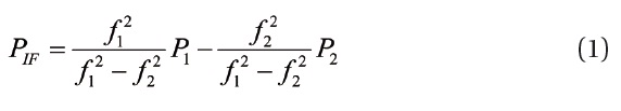
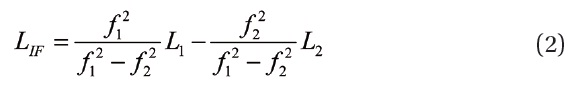
where
EKF is applied in order to estimate such state parameters as the user’s position by using the kinematic PPP. Eqs. (3) and (4) shows the update and prediction of the state parameters, respectively (Welch & Bishop 2002):
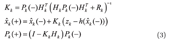
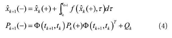
where

denotes the state parameter,
, consists of the variables of [
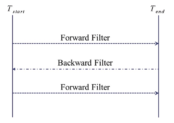
In the kinematic PPP, the initial convergence is necessary and the estimated parameters remain inaccurate until the stabilization is complete. To compensate this drawback, we apply the 3-pass filter (forward/backward/forward) to EKF:
-Forward filter
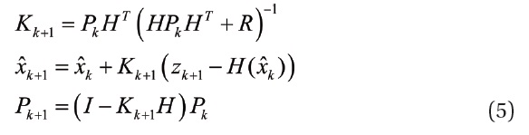
-Backward filter
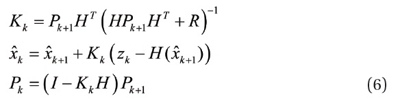
The 3-pass filter consists of a forward filter and a backward filter as in Eqs. (5) and (6). The forward filter is applied first to the entire range of the state parameter estimation, and then the backward filter is applied backward to the same range again to process the data (Fig. 1). And finally, the forward filter is applied once again to process the data and calculate the final parameters. It is important here to initialize only the
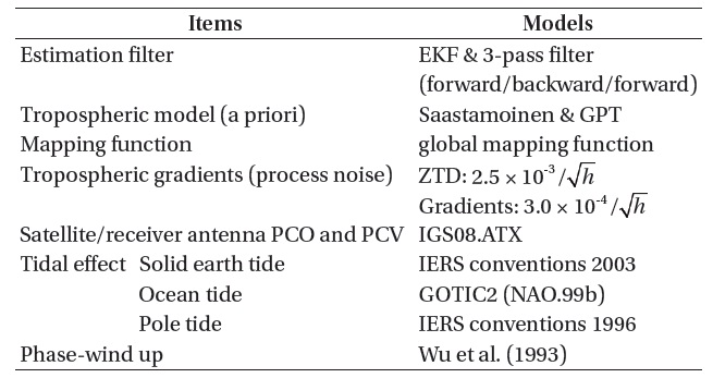
[Table 1.] Detailed models and settings for kinematic PPP.

Detailed models and settings for kinematic PPP.
without changing the state parameters at the points where the backward filter replaces the forward filter and vice versa.
To verify the performance of position accuracy by the kinematic PPP method developed in this study, we select 6 GPS sites of international GPS reference stations (ALGO, AMC2, BJFS, GRAZ, IENG, TSKB) and analyze the GPS data received for 5 days in total from March 3 to March 7, 2012.
Table 1 shows the models applied to the data processing of kinematic PPP. EKF and the 3-pass filter are employed as the data processing filters, and a priori for the tropospheric signal delay is calculated by the Saastamoinen model. For a mapping function for the conversion of the tropospheric delay error from the line-of-sight direction to the zenith direction, we use the global mapping function developed by Boehm et
al. (2006). Pressure and temperature information, which is required to input for the calculation of the tropospheric delay error, is obtained by using the global pressure and temperature model. Variations in the zenith total delay and the gradient through the troposphere are assumed as random walks for the estimation, and noises in the data processing for those two parameters are set to be 2.5 × 10⁻³ /

and 3.0 × 10⁻⁴ /
, respectively, where
The phase center offset and the phase center variation of the GPS satellite antenna and the receiver are calculated based on the antenna information file, IGS08.ATX, provided by IGS.
The models suggested at the International Earth Rotation Service (IERS) Conventions 2003 and the IERS Conventions 1996 are applied for the influences by the earth and pole tides, and the GOTIC2 (NAO.99b) model is used for the ocean tide.
3.2 Verification of the Position Accuracy
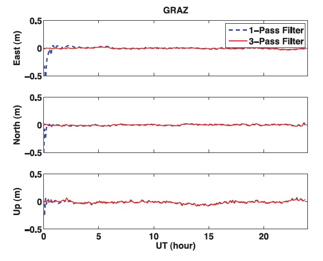
Fig. 2 presents the result from applying the kinematic PPP method to the dual frequency data received by the GRAZ GPS reference station in Germany on March 3, 2012. This result shows the difference in the position accuracies estimated by a 1-pass filter (forward) and the 3-pass filter. With the 1-pass filter, the position accuracy stays low during the initial convergence as represented by the dotted line in Fig. 2, while the 3-pass filter results in more reliable position information as shown by the solid line.
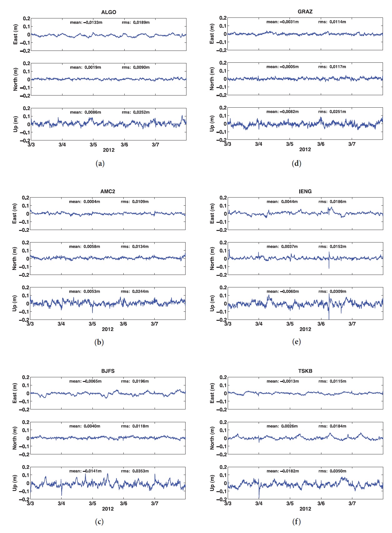
Figs. 3a-f show errors in the positions of the GPS reference stations obtained by processing the GPS observables received at the stations of ALGO, AMC2, BJFS, GRAZ, IENG, and TSKB, respectively. The data were received at
each station for 5 days from March 3 to March 7, 2012, and are processed on a daily basis. The position information of a reference station is calculated for every 30 seconds, and compared for verification with the IGS08 coordinates provided by the IGS analysis center. IGS adopted ITRF2008 (International Terrestrial Reference Frame), released in May 2010, as a new reference frame. The IGS08 coordinate system is a realization of ITRF2008 (Altamimi et al. 2011).
Results from the data at ALGO GPS site are presented in Fig. 3a. The mean position error for the station, processed over 5 days in total, is approximately -1.33 cm in the east-west direction, 0.19 cm in the north-south direction, and 0.86 cm in the vertical direction. The RMS of the position error is approximately 1.89 cm in the east-west direction, 0.9 cm in the north-south direction, and 2.52 cm in the vertical direction. These results show that, for the position error of the ALGO station, the component of north-south direction is most reliable and the greatest value is the vertical component of the effective value. Fig. 3b is for the processed results from the AMC2 reference station. The mean position error for the AMC2 reference station is less than 1 cm for all the components of east-west, north-south, and vertical directions. The effective value of the position error is approximately 1.09 cm in the east-west direction, 1.34 cm in the north-south direction, and 2.44 cm in the vertical direction. For the AMC2 reference station, the east-west components of the results are more reliable than the north-south components. Fig. 3c shows the results from the BJFS reference station, where the mean value of the position error is approximately 0.65 cm in the east-west direction, 0.40 cm in the north-south direction, and -1.14 cm in the vertical direction. The RMS values of the position error are approximately 1.96 cm, 1.18 cm, and 3.53 cm in the east-west, north-south, and vertical directions, respectively. In the case of the BJFS results, the RMS values of the position error in the vertical direction are relatively larger than those for other reference stations. Fig. 3d is for the GRAZ reference station. In this case, the absolute mean value of the position error is less than 1 cm for all the directional components, and the RMS values are 1.16 cm, 1.18 cm, and 2.55 cm for the east-west, north-south, and vertical components, respectively. The mean position error for the GRAZ station is similarly reliable with that for the AMC2 station. Results from data processing for the IENG station are presented in Fig. 3e. The absolute mean value of the position error for the IENG station is less than 1 cm for all the components as in the cases of the GRAZ and AMC2 stations, and the RMS value for the north-south component is reliable with 1.15 cm, while the RMS value for the east-west component is a little bit large with 2.31 cm. Finally, Fig.3f
[Table 2.] The mean position errors and RMS values.
The mean position errors and RMS values.
shows the results from the TSKB station, where the mean position error is -0.13 cm, 0.26 cm, and -1.82 cm in the east-west, north-south, and vertical directions, respectively. The east-west and north-south components of the mean error are calculated to be small, but the vertical component has the largest error. In the case of the TSKB station, the mean position error in the north-south direction is accurately calculated to be 0.26 cm, while the RMS value in the same direction is large to be 1.84 cm. As seen in Fig. 3f, the north-south component of the position error repeats a similar pattern every day, which is considered to be caused by a multipath error of the GPS signal coming from a specific direction.
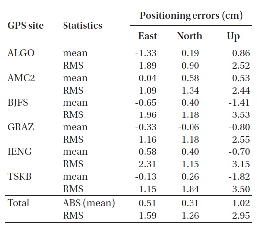
Table 2 summarizes the mean and RMS values of the position errors for each directional component resulting from the data processing with the kinematic PPP method for the 6 GPS reference stations. Summing up the results from each station, the mean position error is approximately 0.51 cm, 0.31 cm, and 1.02 cm for each component. As presented in the table, the kinematic PPP method obtains very accurate values of the mean position error with less than 1 cm for all the horizontal components of direction (east-west and north-south). The RMS values of the position error are approximately 1.59 cm, 1.26 cm, and 2.95 cm for three components, and it is noted that the north-south component of the RMS value is more reliable than the vertical component.
In this study, we developed the kinematic PPP method, where a 3-pass (forward/backward/forward) filter is applied to the data processing in order to compensate the inaccuracy of the state parameters during the initial stage of convergence. As a result, position information is reliably obtained through the entire range of data processing. We processed the GPS data received for 5 days in total from March 3 to 7, 2012 at six reference stations (ALGO, AMC2, BJFS, GRAZ, IENG, TSKB) which are serving as international GPS reference points. For verification, we compared the estimated position for each GPS reference station with the IGS08 coordinates provided by the international analysis centers. Summing up the processed results, the mean position error is 0.51 cm in the east-west direction, 0.31 cm in the north-south direction, and 1.02 cm in the vertical direction. The RMS values of the position error are 1.59 cm in the east-west direction, 1.26 cm in the north-south direction, and 2.95 cm in the vertical direction. In conclusion, we demonstrated that the kinematic PPP method of data processing, developed in this study, can produce a very precise and reliable result.